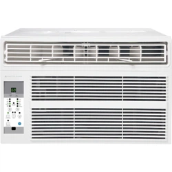
WINDOW AIR CONDITIONER
M
ODELS 2AWH18000A, 2AWH24000A
OWNER’S MANUAL

IMPORTANT:
Thank you for your purchase. Please read this manual carefully before operating.
Make sure to save this manual for future reference.
ARCTIC W IN D

IMPORTANT SAFETY INSTRUCTIONS ...............................................3
ELECTRICAL REQUIREMENTS .....................................................4
PACKING LIST ...................................................................5
INSTALLATION & ASSEMBLY INSTRUCTIONS .........................................6
THROUGH-THE-WALL INSTALLATION INSTRUCTIONS .................................12
USING YOUR AIR CONDITIONER ..................................................13
OPERATING YOUR AIR CONDITIONER ..............................................15
CARE AND CLEANING ...........................................................16
TROUBLESHOOTING ............................................................17
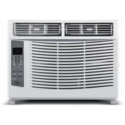
TABLE OF CONTENTS
FOR WINDOW AIR CONDITIONER MODEL
2AWH8000A
2AWH12000A
ARCTIC W IN D
IMPORTANT SAFETY INSTRUCTIONS
3
Before installing and using your air conditioner, please read this owner’s manual carefully. Store this
manual in a safe place for future reference. Your safety and the safety of others is very important to
us. Please pay attention to all safety messages outlined in this owner’s manual.
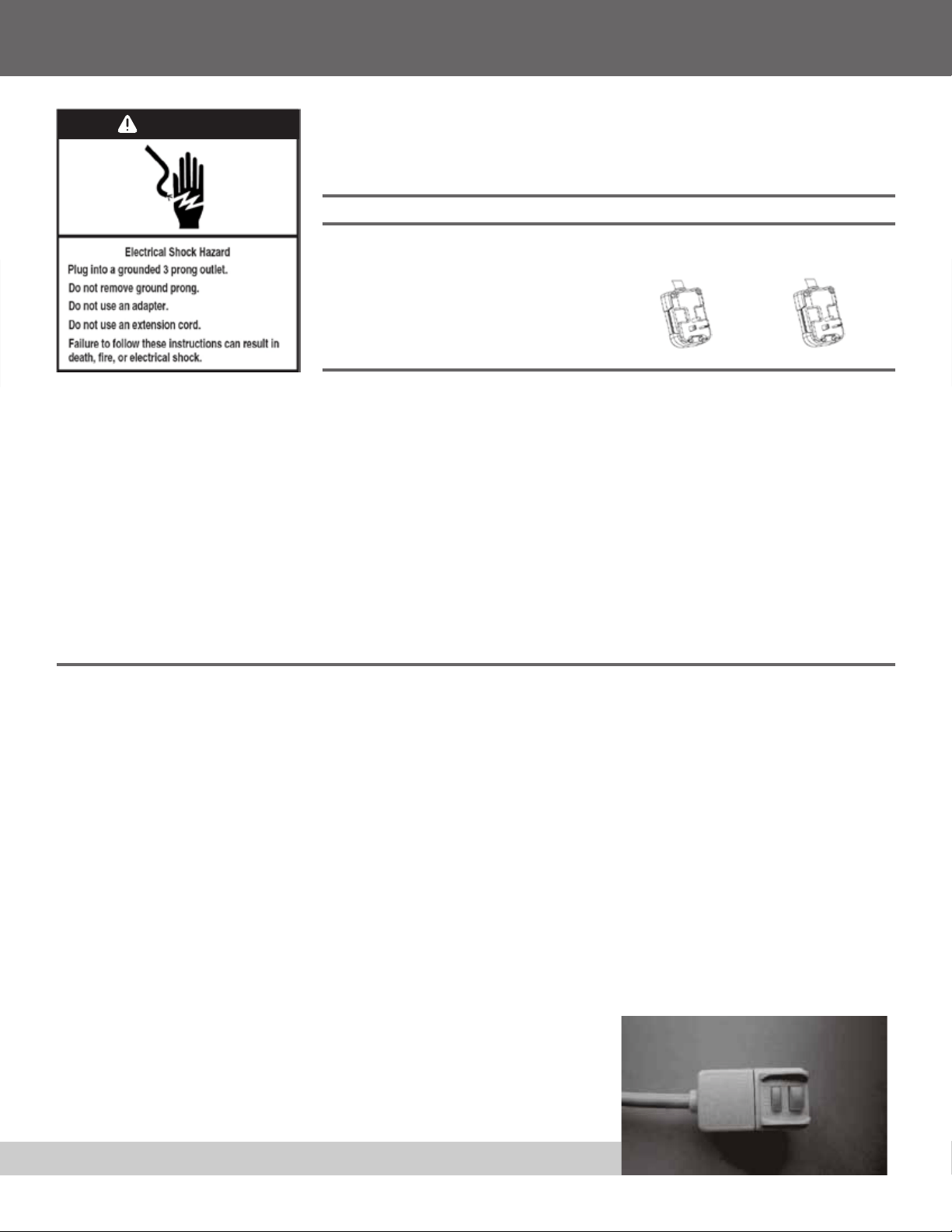
WARNING: To reduce the risk of fire, electrical shock, or injury when using your air conditioner, follow
the following basic precautions:
• Plug into a grounded 3 prong outlet
• Do not remove the ground prong
• Do not use a plug adapter
• Do not use an extension cord
• Unplug the air conditioner before servicing
• Use two or more people to move and install
the air conditioner
This is a safety alert symbol.
This symbol alerts you to potential hazards that can harm you or others or
even cause death.
All safety messages will directly follow the safety alert symbol and/or the
words
“DANGER” or “WARNING”.
Failure to immediately follow
these instructions may cause
serious injury or even death.
All Safety messages alert you of potential hazards, how to reduce the chance
of injury, and what can happen if instructions are not followed correctly.
WARNING
DANGER
ELECTRICAL REQUIREMENTS
4
The electrical ratings for your air conditioner are listed on the model and serial
number label located on the front left side of the unit (when facing the front).
Specic electrical requirements are listed in the chart below. Follow the
requirements below for the type of plug on the power supply cord.
• 230
volt (103min.–127max)
• (18K heating) 20A time-delay fuse
or circuit breaker
• (24K heating) 20A time-delay fuse
or circuit breaker
• Use on single outlet circuit only
Wiring Requirements Power Supply Cord
18
K Heating
24
K Heating
Recommended Ground Method
For your personal safety, this air conditioner must be grounded. This air conditioner is equipped with a 3
prong power supply cord with a grounded plug. To minimize the possibility of electrical shock, the cord must
be plugged into a 3 prong outlet and grounded in accordance with all local codes and ordinances. If a 3 prong
outlet is not available, it is the customer’s responsibility to have a properly grounded 3 prong outlet installed
by a qualied electrician.
LCDI Power Cord and Plug
This air conditioner is equipped with an LCDI (Leakage Current Detection and Interruption) power cord that is
required by UL. This power supply cord contains state-of-the-art electronics that sense leakage current. If the
cord is damaged and leakage occurs, power will be disconnected from the unit.
The test and reset buttons on the LCDI Plug are used to check if the plug is functioning properly.
To test the plug:
1. Plug power cord into a grounded 3 prong outlet
2. Press RESET (on some units a green light will turn on).
3. Press the TEST Button, the circuit should trip and cut all power to the air conditioner (on some units a
green light may turn o.
4. Press the RESET button for use. You will hear a click and the A/C is not ready for use.
NOTES:
• The RESET button must be engaged for proper use.
• The power supply cord must be replaced if it fails to trip when the TEST button is pressed and the unit fails
to reset.
• Do not use the power supply cord as an ON/OFF switch. The power
supply cord is designed as a protection device.
• A damaged power supply cord must be replaced with a new power
supply cord.
• The power supply cord contains new user serviceable parts. Opening
the tamper-resistant case voids all warranty and performance claims.
NOTE: Your units power cord and plug may differ from the one shown.
It is the customer’s responsibility:
• To contact a qualied electrician
• To assure that the electrical installation is adequate
and in conformance with the National Electrical
Code, ANSI/NFPA 70 - latest edition, and all local
codes and ordinances.
Copies of the standards listed may be obtained from:
National Fire Protection Association
One Batterymarch Park
Quincy, Massachusetts 02269
WARNING
PACKING LIST
5
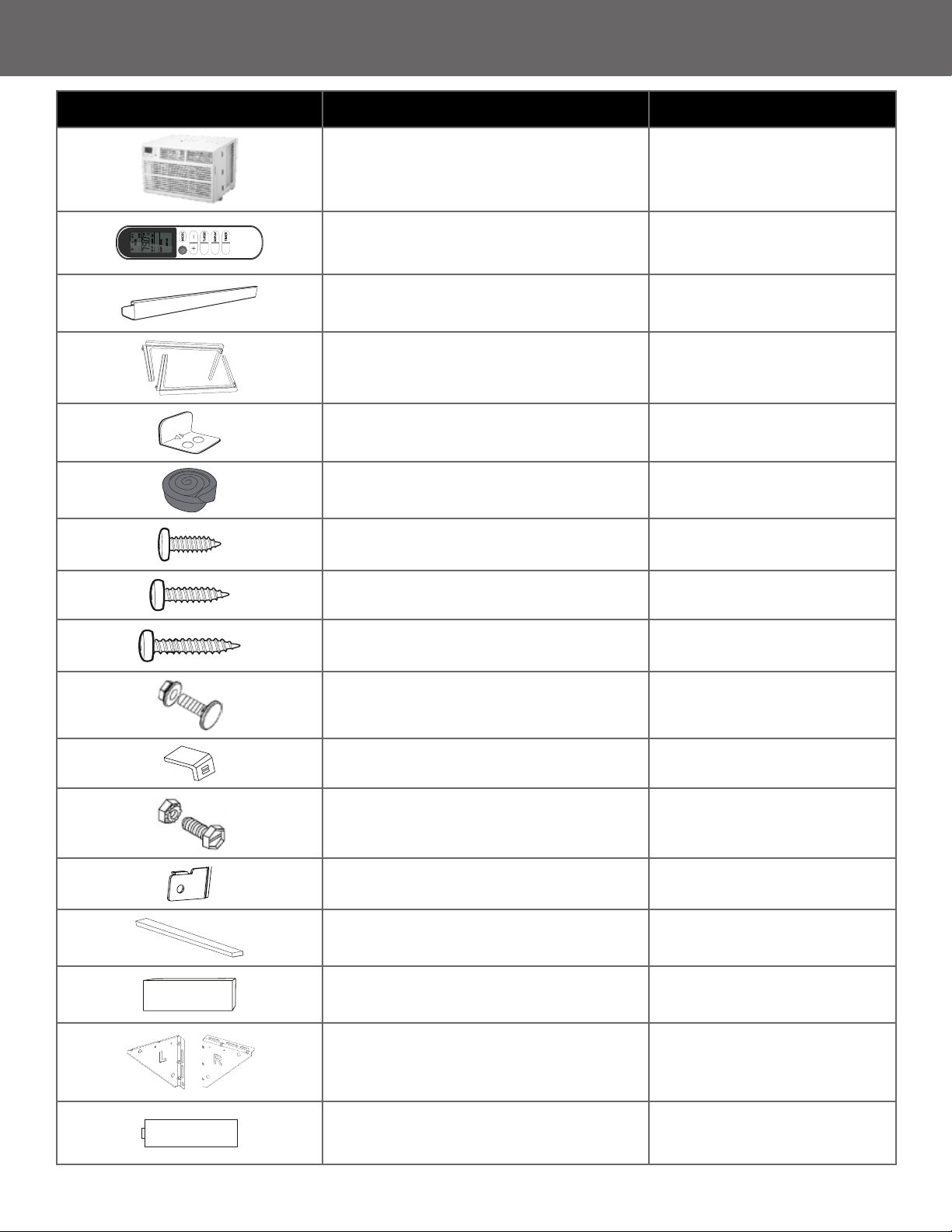
IMAGES PARTS QUANTITY
Window Air Conditioner
1
I FEEL
ECO
FAN
Remote Control
1
Top Mounting Rail (With sponge)
1
Accordion Panels
2
Sash Lock (Two holes)
1
Window Sash Seal (Sponge)
1
3/8″ Short Screws
5
1/2″ Length Screws
4
3/4″ Long Screws
3
5/8″ Big Flat Head Bolt
and Locknut
2
Sill Angel Bracket
2
1/2″ Small Flat Head Bolt
and Locknut
4
Chassis Lock
1
Foam Top Window Gasket
(Thin sponge for back-up using)
1
Insulation Strip (Sponge)
2
Support Bracket
(with R and L remark)
2
Battery
2
INSTALLATION & ASSEMBLY INSTRUCTIONS
6
DISCLAIMER
ALL INFORMATION AND THE TECHNICAL SPECIFICATIONS PRESENTED IN THIS USER’ S MANUAL ARE THE
PRESENTATION OF THE MANUFACTURE. PLEASE READ AND FOLLOW THESE INSTRUCTIONS CAREFULLY.
TOOLS NEEDED:
• Phillips Screw Driver
• Drill (If pilot holes are needed)
Window preparation
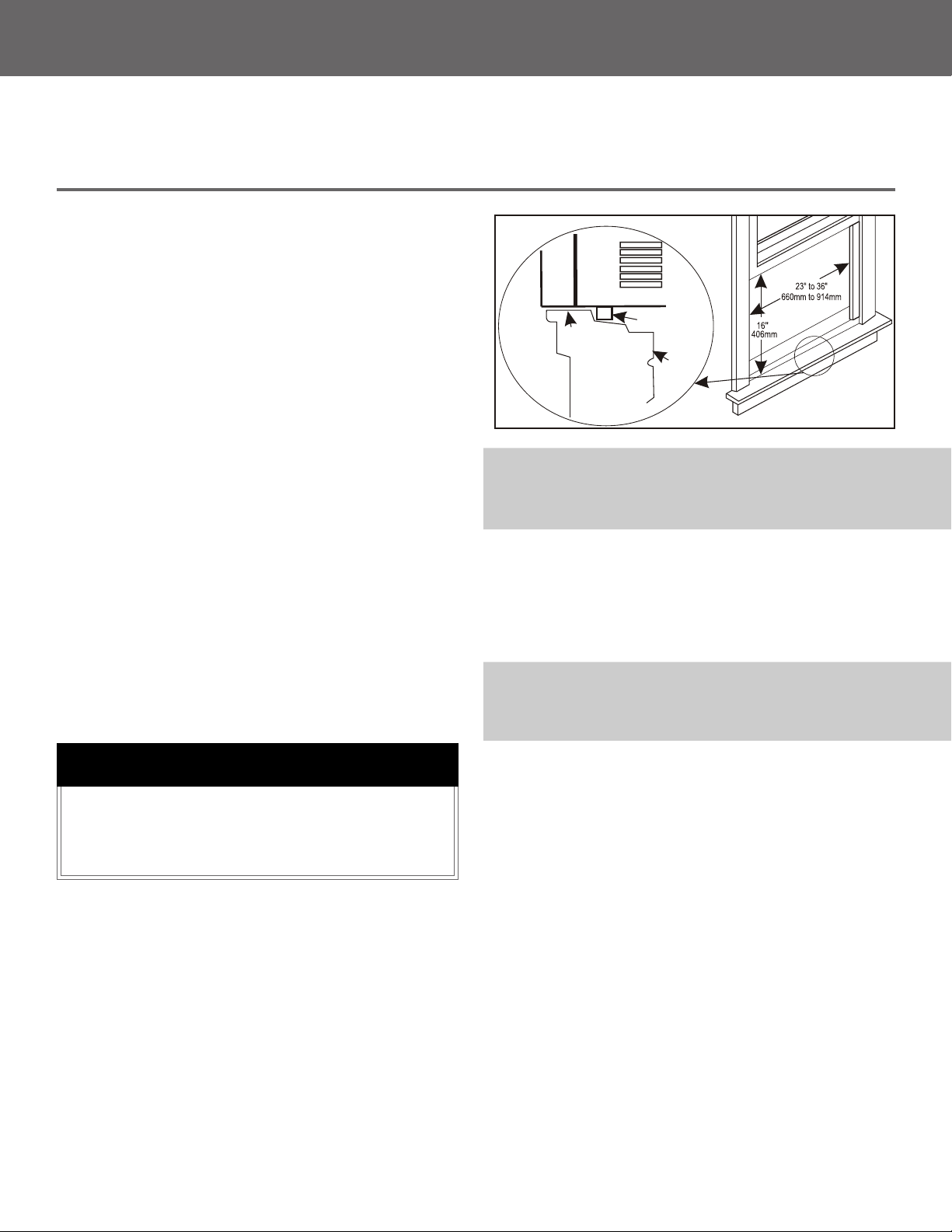
1. This air conditioner is designed to be installed In
a standard double-hung window with a window
width between 23″ and 36″ (660mm-914mm).
2. The air conditioner can be installed without the
accordion panels t in a narrow window opening.
3. The lower sash ( the lower part of the window
that moves up and down) must allow for 16” of
vertical clearance when open.
4. All supporting parts must be secured to rm
wood, masonry, or metal.
5. The electrical outlet must be within reach of the
power cord.
How to Install
NOTE: This is necessary for proper condensation utilization
and drainage. If you are not using the Side Panels for any
reason, this pitch to the rear must be maintained!
Remove the air conditioner from the box and place
it on a hard at surface, such as a oor, bench, or
table. There is a Left and Right Window Accordion
Panel - be sure to use the proper panel for each side.
When installed the ange for securing the panel in
place to the window sill will be facing into the room.
OFFSET
STOOL
SILL
INTERIOR
WALL
EXTERIOR
WALL
Air conditioner
Bottom channel
NOTE: Save the product packaging and installation instructions
for future reference. Store the air conditioner in the product
box when not in use for an extended period of time.
CAUTION
When handling unit, be careful to avoid cuts
from sharp metal edges and aluminum ns
on front and rear coils
.
INSTALLATION & ASSEMBLY INSTRUCTIONS
7
CONTINUED
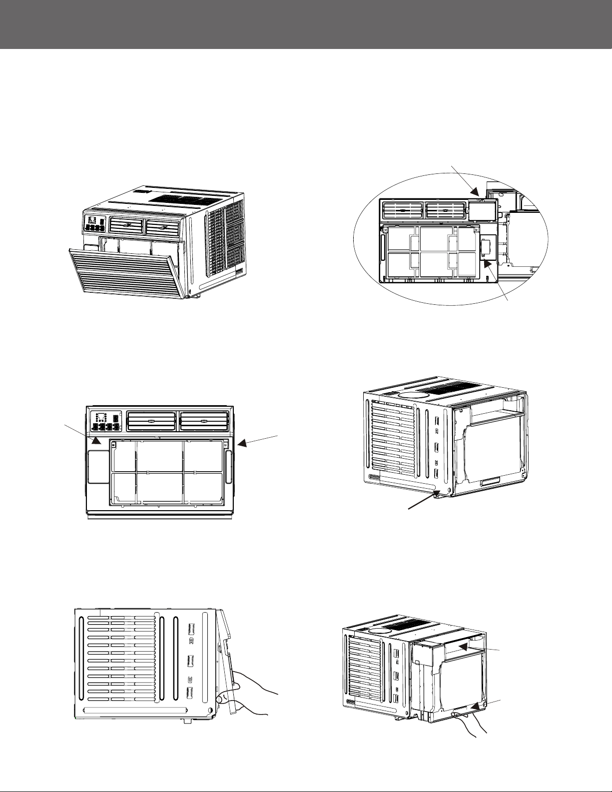
WINDOW MOUNTING
Remove Front Panel and Chassis
1. Pull down the front panel and remove the lter.
2. Lift the front panel upwards to remove and place
it to the side.
3. Locate the two faceplate screws and remove
them. These screws will need to be re-installed
before mounting the air conditioner.
4. After removing the screws, gently pull the
faceplate away from the air conditioner cabinet.
5. Remove the control panel screw and
WI-FI module screw (if available) from
the front panel.
6. Remove the screws from the cabinet.
Do not pull or lift
this area. It may
cause damage.
Pull the base handle.
7. Hold the cabinet while pulling on the base
handle to carefully remove the unit. Do not
pull or lift near the top of the unit.
INSTALLATION & ASSEMBLY INSTRUCTIONS
8
CONTINUED
WINDOW MOUNTING
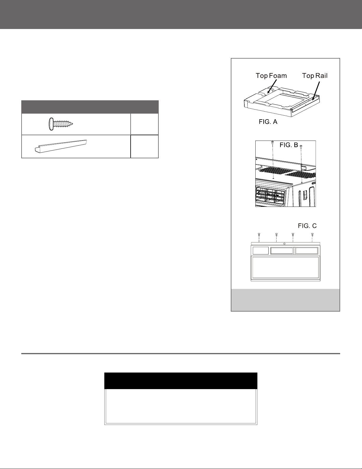
Top Rail Assembly
The top rail must be assembled prior to installing the air conditioner
in the window
Tools Needed: Phillips Screw Driver
Attaching the Top Rail to the Air Conditioner
1. Place the cabinet on a hard at surface.
2. Remove the top rail from the packaging material
as shown in FIG. A.
3. Align the hole in the top rail with those on the top
of the unit as shown in FIG. B.
4. Secure the top rail to the unit with the 3/8″ screws
as shown in FIG. C.
Top Rail Hardware QTY
3/8″
Screws
4
Top
Rail
1
NOTE: For safety reasons, all 4 screws
must be used to attach the top rail
CAUTION
When handling unit, be careful to avoid cuts
from sharp metal edges and aluminum ns
on front and rear coils
.
INSTALLATION & ASSEMBLY INSTRUCTIONS
9
CONTINUED
WINDOW MOUNTING
4. Use two or more people, place the air conditioner
into the window opening so the bottom of the air
conditioner frame is against the window sill.
Tilt the back of the unit slightly download to allow
accumulated rainwater to drain out.
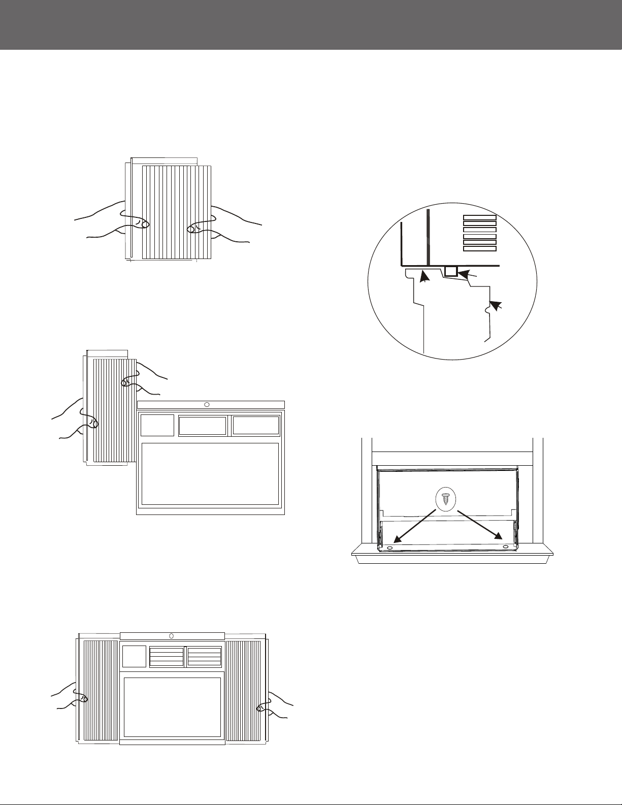
5. Fasten cabinet bottom to window sill using two
1/2″ screws. Pre-drill holes if needed.
Accordion Panel and cabinet Assembly
1. Hold the Accordion Panel in one hand and gently
pull the center to free the open end.
2. Slide the free end of the panel into the cabinet as
shown. Be sure to leave enough space to slip the
top and bottom of the frame into the rails on the
cabinet.
3. Once the panel has been installed on the side
of the cabinet, make sure it sits securely inside
the frame channel by making slight adjustments.
Slide the top and bottom ends of the frame into
the top and bottom rails of the cabinet. Slide the
panel out completely on both sides.
OFFSET
STOOL
SILL
INTERIOR
WALL
EXTERIOR
WALL
Air conditioner
Bottom channel
INSTALLATION & ASSEMBLY INSTRUCTIONS
10
CONTINUED
WINDOW MOUNTING
4. Tighten all the bolts with locknuts securely
Installing the Chassis into the Cabinet
1. Team lift (two people or more) the air conditioner
chassis and carefully slide it into the cabinet.
Let the front of the air conditioner hang out
approximately 6″.
2. CAUTION: DO NOT PUSH ON THE CONTROLS OR
FINNED COILS.
3. Be sure the chassis is rmly seated in the back
of the cabinet.
4. Insert all screws removed during window
installation and fasten, then reattach the front
faceplate, front panel, and the air lter.
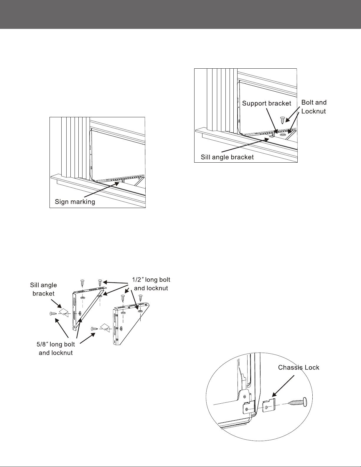
5. If the wall is too near to eect driving the cabinet
screw back, you can assemble the chassis lock
at the right bottom corner of the chassis with a
3/8″ screw as shown, before assembling the
front panel.
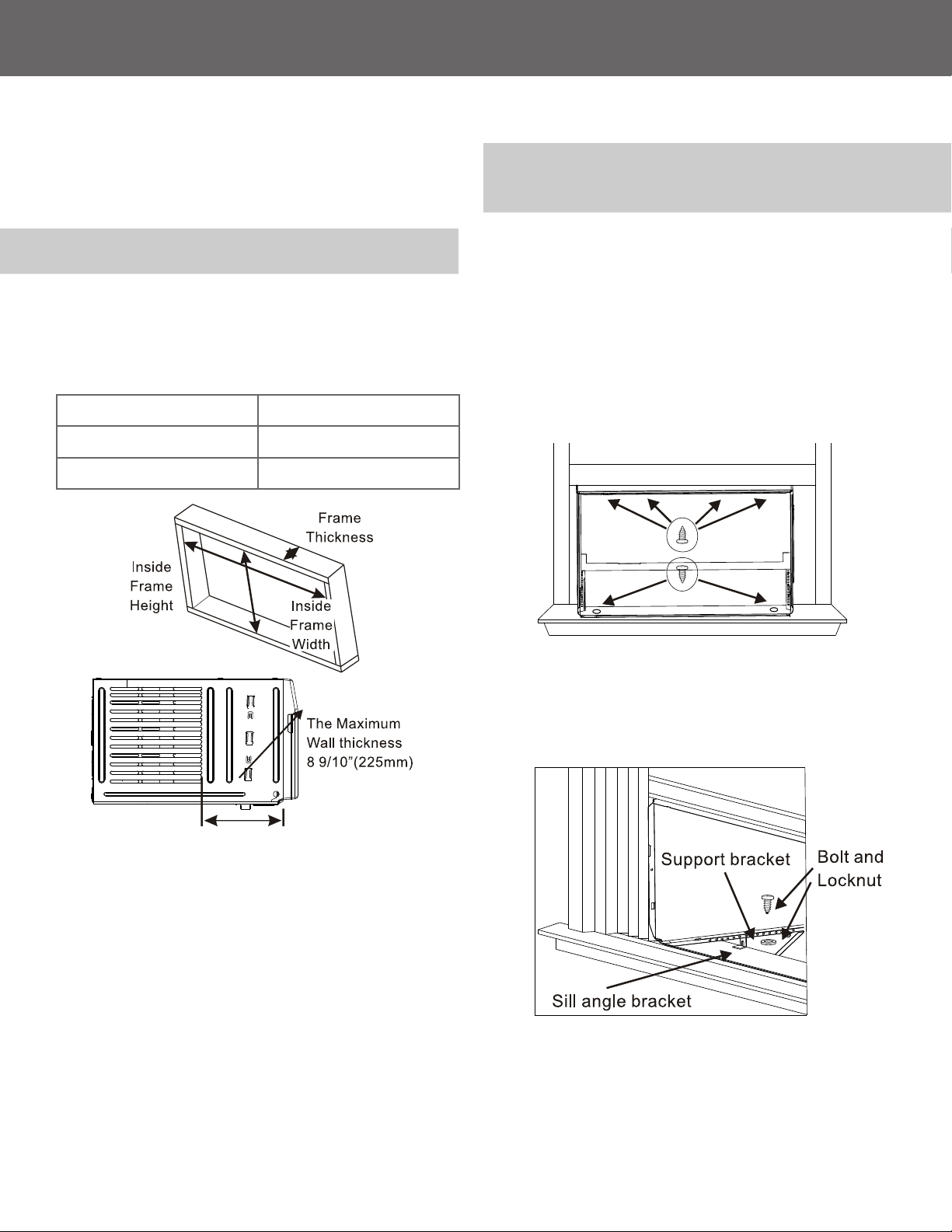
Install Support Brackets
1. Hold each support bracket ush against the
outside of the window sill. Tighten each bracket
to the bottom of the cabinet as shown. Mark the
brackets at the top level of the window sill and
then remove.
2. Assemble the sill angle brackets to the support
brackets at the marked position with long bolt
and locknut as shown. Hand tighten, but not for
any changes that may need to be made later
during installation.
3. Install the support brackets (with sill angle
brackets) to the bottom of the cabinet as shown.
INSTALLATION & ASSEMBLY INSTRUCTIONS
11
CONTINUED
WINDOW MOUNTING
Installing the Chassis into the Cabinet
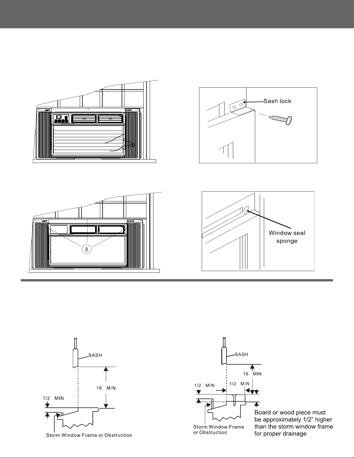
6. Extend the side accordion panels out against
the window frame as shown.
Storm Window Requirements
A storm window frame will not allow the air conditioner to tilt properly which in turn will keep it from draining
properly. To adjust for this, attach a board or piece of wood to the sill. The board or wood piece should have
a depth of at least 1/2″. Make sure the board or piece of wood is approximately 1/2″ higher than the storm
window frame. This will allow the air conditioner to tilt enough for proper drainage.
7. Drive 1/2″ locking screws through frame holes,
and drive one 3/4″ screw through the top rail
into window sash as shown.
8. To secure lower sash in place, attach right angle
sash lock with 3/4″ screws as shown.
9. Cut foam seal and insert in the space between
the upper and lower sashes as shown.
THROUGH-THE-WALL INSTALLATION INSTRUCTIONS
12
OPTIONAL
Install Support Brackets
The case may be installed through-the-wall as
optional. Read completely, then follow step-by-step.
NOTE: Obtain all materials locally for mounting the air
conditioner through-the-wall.
IMPORTANT
Building a wooden frame is required when installing
the case through-the-wall. The opening and
dimension of the wooden frame should match the
dimensions below.
Through-the-wall installation is not appropriate if any of the
side or top louvers of the case are obstructed by the wall.
All side and top louvers must project from the outdoor side
of the wall.
The room side of the case must project into the room far
enough to maximize the balance of the unit.
The case must be installed level from side to side and with
a slight tilt from front to rear. Use a level to conrm no more
than a 1/2 bubble space is slanted to the outside.
Lintel angle is required to support bricks or blocks above
the opening.
Flashing is required and should extend the length of the
opening to ensure no inside cavity leakage occurs.
Frame Max. Thickness 8 9/10″ (225 mm)
Inside Frame Width 20″ (508 mm)
Inside Frame Height 15-1/5″ (385 mm)
NOTE: The allowed maximum wall thickness is less than
8 9/10". Otherwise, the wall will block the air inlet on the
outdoor side, it will effect the normal operation of the unit.
1. Build a wooden frame into the wall opening and
fasten securely.
2. Remove the air conditioner from the box and
remove the chassis cover.
3. Place the cabinet into the wooden frame and
lock the cabinet by the top rail hole and bottom
chassis hole with 1" long wood screws as shown
from inside to outside. (screws not included)
5. Assemble the chassis into the cabinet and fasten
or lock it following window mounting installation
instructions.
4. Assemble the two Support Bracket with Sill Angle
Bracket to the cabinet against the wooden frame
as window mounting installation instructions.
USING YOUR AIR CONDITIONER
13
Electronic Control Panel & Remote Control
NOTE: This display always shows the room temperature in
Fan Mode except when setting the Timer.
Normal Operating Sounds
• You may hear a pinging noise caused by water
hitting the condenser on rainy days, or when
the humidity is high. This design feature helps
remove moisture and improve eciency.
• You may hear the thermostat click when the
compressor cycles on and o.
• Water will collect in the base pan during rain or
days of high humidity. The water may overow
and drip from the outside part of the unit.
• The fan may run even when the compressor is
not on.
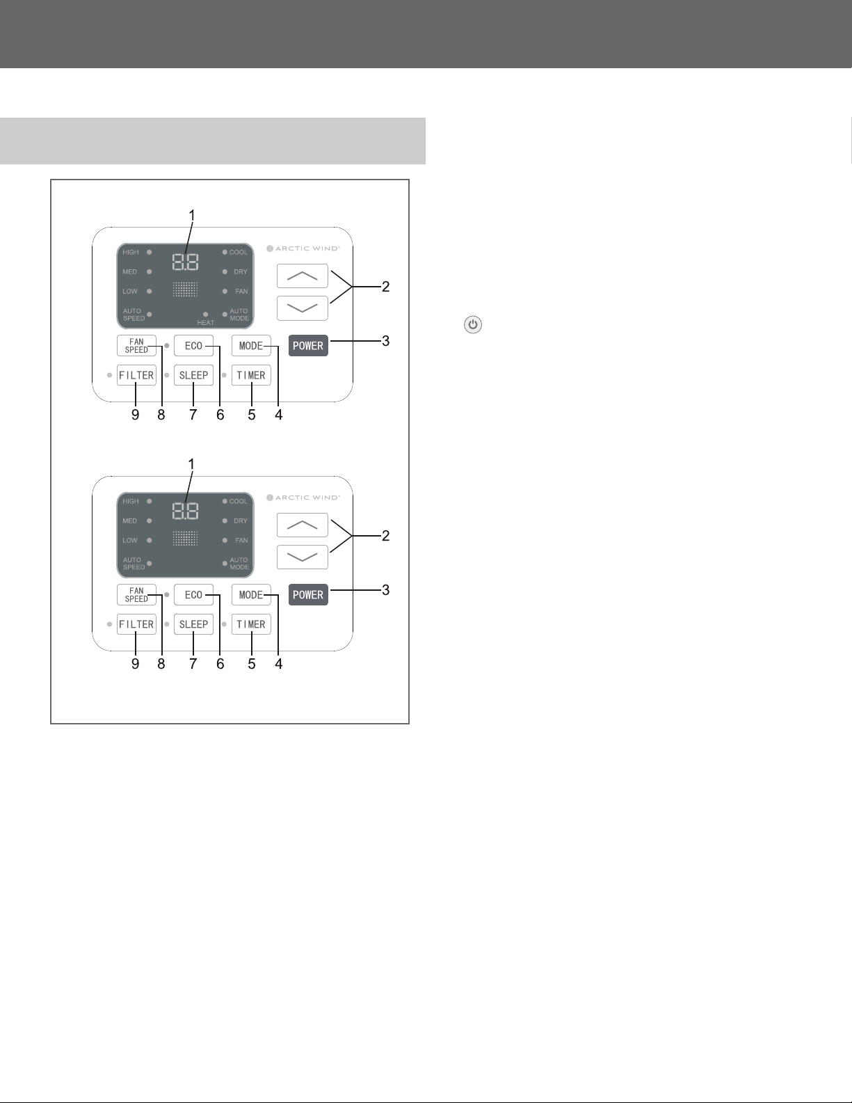
1.
Digital Display: Without timer setting, the set
temperature will be displayed. Time will be
displayed under the timer setting.
2.
+ and - Button: Use these buttons on the
control panel and remote to increase or
decrease the Set Temperature or Timer.
Temperature range: 61ºF~88ºF or 16ºC~31ºC.
3.
Button: Turn the air conditioner on and o.
4.
Mode Button: Press the mode button to cycle
through the various modes: Cool, Dry, Fan
and Auto, or Heat.
Cool Mode: The cooling function allows the air
conditioner to cool the room and at the same
time reduces air humidity. Press the MODE
button to activate the cooling function. To
optimize the function of the air conditioner,
adjust the temperature and the speed by
pressing the button indicated.
Dry Mode: This function reduces the humidity
of the air to make the room more comfortable.
Press MODE button to set the DRY mode. An
automatic function of alternating cooling cycles
and air fan is activated.
Fan Mode: The conditioner works in only
ventilation. Press MODE button to set the FAN
mode. With pressing the FAN SPEED button the
speed changes in the following sequence: Hi,
Med and Lo in FAN mode.
Auto Mode: In AUTO mode the unit automatically
chooses the fan speed and the mode of
operation (COOL, HEAT, DRY or FAN). In this
mode the temperature are set automatically
according to the room temperature (tested by
the temperature sensor which is incorporated in
the indoor unit.).
Heat Mode: The heating function allows the air
conditioner to heat the room. Press the MODE
button to activate the heating function. To
optimize the function of the air conditioner,
adjust the temperature and the speed by
pressing the button indicated.
Air Conditioner Controls
Cooling Model
For Heating Model For
USING YOUR AIR CONDITIONER
14
CONTINUED
Electronic Control Panel & Remote Control
5. Timer Button: Use these buttons on the control
panel and remote to set the Timer.
Timer Off: The timed stop is programmed by pressing
TIMER button. Set the rest time by pressing the
button
+ or - until the rest time displayed is to your
liking then press the TIMER button again.
Timer On: When the unit is o, press TIMER button
at the rst time, set the temperature with pressing
the button
+ or -. Press TIMER button at the
second time, set the rest time with pressing the
button
+ or -. Press TIMER button at the third
time, conrm the setting, then the rest time to next
automatical switching-on could be read on the
display of the machine.
Note: It can be set to automatically turn off or on in 0.5-
24 hours. Each press of the “+” “-” buttons will increase
or
decrease the timer. The Timer can be set in 0.5 hours
increment
below 10 hours and 1 hour increment for 10
hours or above. The SET light will turn on while setting.
To cancel the set function, press the TIMER button again.
6.
Eco Mode Button: When the unit is in Eco mode,
the light will turn on. In Eco mode, the unit
will turn o once the room is cooled to the
temperature set by the user. The unit will turn
back on when the room temperature rises above
the set temperature. Before the compressor
starts, the fan motor will run for a while, then it
will stop for a while. It will repeat to provide a
more comfortable environment and save energy.
7.
Sleep Button: Press the SLEEP button, all the
display lights will turn o after a while, but the
SLEEP light is always on. In SLEEP mode, the
air conditioner will automatically adjust the
temperature and fan speed to make the room
more comfortable during the night. The set
temperature will automatically change every
30-60 minutes and at most change six times
until the setting temperature is 81ºF or 82ºF
for cooling mode and 75ºF or 76ºF for heating
mode.
8.
Fan Speed Button:
Press the FAN SPEED button
to choose the fan speed options. You can choose
Hi, Med, Lo or auto speed in COOL or HEAT
mode and choose Hi, Med, Lo in FAN mode.
9. Filter Button: The Filter Check light will turn on
to remind the user to clean the lter after the fan
motor runs for 500 total hours. Turn o the light
by pressing the Filter Check button.
10.
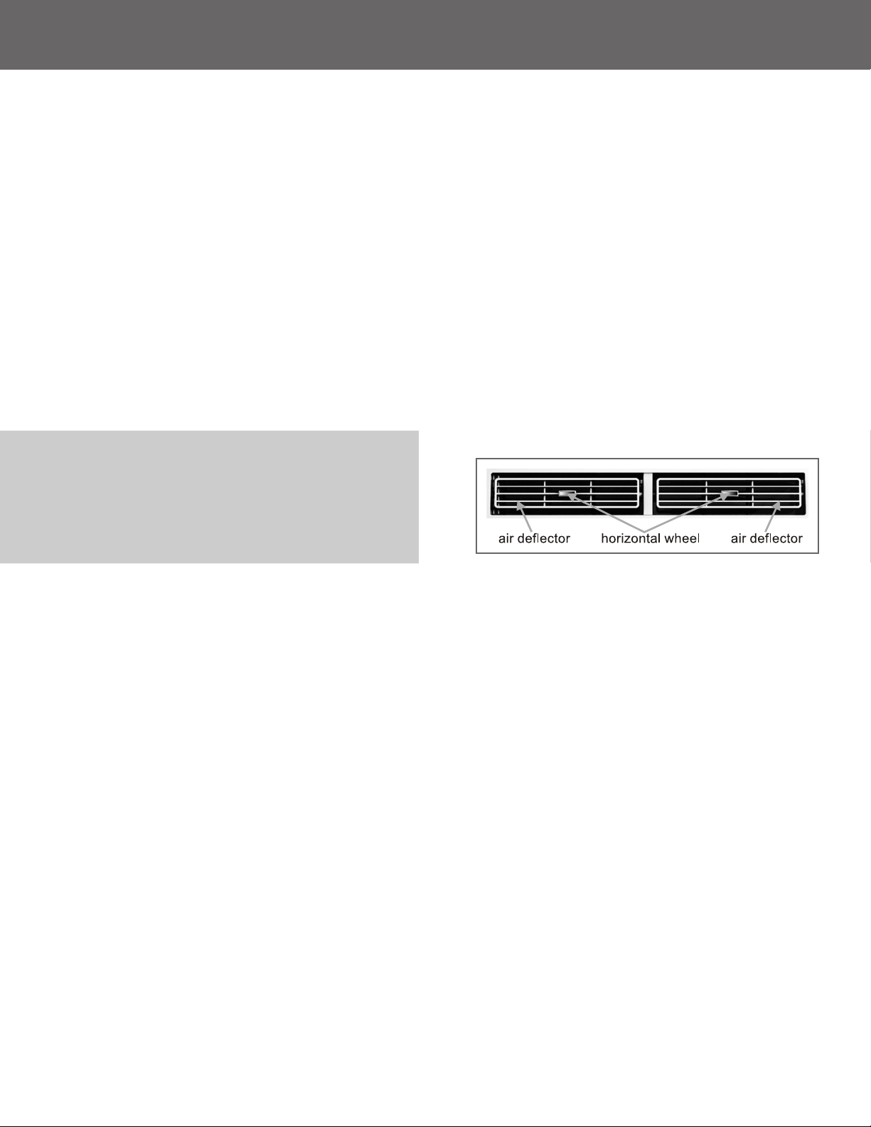
Directional Louvers: The horizontal wheels control
the horizontal airow, the air deectors control
the vertical airow.
OPERATING YOUR AIR CONDITIONER
15
REMOTE CONTROL
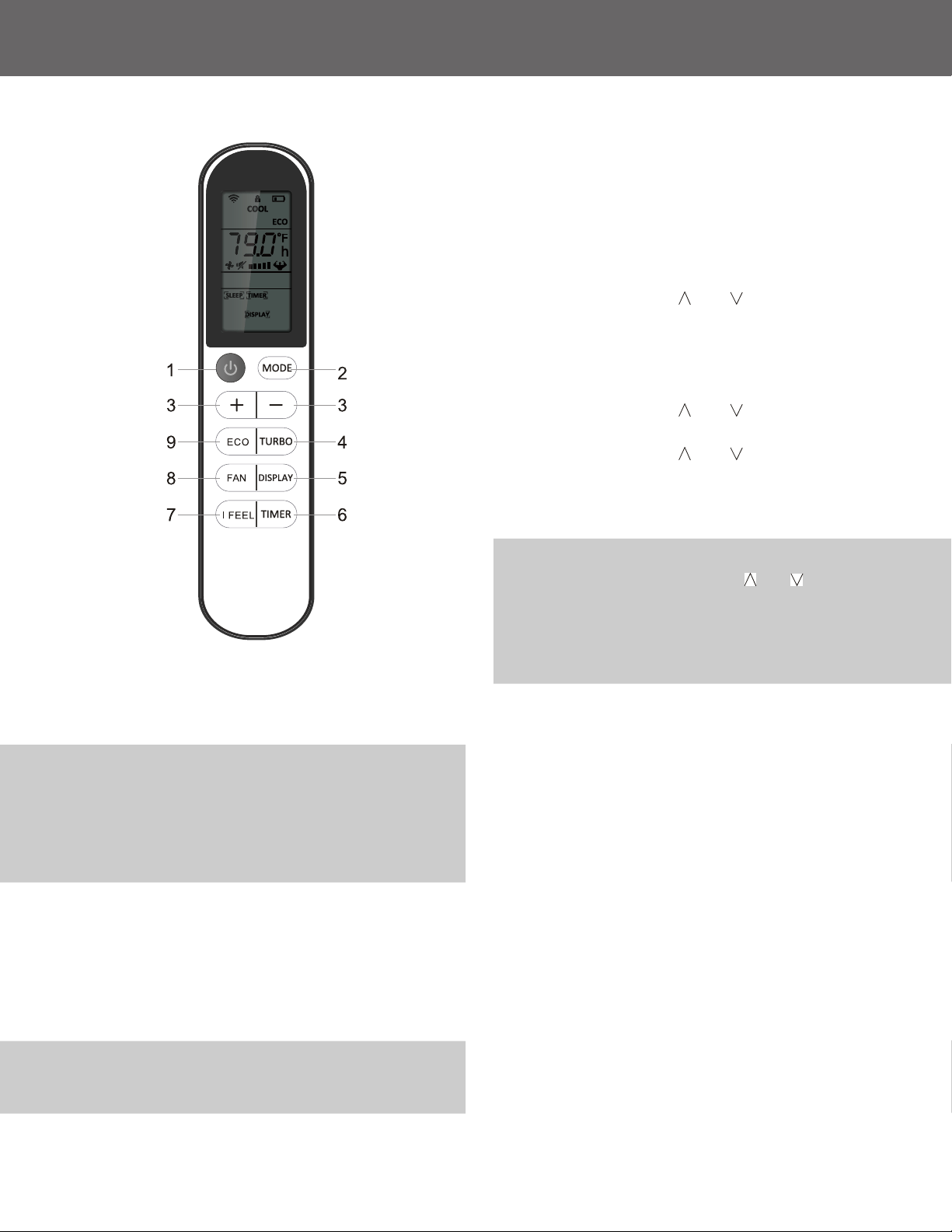
1. POWER: Turn the air conditioner on and o.
2.
MODE: Press the button to select the mode of
operation, AUTO, COOL, DRY, FAN, HEAT.
Note:
The HEAT mode is only for some heating models. If
you do not need it, press the MODE button for more than
5 seconds to delete the HEAT function, and the COOL mode
will be selected automatically. Press the MODE again for
more than 5 seconds to add the HEAT function, and the
HEAT mode will be selected automatically.
3. + and - : Use these buttons to increase or
decrease the Set Temperature or Timer.
Temperature range: 61ºF~88ºF or 16ºC ~31ºC .
4.
TURBO: When the remote is ON, press the button
to activate the TURBO function, under AUTO/
COOL/FAN/HEAT mode.
Note:
ºF and ºC change: Press TURBO button for more than
5 seconds to switch the ºF and ºC degree display. This
should be done within 3 minutes of inserting the batteries.
5. DISPLAY: To press the DISPLAY button, it can
switch o/on all lights or LED display.
6.
TIMER: Use these buttons on the control panel
and remote to set the Timer.
Timer Off: The timed stop is programmed by
pressing TIMER button. Set the rest time by
pressing the button “
” or “ ” until the rest
time you want is displayed, then press TIMER
button again.
Timer On: When the unit is o, press TIMER
button one time and set the temperature by
pressing the button “
” or “ ”. Press TIMER
button a second time to set the rest time by
pressing the button “
” or “ ”. Press TIMER
button a third time to conrm the setting, then
the countdown to the next automatic “on” cycle
will be displayed.
Note:
The timer can be set to automatically turn off or on
in 0.5-24 hours. Each press of the “
” or “ ” buttons will
increase or decrease the timer. The Timer can be set in 0.5
hours increment below 10 hours and 1 hour increment for
10 hours or above. The SET light will turn on while setting.
To cancel the set function, press the TIMER button again.
7. I FEEL: Press the button to activate the remote
thermostat function. The function enables the
remote to measure the temperature at its current
location and send a signal to the air conditioner
to optimize the temperature around you.
8.
FAN: Press the FAN SPEED button to choose
the fan speed options. You can choose Hi, Med,
Low, or auto speed in COOL mode and choose
Hi, Med, Lo in FAN mode.
9.
ECO: When the unit is in ECO mode, the light
will turn on. In ECO mode, the unit will turn
o once the room is cooled to the user set
temperature. The unit will turn back on when
the room temperature rises above the user
set temperature. Before the compressor starts
the fan motor will keep running for a while and
stop for a while and again to provide a more
comfortable feeling and save energy.
Battery Size: AAA - NOTE: Do not mix old and new batteries or dierent types of AAA batteries
CARE AND CLEANING
16
Clean your air conditioner to keep it looking new
and to minimize dust build-up.
Air Filter Cleaning
The air lter should be checked at least once
every month to see if it needs cleaning. Trapped
particles and dust can build up in the lter and
may decrease airow as well as cause the cooling
coils to accumulate frost. To clean the air lter:
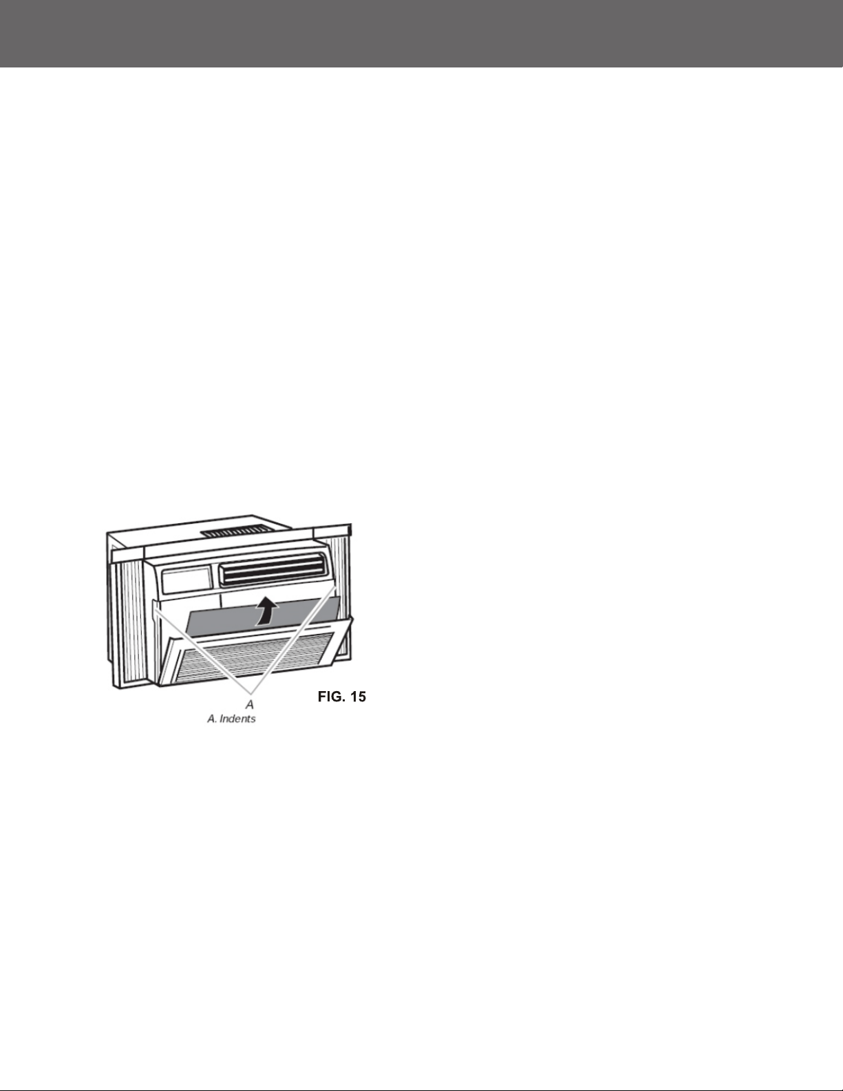
1. Remove the lter by pulling down on the
indents of the lter door on the front of the
unit. (See FIG. 15 )
2. Wash the lter using liquid dish soap and
warm water. Rinse the lter thoroughly. Gently
shake the lter to remove excess water.
3. Let the lter dry completely before placing it
into the air conditioner.
4. If you do not wish to wash the lter, you
may vacuum the lter to remove the dust
and other particles.
Cabinet Cleaning
To clean the air conditioner cabinet:
• Unplug the air conditioner to prevent shock or a
re hazard. The cabinet and front panel of the air
conditioner may be dusted with an oil free cloth
or washed with a cloth dampened in a solution
of warm water and mild liquid soap. Rinse
thoroughly with a damp cloth and wipe dry.
• Never use harsh cleaners, wax, or polish on the
cabinet front.
• Be sure to wring excess water from the cloth
before wiping around the controls. Excess water
in or around the controls may cause damage to
the air conditioner.
Winter Storage
To store the air conditioner when it is not in use for
an extended period, remove it carefully from the
window according to the installation instructions and
cover it with plastic or place it in the original box.
ATTENTION:
To minimize wear and tear on the air conditioner
always wait at least 3 minutes before changing
modes. This will help prevent the compressor from
overheating and the circuit breaker from tripping.
TROUBLESHOOTING
17
PROBLEM POSSIBLE CAUSES SOLUTIONS
The Air Conditioner
will not start
The air conditioner is unplugged • Make sure the air conditioner
plug is pushed completely into
the outlet
The fuse is blown/circuit breaker
is tripped.
• Check the house fuse/circuit
breaker box and replace the
fuse or reset the breaker.
Power failure • The unit will automatically
re-start when power is restored.
• There is a protective time delay
(approx. 3 minutes) to prevent
tripping of the compressor
overload. For this reason,
the unit may not start normal
cooling for 3 minutes after it is
turned back on.
The current interrupter device
is tripped.
• Press the RESET button located
on the power cord plug.
• If the RESET button will not stay
engaged, discontinue the use of
the air conditioner and contact
a qualied service technician.
The Air Conditioner
does not cool as it should
Airow is restricted • Make sure there are no curtains,
blinds, or furniture blocking the
front of the air conditioner
The temperature control
may not be set correctly.
• Lower the set thermostat
temperature
The air lter is dirty • Clean the lter. See the Cleaning
and Care section of the manual.
The room may be too warm • Please allow time for the room
to cool down after turning on
the air conditioner.
Cold air is escaping • Check for open furnace
registers and cold air returns
The cooling coils are frozen • See “Air Conditioner Freezing
Up” below.
TROUBLESHOOTING
18
CONTINUED
PROBLEM POSSIBLE CAUSES SOLUTIONS
The Air Conditioner
is freezing up
Ice blocks the airow and stops
the air conditioner from cooling
the room
• Set the MODE dial to HIGH
FAN or HIGH COOL and set
the thermostat to a higher
temperature
The Remote Control
is not working
The batteries are inserted
incorrectly
• Check the position of the
batteries.
The batteries may be dead • Replace the batteries
Water is dripping outside
Hot and humid weather. • This is normal
Water is dripping
inside the room
The air conditioner is not
correctly tilted outside.
• For proper water drainage,
make sure the air conditioner is
slightly tilted downward from the
front of the unit to the rear.
Water collects
in the base pan
Moisture removed from the air
is draining into the base pan.
• This is normal for a short period
in areas with low humidity and
nor mal for a longer period in
areas with high humidity.

5401 Dansher Road
Countryside, IL 60525
Printed in China | 0121_M528