Operator's Manual
CRRFTSMRN
18 Gauge
¾ - 11/4"Length
BRAD NAILER
Model No.
351.184090
CAUTION: Read and follow
all Safety Rules and Operating
Instructions before First Use
of this Product.
Sears, Roebuck and Co., Hoffman Estates, IL 60179 U.S.A.
• Safety
• Operation
• Maintenance
• Parts List
• Espa5ol
4348.01 Draft (11/02/99)
Warranty ....................................... 2
Safety Rules .................................... 2
Operation .................................... 2-4
Maintenance .................................... 4
Troubleshooting ................................. 5
Parts Illustration and List ......................... 6-7
EspaSol ..................................... 8-11
FULL ONE YEAR WARRANTY ON CRAFTSMAN
AIR-DRIVE TOOLS
If this Craftsman air-drive tool fails due to a defect in material
or workmanship within one full year from the date of
purchase, return it to the nearest Sears Service Center in the
United States, and Sears will repair it free of charge.
If this air-drive tool is used for commercial purposes, this war-
ranty applies for only 90 days from the date of purchase.
This warranty gives you specific legal rights and you may also
have other rights which vary from state to state.
Sears, Roebuck and Co., Dept. 817WA, Hoffman Estates, IL
60179
• Air tool operators and all others in work area should
always wear safety goggles complying with United States
ANSI Z87.1 to prevent eye injury from fasteners and flying
debris when loading, operating or unloading this tool.
• Never exceed operating pressure of 100 PSI.
• Always keep hands and body away from the fastener dis-
charge area when air supply is connected to tool.
• Always disconnect tool from air supply when servicing or
adjusting tool and when tool is not in use.
• Do not operate when contact trip is not in contact with
work.
• Never load the tool until you are ready to use it.
• Never depress tool trigger when loading.
• Always load with nose of tool pointing away from you and
others.
• Never point tool at yourself or others.
• Never carry tool with trigger depressed.
• Do not use oxygen, combustible gas or high pressure
compressed gas as the air supply for the tool.
• Always use tool at safe distance from other people in work
area.
• Do not attempt to discharge fastener into hard or brittle
materials such as concrete, steel or tile.
• Do not connect female quick-disconnect coupling to tool
side of air line.
• Connect male, free-flow nipple to tool side of air line so
that tool is depressurized when hose is disconnected.
• Do not use a hose swivel with this tool.
• Use Sears recommended fasteners only.
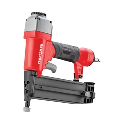
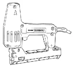
DESCRIPTION
The Craftsman 18 Gauge Brad Nailer drives brads from 3/8"to
1_/4"long. Oilless design eliminates daily oiling and oil stains
on workpiece. Die cast aluminum body with textured grip mini-
mizes operator fatigue. Large capacity, side loading magazine
with positive, quick action latch makes loading easy. Safety
feature disables tool unless contact trip is pressed against
workpiece. Tapered nosepiece provides operator with greater
visibility for precise fastener placement. Rigid nosepiece
reduces jamming. The 18 Gauge Brad Nailer is excellent for
molding, furniture making, and picture framing.
SPECIFICATIONS
Capacity ............................. 110 brad nails
Nail size ..................... 18 gauge (.049" x .040")
Nail lengths ............................... % to 1_"
Operating pressure ....................... 60-100 PSI
Air inlet .................................. '/4" N.ET.
Length ....................................... 9"
Height ....................................... 7_ ''
Width ........................................ 2"
Weight ..................................... 2 Ibs.
BRAD NAILS
18341 .................... 18 gauge brad nails, %" long
18342 .................... 18 gauge brad nails, 1" long
18343 ................... 18 gauge brad nails, 1'/4" long
AIR SUPPLY LINE
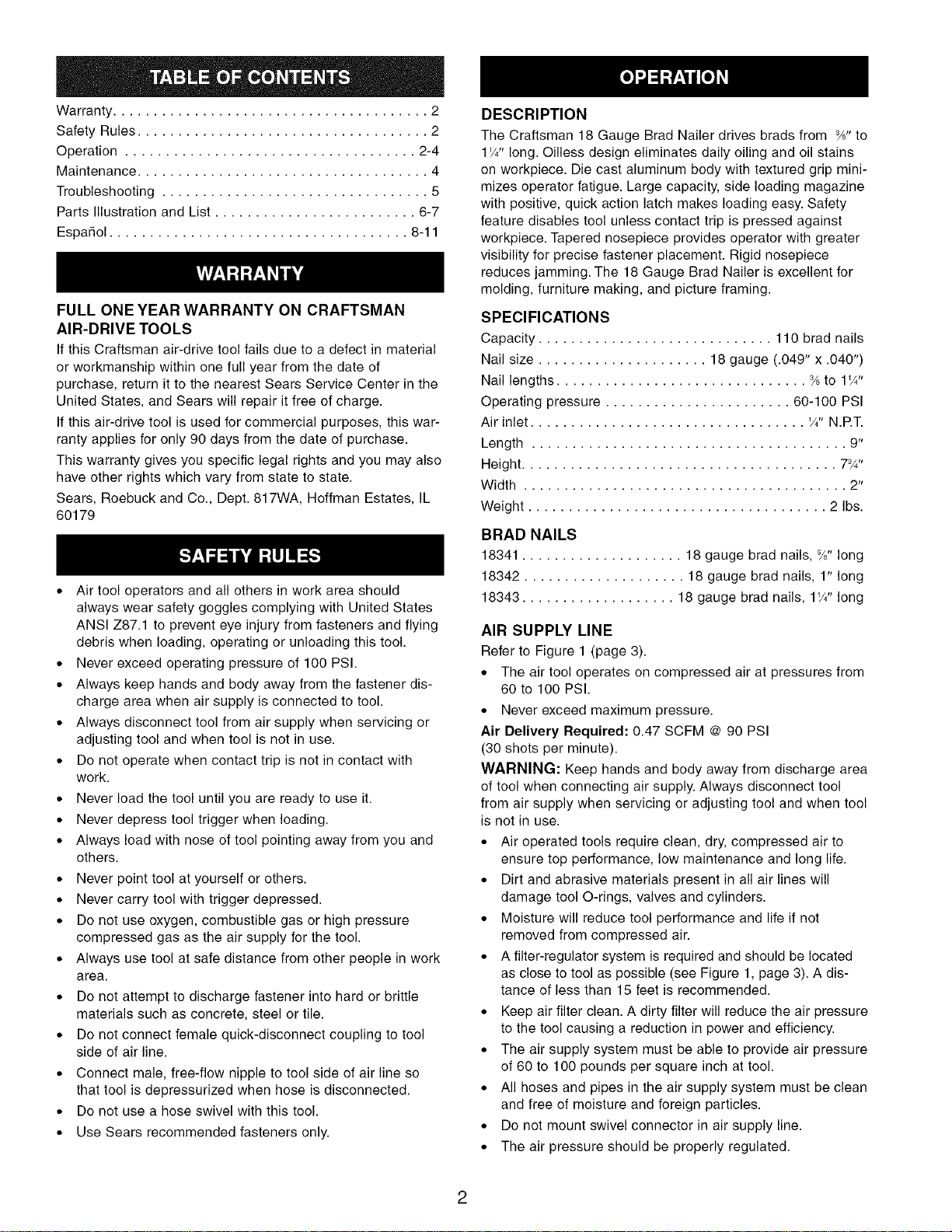
Refer to Figure 1 (page 3).
° The air tool operates on compressed air at pressures from
60 to 100 PSI.
° Never exceed maximum pressure.
Air Delivery Required: 0.47 SCFM @ 90 PSI
(30 shots per minute).
WARNING: Keep hands and body away from discharge area
of tool when connecting air supply. Always disconnect tool
from air supply when servicing or adjusting tool and when tool
is not in use.
° Air operated tools require clean, dry, compressed air to
ensure top performance, low maintenance and long life.
° Dirt and abrasive materials present in all air lines will
damage tool O-rings, valves and cylinders.
° Moisture will reduce tool performance and life if not
removed from compressed air.
° A filter-regulator system is required and should be located
as close to tool as possible (see Figure 1, page 3). A dis-
tance of less than 15 feet is recommended.
° Keep air filter clean. A dirty filter will reduce the air pressure
to the tool causing a reduction in power and efficiency.
° The air supply system must be able to provide air pressure
of 60 to 100 pounds per square inch at tool.
° All hoses and pipes in the air supply system must be clean
and free of moisture and foreign particles.
° Do not mount swivel connector in air supply line.
° The air pressure should be properly regulated.
2
* Different workpiece materials and different fastener
lengths will require different operating pressure.
* Be sure all connections in air supply system are sealed to
prevent air loss.
* Never connect a female quick-disconnect coupling to the
tool side of air line connection. A male, free-flow coupling
should be connected to the tool side of air line connection.
WARNING: The female coupling provides a seal preventing
loss of compressed air from compressor tank when discon-
nected from male coupling. If connected to tool side of air
supply, the female coupling could seal a compressed air
charge in the tool which could discharge if the tool trigger is
actuated.
2 Foot Hose Whip_
Male Quick-Disconnect
Figure 1 - Air Supply Line
Filter - Regulator
o
1 °°
Female Quick-Disconnect
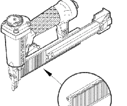
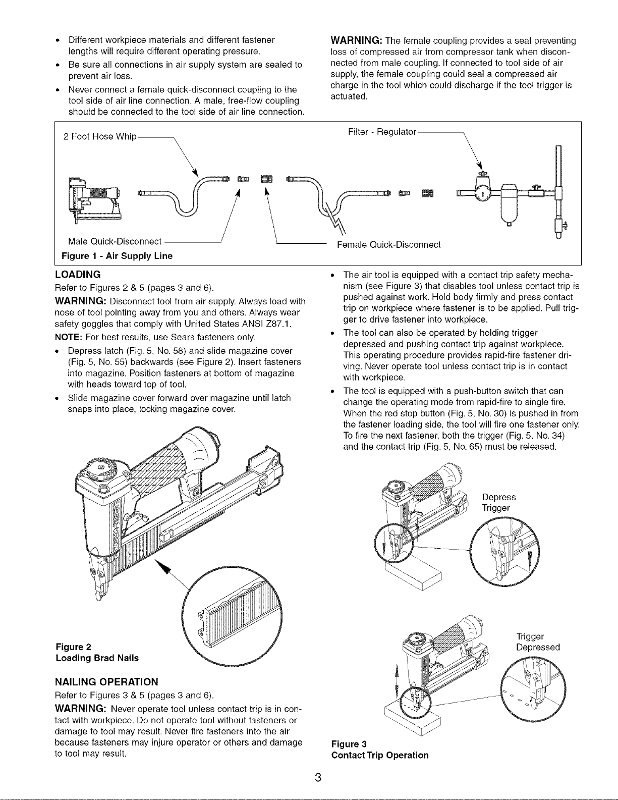
LOADING
Refer to Figures 2 & 5 (pages 3 and 6).
WARNING: Disconnect tool from air supply. Always load with
nose of tool pointing away from you and others. Always wear
safety goggles that comply with United States ANSI Z87.1.
NOTE: For best results, use Sears fasteners only.
. Depress latch (Fig. 5, No. 58) and slide magazine cover
(Fig. 5, No. 55) backwards (see Figure 2). Insert fasteners
into magazine. Position fasteners at bottom of magazine
with heads toward top of tool.
. Slide magazine cover forward over magazine until latch
snaps into place, locking magazine cover.
(
° The air tool is equipped with a contact trip safety mecha-
nism (see Figure 3) that disables tool unless contact trip is
pushed against work. Hold body firmly and press contact
trip on workpiece where fastener is to be applied. Pull trig-
ger to drive fastener into workpiece.
° The tool can also be operated by holding trigger
depressed and pushing contact trip against workpiece.
This operating procedure provides rapid-fire fastener dri-
ving. Never operate tool unless contact trip is in contact
with workpiece.
° The tool is equipped with a push-button switch that can
change the operating mode from rapid-fire to single fire.
When the red stop button (Fig. 5, No. 30) is pushed in from
the fastener loading side, the tool will fire one fastener only.
Tofire the next fastener, both the trigger (Fig. 5, No. 34)
and the contact trip (Fig. 5, No. 65) must be released.
Depress
Trigger
Figure 2
Loading Brad Nails
NAILING OPERATION
Refer to Figures 3 & 5 (pages 3 and 6).
WARNING: Never operate tool unless contact trip is in con-
tact with workpiece. Do not operate tool without fasteners or
damage to tool may result. Never fire fasteners into the air
because fasteners may injure operator or others and damage
to tool may result.
Figure 3
Contact Trip Operation
Trigger
Depressed
OPERATINGPRESSURE
o Use only enough air pressure to perform the operation. Air
pressure in excess of that which is required will make the
operation inefficient and may cause premature wear or
damage to the tool.
o Determine minimum air pressure required by driving some
test fasteners into the workpiece. Set air pressure so that
test fasteners are driven down flush with the work surface.
Fasteners driven too deep may damage workpiece.
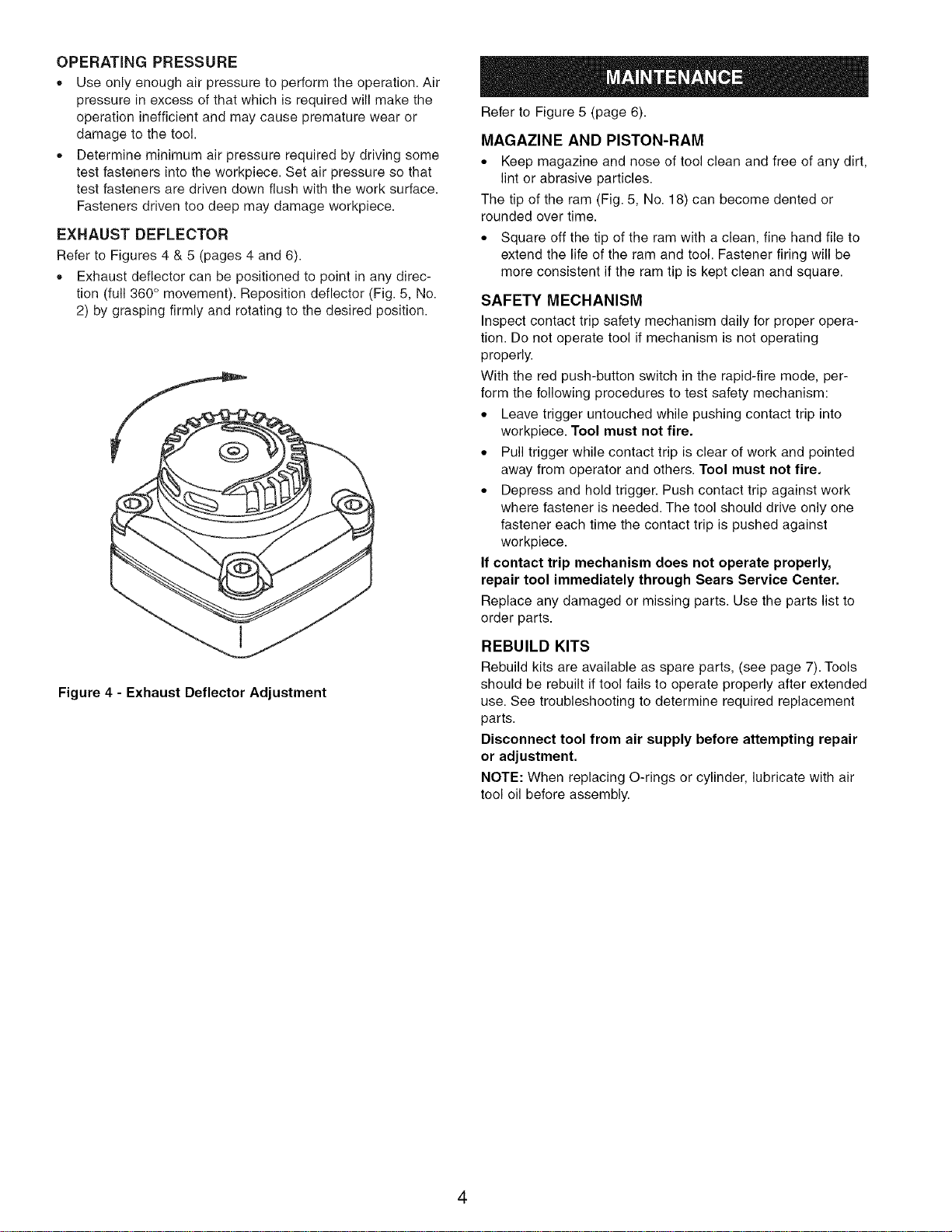
EXHAUST DEFLECTOR
Refer to Figures 4 & 5 (pages 4 and 6).
o Exhaust deflector can be positioned to point in any direc-
tion (full 360 ° movement). Reposition deflector (Fig. 5, No.
2) by grasping firmly and rotating to the desired position.
Figure 4 - Exhaust Deflector Adjustment
Refer to Figure 5 (page 6).
MAGAZINE AND PISTON-RAM
° Keep magazine and nose of tool clean and free of any dirt,
lint or abrasive particles.
The tip of the ram (Fig. 5, No. 18) can become dented or
rounded over time.
• Square off the tip of the ram with a clean, fine hand file to
extend the life of the ram and tool. Fastener firing will be
more consistent if the ram tip is kept clean and square.
SAFETY MECHANISM
Inspect contact trip safety mechanism daily for proper opera-
tion. Do not operate tool if mechanism is not operating
properly.
With the red push-button switch in the rapid-fire mode, per-
form the following procedures to test safety mechanism:
• Leave trigger untouched while pushing contact trip into
workpiece. Tool must not fire.
• Pull trigger while contact trip is clear of work and pointed
away from operator and others. Tool must not fire.
• Depress and hold trigger. Push contact trip against work
where fastener is needed. The tool should drive only one
fastener each time the contact trip is pushed against
workpiece.
If contact trip mechanism does not operate properly,
repair tool immediately through Sears Service Center.
Replace any damaged or missing parts. Use the parts list to
order parts.
REBUILD KITS
Rebuild kits are available as spare parts, (see page 7). Tools
should be rebuilt if tool fails to operate properly after extended
use. See troubleshooting to determine required replacement
parts.
Disconnect tool from air supply before attempting repair
or adjustment.
NOTE: When replacing O-rings or cylinder, lubricate with air
tool oil before assembly.
4
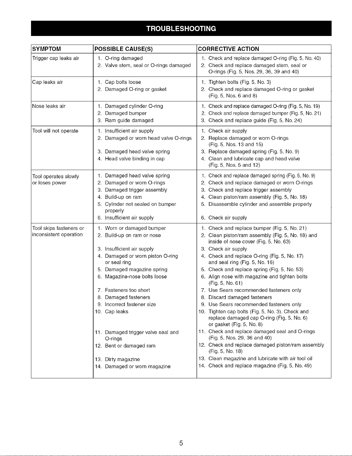
SYMPTOM POSSIBLE CAUSE(S) CORRECTIVE ACTION
Trigger cap leaks air 1. O-ring damaged 1. Check and replace damaged O-ring (Fig. 5, No.40)
2. Valve stem, seal or O-rings damaged 2. Check and replace damaged stem, seal or
O-rings (Fig. 5, Nos. 29, 36, 39 and 40)
Cap leaks air 1. Cap bolts loose 1. Tighten bolts (Fig. 5, No. 3)
2. Damaged O-ring or gasket 2. Check and replace damaged O-ring or gasket
(Fig. 5, Nos. 6 and 8)
Nose leaks air 1. Damaged cylinder O-ring 1. Check and replace damaged O-ring (Fig. 5, No. 19)
2. Damaged bumper 2. Check and replace damaged bumper (Fig. 5, No. 21)
3. Ram guide damaged 3. Check and replace guide (Fig. 5, No. 24)
Tool will not operate
Tool operates slowly
or loses power
Tool skips fasteners or
inconsistent operation
1,
2.
Insufficient air supply 1.
Damaged or worn head valve O-rings 2.
3. Damaged head valve spring
4. Head valve binding in cap
1. Damaged head valve spring
2. Damaged or worn O-rings
3. Damaged trigger assembly
4. Build-up on ram
5. Cylinder not sealed on bumper
properly
6. Insufficient air supply
1.
2.
Worn or damaged bumper
Build-up on ram or nose
3. Insufficient air supply
4. Damaged or worn piston O-ring
or seal ring
5. Damaged magazine spring
6. Magazine-nose bolts loose
7. Fasteners too short
8. Damaged fasteners
9. Incorrect fastener size
10. Cap leaks
11. Damaged trigger valve seal and
O-rings
12. Bent or damaged ram
13. Dirty magazine
14. Damaged or worn magazine
3,
4.
Check air supply
Replace damaged or worn O-rings
(Fig. 5, Nos. 13 and 15)
Replace damaged spring (Fig. 5, No. 9)
Clean and lubricate cap and head valve
(Fig. 5, Nos. 5 and 12)
1. Check and replace damaged spring (Fig. 5, No. 9)
2. Check and replace damaged or worn O-rings
3. Check and replace trigger assembly
4. Clean piston/ram assembly (Fig. 5, No. 18)
5. Disassemble cylinder and assemble properly
6,
1.
2.
Check air supply
Check and replace bumper (Fig. 5, No. 21)
Clean piston/ram assembly (Fig. 5, No. 18) and
inside of nose cover (Fig. 5, No. 63)
3. Check air supply
4. Check and replace O-ring (Fig. 5, No. 17)
and seal ring (Fig. 5, No. 16)
5. Check and replace spring (Fig. 5, No. 53)
6. Align nose with magazine and tighten bolts
(Fig. 5, No. 61)
7. Use Sears recommended fasteners only
8. Discard damaged fasteners
9. Use Sears recommended fasteners only
10. Tighten cap bolts (Fig. 5, No. 3). Check and
replace damaged cap O-ring (Fig. 5, No. 6)
or gasket (Fig. 5, No. 8)
11. Check and replace damaged seal and O-rings
(Fig. 5, Nos. 29, 36 and 40)
12. Check and replace damaged piston/ram assembly
(Fig. 5, No. 18)
13. Clean magazine and lubricate with air tool oil
14. Check and replace magazine (Fig. 5, No. 49)
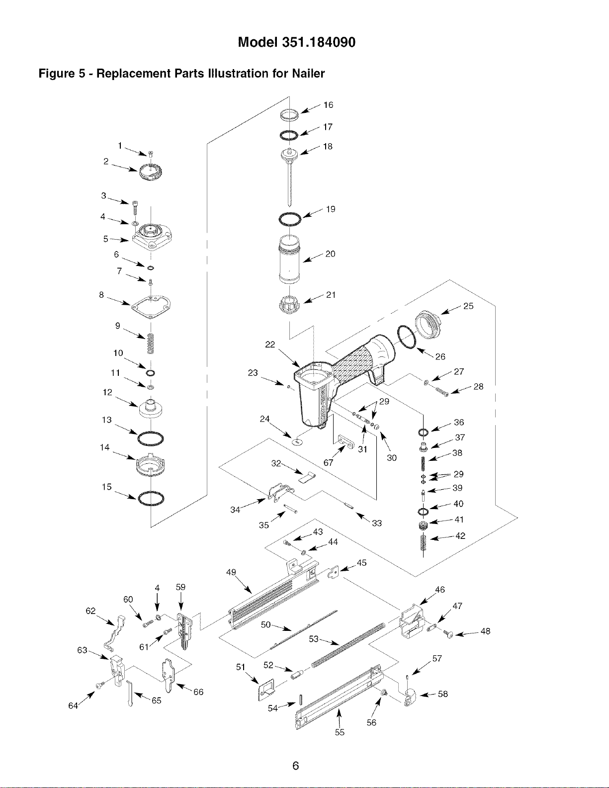
Model 351.184090
Figure 5 - Replacement Parts Illustration for Nailer
_16
18
1
2
6 (
11 0
12
13
14
4 59
_._ 20
23
49
\
\
47
58
56
55
6
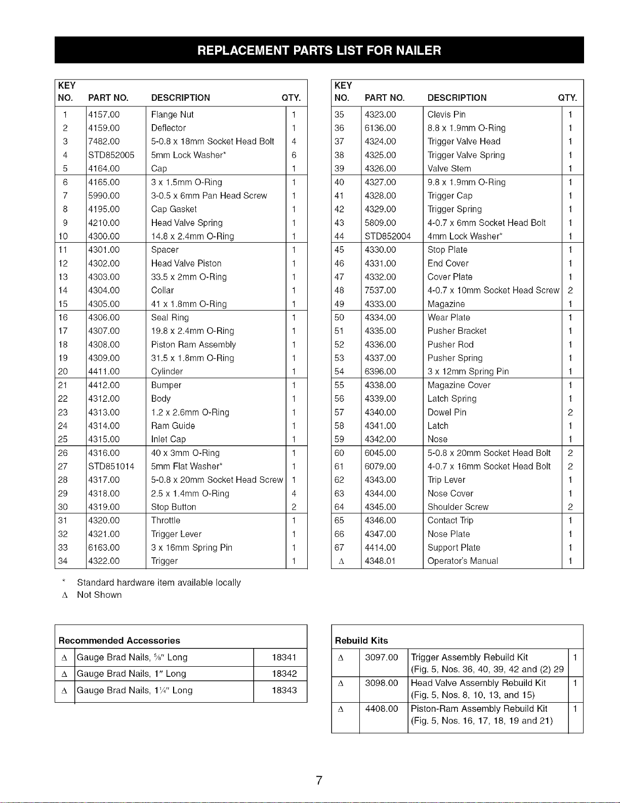
KEY
NO. PART NO.
1 4157.00
2 4159.00
3 7482.00
4 STD852005
5 4164.00
6 4165.00
7 5990.00
8 4195.00
9 4210.00
10 4300.00
11 4301.00
12 4302.00
13 4303.00
14 4304.00
15 4305.00
16 4306.00
17 4307.00
18 4308.00
19 4309.00
20 4411.00
21 4412.00
22 4312.00
23 4313.00
24 4314.00
25 4315.00
26 4316.00
27 STD851014
28 4317.00
29 4318.00
30 4319.00
31 4320.00
32 4321.00
33 6163.00
34 4322.00
DESCRIPTION QTY.
Flange Nut 1
Deflector 1
5-0.8 x 18mm Socket Head Bolt 4
5mm Lock Washer* 6
Cap 1
3 x 1.5mm O-Ring 1
3-0.5 x 6mm Pan Head Screw 1
Cap Gasket 1
Head Valve Spring 1
14.8 x 2.4ram O-Ring 1
Spacer 1
Head Valve Piston 1
33.5 x 2ram O-Ring 1
Collar 1
41 x 1.8mm O-Ring 1
Seal Ring 1
19.8 x 2.4ram O-Ring 1
Piston Ram Assembly 1
31.5 x 1.8mm O-Ring 1
Cylinder 1
Bumper 1
Body 1
1.2 x 2.6mm O-Ring 1
Ram Guide 1
Inlet Cap 1
40 x 3mm O-Ring 1
5mm Flat Washer* 1
5-0.8 x 20mm Socket Head Screw 1
2.5 x 1.4mm O-Ring 4
Stop Button 2
Throttle 1
Trigger Lever 1
3 x 16mm Spring Pin 1
Trigger 1
* Standard hardware item available locally
A Not Shown
Recommended Accessories
A Gauge Brad Nails, %" Long 18341
A Gauge Brad Nails, 1" Long 18342
A Gauge Brad Nails, 1'/4" Long 18343
KEY
NO. PART NO.
35 4323.00
36 6136.00
37 4324.00
38 4325.00
39 4326.00
40 4327.00
41 4328.00
42 4329.00
43 5809.00
44 STD852004
45 4330.00
46 4331.00
47 4332.00
48 7537.00
49 4333.00
50 4334.00
51 4335.00
52 4336.00
53 4337.00
54 6396.00
55 4338.00
56 4339.00
57 4340.00
58 4341.00
59 4342.00
60 6045.00
61 6079.00
62 4343.00
63 4344.00
64 4345.00
65 4346.00
66 4347.00
67 4414.00
A 4348.01
DESCRIPTION QTY.
Clevis Pin 1
8.8 x 1.9ram O-Ring 1
Trigger Valve Head 1
Trigger Valve Spring 1
Valve Stem 1
9.8 x 1.9ram O-Ring 1
Trigger Cap 1
Trigger Spring 1
4-0.7 x 6mm Socket Head Bolt 1
4mm Lock Washer* 1
Stop Plate 1
End Cover 1
Cover Plate 1
4-0.7 x 10mm Socket Head Screw 2
Magazine 1
Wear Plate 1
Pusher Bracket 1
Pusher Rod 1
Pusher Spring 1
3x 12ram Spring Pin 1
Magazine Cover 1
Latch Spring 1
Dowel Pin 2
Latch 1
Nose 1
5-0.8 x 20mm Socket Head Bolt 2
4-0.7 x 16mm Socket Head Bolt 2
Trip Lever 1
Nose Cover 1
Shoulder Screw 2
Contact Trip 1
Nose Plate 1
Support Plate 1
Operator's Manual 1
Rebuild Kits
A 3097.00 Trigger Assembly Rebuild Kit 1
(Fig. 5, Nos. 36, 40, 39, 42 and (2) 29
A 3098.00 Head Valve Assembly Rebuild Kit 1
(Fig. 5, Nos. 8, 10, 13, and 15)
A 4408.00 Piston-Ram Assembly Rebuild Kit 1
(Fig. 5, Nos. 16, 17, 18, 19 and 21)
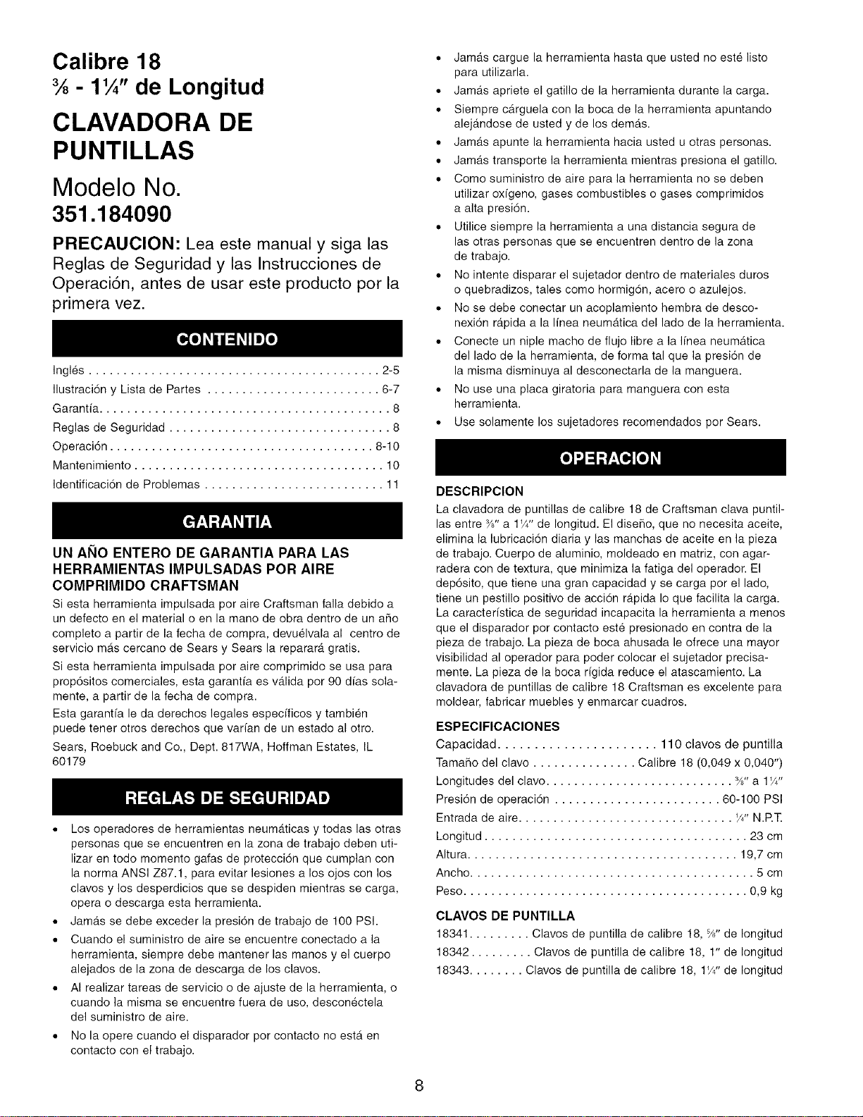
Calibre 18
% - 1¼" de Longitud
CLAVADORA DE
PUNTILLAS
Modelo No.
351.184090
PRECAUCION: Lea este manual y siga las
Reglas de Seguridad y las Instrucciones de
Operaci6n, antes de usar este producto por la
primera vez.
Ingles .......................................... 2-5
IlustraciTn y Lista de Partes ......................... 6-7
Garanfia .......................................... 8
Reglas de Seguridad ................................ 8
Operaci6n ...................................... 8-10
Mantenimiento .................................... 10
IdentificaciTn de Problemas .......................... 11
UN AI_IO ENTERO DE GARANTIA PARA LAS
HERRAMIENTAS IMPULSADAS POR AIRE
COMPRIMIDO CRAFTSMAN
Siesta herramienta impulsadapor aire Craftsman falla debido a
un defecto en el material o en la mano de obra dentro de un afro
completo a partir de la fecha de compra, devuelvala al centro de
servicio mas cercano de Sears y Sears la reparar_,gratis.
Siesta herramienta impulsada por aire comprimido se usa para
prop6sitos comerciales, esta garanfia es v_.lida por 90 dfas sola-
mente, a partir de la fecha de compra.
Esta garanfia le da derechos legales especfficos y tambien
puede tenet otros derechos que varian de un estado al otro.
Sears, Roebuck and Co., Dept. 817WA, Hoffman Estates, IL
60179
• Los operadores de herramientas neum_.ticas y todas las otras
personas que se encuentren en la zona de trabajo deben uti-
lizar en todo momento gafas de protecci6n que cumplan con
la norma ANSI Z87.1, para evitar lesiones a los ojos con los
clavos y los desperdicios que se despiden mientras se carga,
opera o descarga esta herramienta.
• Jam_.s se debe exceder la presi6n de trabajo de 100 PSI.
,, Cuando el suministro de aire se encuentre conectado a la
herramienta, siempre debe mantener las manos y el cuerpo
alejados de la zona de descarga de los clavos.
,, AI realizar tareas de servicio o de ajuste de la herramienta, o
cuando la misma se encuentre fuera de uso, desconectela
del suministro de aire.
• No la opere cuando el disparador por contacto no esta en
contacto con el trabajo.
• Jamas cargue la herramienta hasta que usted no este listo
para utilizarla.
• Jam_.s apriete el gatillo de la herramienta durante la carga.
• Siempre carguela con la boca de la herramienta apuntando
alejandose de usted y de los demas.
• Jamas apunte la herramienta hacia usted u otras personas.
• Jam_.s transporte la herramienta mientras presiona el gatillo.
• Como suministro de aire para la herramienta no se deben
utilizar oxigeno, gases combustibles o gases comprimidos
a alta presi6n.
• Utilice siempre la herramienta a una distancia segura de
las otras personas que se encuentren dentro de la zona
de trabajo.
• No intente disparar el sujetador dentro de materiales duros
o quebradizos, tales como hormig6n, acero o azulejos.
• No se debe conectar un acoplamiento hembra de desco-
nexi6n rapida a la linea neum6.tica del lado de la herramienta.
,, Conecte un niple macho de flujo libre a la Ifnea neumatica
del lado de la herramienta, de forma tal que la presi6n de
la misma disminuya al desconectarla de la manguera.
• No use una placa giratoria para manguera con esta
herramienta.
,, Use solamente los sujetadores recomendados por Sears.
DESCRIPCION
La clavadora de puntillas de calibre 18 de Craftsman clava puntil-
las entre -_8"a 1W' de Iongitud. El diseho, que no necesita aceite,
elimina la lubricaci6n diaria y las manchas de aceite en la pieza
de trabajo. Cuerpo de aluminio, moldeado en matriz, con agar-
radera con de textura, que minimiza la fatiga del operador. El
dep6sito, que tiene una gran capacidad y se carga pot el lado,
tiene un pestillo positivo de acciTn rApida Io que facilita la carga.
La caracterfstica de seguridad incapacita la herramienta a menos
que el disparador por contacto este presionado en contra de la
pieza de trabajo. La pieza de boca ahusada le ofrece una mayor
visibilidad al operador para poder colocar el sujetador precisa-
mente. La pieza de la boca rigida reduce el atascamiento. La
clavadora de puntillas de calibre 18 Craftsman es excelente para
moldear, fabricar muebles y enmarcar cuadros.
ESPEClFICAClONES
Capacidad ...................... 110 clavos de puntilla
Tamaffo del clavo ............... Calibre 18 (0,049 x 0,040")
Longitudes del clavo ........................... %" a 1W'
Presi6n de operaci6n ........................ 80-100 PSI
Entrada de aire ............................... '/4" N.P.T.
Longitud ...................................... 23 cm
AItura ....................................... 19,7 cm
Ancho ......................................... 5 cm
Peso ......................................... 0,9 kg
CLAVOS DE PUNTILLA
18341 ......... Clavos de puntilla de calibre 18, %" de Iongitud
18342 ......... Clavos de puntilla de calibre 18, 1" de Iongitud
18343 ........ Clavos de puntilla de calibre 18, 1W' de Iongitud
8
LINEA DE SUMINISTRO DE AIRE
Refierase a la Figura 1 (pagina 9).
,. La herramienta de aire opera con aire comprimido a pre-
siones desde 60 hasta 100 PSI.
,0 Jamas se debe exceder la presi6n maxima.
Suministro de aire requerido: 0,47 SCFM a 90 PSI
(30 disparos por minuto).
ADVERTENClA: Mientras conecta el suministro de aire se
deben mantener las manos y el cuerpo alejados de la zona de
descarga de la herramienta. Siempre se debe desconectar
el suministro de aire de la herramienta mientras se realizan
tareas de servicio o ajuste de la misma, o cuando esta no se
encuentra en uso.
,. Para asegurar rendimiento maximo, bajo mantenimiento y
larga vida las herramientas con accionamiento neumatico
requieren aire comprimido, limpio y seco.
,. La suciedad y los materiales abrasivos presentes en las
lineas neumaticas pueden daSar los anillos O, las valvulas
y los cilindros de la herramienta.
,0 Si la humedad no se elimina del aire comprimido, se reduce
el rendimiento y la vida de la herramienta.
,. Se requiere un sistema de filtro-regulador, el cual se debe
colocar tan cerca de la herramienta como sea posible (yea le
Figura 1, pagina 9). Recomendamos una distancia no mayor
a4,6 m.
•, Mantenga limpio el fiitro de aire. Un filtro sucio reduce la pre-
si6n de aire que se suministra al clavador y provoca una
reducci6n de la potencia y la eficiencia.
,, El sistema de suministro de aire debe ser capaz de proveer
una presi6n de aire de 60 a 100 PSI en la herramienta.
,, Todas las mangueras y tuber[as del sistema de suministro
de aire deben estar limpias y libres de humedad y part[culas
extraSas.
,, En la I[nea de suministro de aire no se debe colocar un
conector giratorio.
,, La presi6n de aire se debe ajustar apropiadamente.
•, Los distintos materiales de la pieza de trabajo y las distin-
tas longitudes de los clavos requieren distintas presiones
de operaci6n.
,, AsegOrese de que todas las conexiones del sistema neu-
matico esten bien selladas para evitar fugas de aire.
•, Jamas se debe conectar un acople hembra de desconexi6n
rapida en el lado de la herramienta del suministro neumatico.
Se debe conectar un acople macho de flujo libre a la Ifnea
neumatica del lado de la herramienta.
ADVERTENClA: El acoplamiento hembra proporciona un selIo
que evita la perdida del aire comprimido del estanque del com-
presor cuando esta desconectado del acoplamiento macho. Si
esta conectado al lado de la herramienta del abastecimiento de
aire, el acoplamiento hembra puede sellar una carga de aire
comprimido en la herramienta que se puede descargar en el
caso de que el accionador de la herramienta se active.
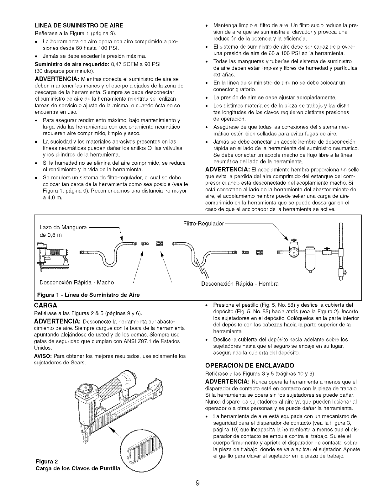
Lazo de Manguera -\
de 0,6 m
Desconexi6n R
Filtro-Regulador
Desconexi6n Rapida - Hembra
Figura 1 - Linea de Suministro de Aire
CARGA
Refierase a las Figuras 2 & 5 (paginas 9 y 6).
ADVERTENCIA: Desconecte la herramienta del abaste-
cimiento de aire. Siempre cargue con la boca de la herramienta
apuntando alejandose de usted y de los demas. Siempre use
gafas de seguridad que cumplan con ANSI Z87.1 de Estados
Unidos.
AVISO: Para obtener los mejores resultados, use solamente los
sujetadores de Sears.
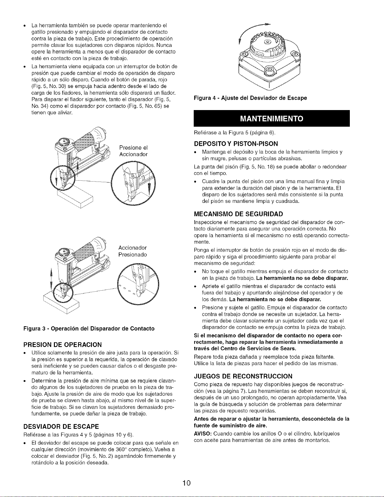
Figura 2
Carga de los Clavos
,, Presione el pestilIo (Fig. ,5, No. 58) y deslice la cubierta del
dep6sito (Fig. 5, No. 55) hacia atras (vea la Figura 2). Inserte
los sujetadores en el dep6sito. Col6quelos en la parte inferior
del dep6sito con las cabezas hacia la parte superior de la
herramienta.
,, Deslice la cubierta del dep6sito hacia adelante sobre los
sujetadores hasta que el seguro se encaje en su lugar,
asegurando la cubierta del dep6sito.
OPERACION DE ENCLAVADO
Refierase alas Figuras 3 y 5 (paginas 10 y 6).
ADVERTENClA: Nunca opere la herramienta a menos que el
disparador de contacto este en contacto con la pieza de trabajo.
Si la herramienta se opera sin los sujetadores se puede daSar.
Nunca dispare los sujetadores al aire ya que pueden lesionar al
operador o a otras personas y se puede da5ar la herramienta.
,, La herramienta de aire esta equipada con un mecanismo de
seguridad para el disparador de contacto (vea la Figura 3,
pagina 10) que incapacita la herramienta a menos que el dis-
parador de contacto se empuje contra el trabajo. Sujete el
cuerpo firmemente y apriete el disparador de contacto sobre
la pieza de trabajo, donde se va a aplicar el sujetador. Apriete
el gatiIIo para clavar el sujetador en la pieza de trabajo.
Laherramientatambi@nsepuedeoperarmanteniendoel
gatillopresionadoyempujandoeldisparadordecontacto
contralapiezadetrabajo.Esteprocedimientodeoperaci6n
permiteclavarlossujetadorescondisparosrapidos.Nunca
operelaherramientaamenosqueeldisparadordecontacto
est@encontactoconlapiezadetrabajo.
Laherramientavieneequipadaconuninterruptordebot6nde
presi6nquepuedecambiarelmodedeoperaci6ndedisparo
rdipidoauns61odisparo.Cuandoelbot6ndeparada,rojo
(Fig.5,No.30)seempujahaciaadentrodesdeelladode
cargadelosfiadores,laherramientas61odispararaunfiador.
Paradispararelfiadorsiguiente,tantoeldisparador(Fig.5,
No.34)comoeldisparadorporcontacto(Fig.5,No.65)se
tienenquealiviar.
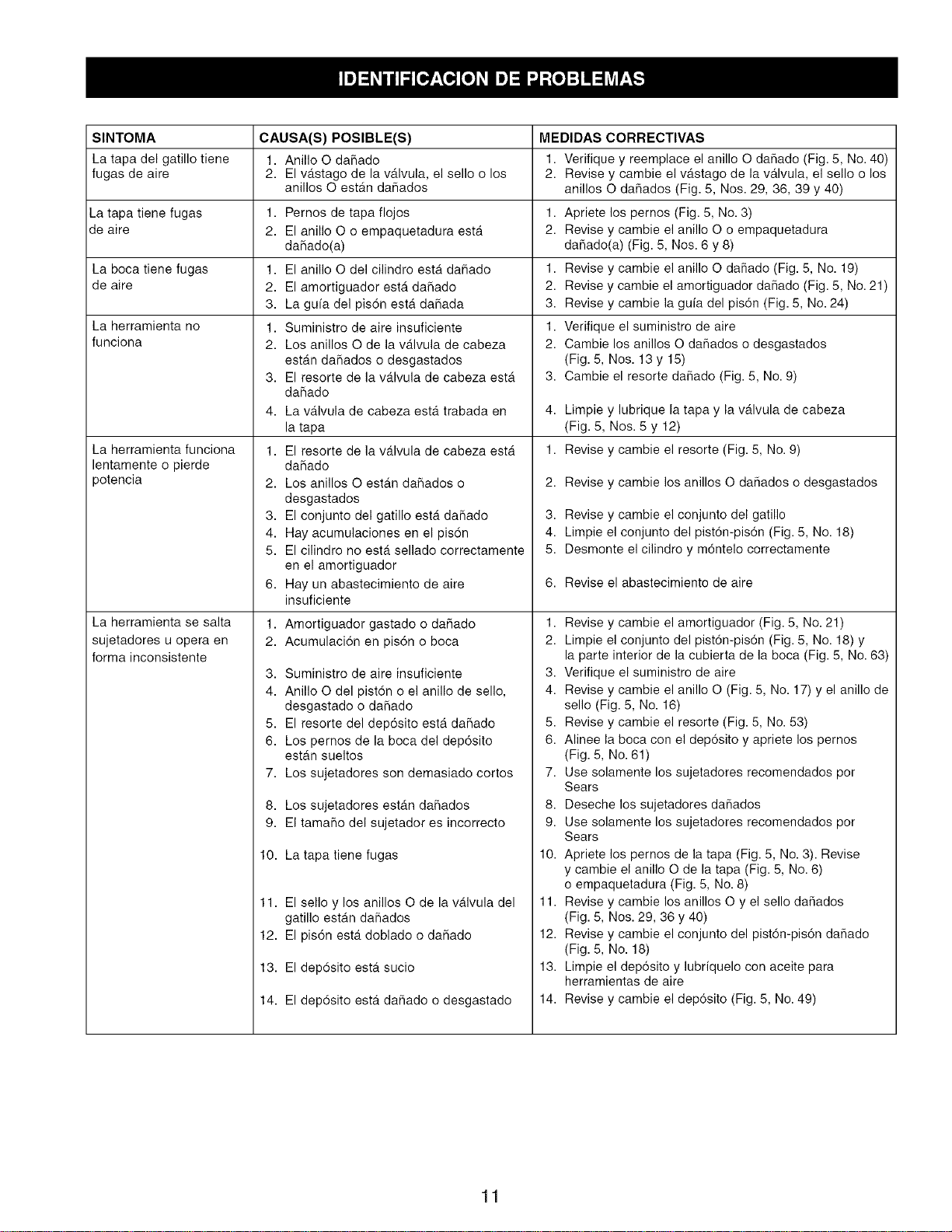
Figura 4 - Ajuste del Desviador de Escape
Presione el
Accionador
Accionador
Presionado
Figura 3 - Operacion del Disparador de Contacto
PRESION DE OPERACION
• Utilice solamente la presi6n de aire justa para la operaci6n. Si
la presi6n es superior a la requerida, la operaci6n de clavado
ser,_ ineficiente y se pueden causar dahos o el desgaste pre-
maturo de la herramienta.
,, Determine la presi6n de aire mfnima que se requiere clavan-
do algunos de los sujetadores de prueba en la pieza de tra-
bajo. Ajuste la presi6n de aire de modo que los sujetadores
de prueba se claven hasta abajo, al mismo nivel de la super-
ficie de trabajo. Si se clavan los sujetadores demasiado pro-
fundamente, se puede daffar la pieza de trabajo.
DESVIADOR DE ESCAPE
Refi@ase a las Figuras 4 y 5 (pb.ginas 10 y 6).
• El desviador del escape se puede colocar para que seffale en
cualquier direcci6n (movimiento de 360 ° completo). Vuelva a
colocar el desviador (Fig. 5, No. 2) agarrb.ndolo firmemente y
rot6.ndolo a la posici6n deseada.
Refi@ase a la Figura 5 (pagina 6).
DEPOSITO Y PISTON-PISON
• Mantenga el dep6sito y la boca de la herramienta limpios y
sin mugre, pelusas o parficulas abrasivas.
La punta del pis6n (Fig. ,5,No. 18) se puede abollar o redondear
con el tiempo.
,, Cuadre la punta del pis6n con una lima manual fina y limpia
para extender la duraci6n del pis6n y de la herramienta. El
disparo de los sujetadores ser,_ mas consistente si la punta
del pis6n se mantiene limpia y cuadrada.
MECANISMO DE SEGURIDAD
Inspeccione el mecanismo de seguridad del disparador de con-
tacto diariamente para asegurar una operaci6n correcta. No
opere la herramienta si el mecanismo no estdt operando correcta-
mente.
Ponga el interruptor de boton de presi6n rojo en el modo de dis-
paro r,_pido y siga el procedimiento siguiente para probar el
mecanismo de seguridad:
,, No toque el gatillo mientras empuja el disparador de contacto
en la pieza de trabajo. La herramienta no se debe disparar.
,, Apriete el gatillo mientras el disparador de contacto estb.
fuera del trabajo y apuntando alejdindose del operador y de
los demas. La herramienta no se debe disparar.
q, Presione y sujete el gatillo. Empuje el disparador de contacto
contra el trabajo donde se necesite un sujetador. La herra-
mienta debe clavar solamente un sujetador cada vez que el
disparador de contacto se empuja contra la pieza de trabajo.
Si el mecanismo del disparador de contacto no opera cor-
rectamente, haga reparar la herramienta inmediatamente a
trav_s del Centro de Servicios de Sears.
Repare toda pieza daffada y reemplace toda pieza faltante.
Utilice la lista de piezas para hacer el pedido de las mismas.
JUEGOS DE RECONSTRUCCION
Como pieza de repuesto hay disponibles juegos de reconstruc-
despu@s de un uso prolongado, no operan apropiadamente. Vea
la guia de bL_squeda y soluci6n de problemas para determinar
las piezas de repuesto requeridas.
Antes de reparar o ajustar la herramienta, desconectela de la
fuente de suministro de aire.
AVISO: Cuando cambie los anillos O o el cilindro, lubffquelos
con aceite para herramientas de aire antes de montarlos.
10
SINTOMA CAUSA(S) POSIBLE(S)
La tapa del gatillo tiene 1. Anillo O dahado
fugas de aire 2. El vb.stago de la v,_lvula, el sello o los
anillos O estan daffados
La tapa tiene fugas 1.
de aire 2.
La boca tiene fugas
de aire
La herramienta no
funciona
La herramienta funciona
lentamente o pierde
potencia
La herramienta se salta
sujetadores u opera en
forma inconsistente
Pemos de tapa flojos
El anillo O o empaquetadura esta
dahado(a)
1. El anillo O del cilindro esta daffado
2. El amortiguador esta da_ado
3. La gufa del pis6n esta dahada
1. Suministro de aire insuficiente
2. Los anillos O de la v,_lvula de cabeza
estan dahados o desgastados
3. El resorte de la vb.lvula de cabeza esta
dahado
4. La valvula de cabeza estb. trabada en
la tapa
1. El resorte de la vb.lvula de cabeza esta
dahado
2. Los anillos O estan da_ados o
desgastados
3. El conjunto del gatillo esta dahado
4. Hay acumulaciones en el pis6n
5. El cilindro no esta sellado correctamente
en el amortiguador
6. Hay un abastecimiento de aire
insuficiente
1. Amortiguador gastado o daffado
2. Acumulaci6n en pis6n o boca
3. Suministro de aire insuficiente
4. Anillo Odel pist6n o el anillo de sello,
desgastado o da_ado
,5. El resorte del dep6sito esta dahado
6. Los pernos de la boca del dep6sito
estan sueltos
7. Los sujetadores son demasiado cortos
8. Los sujetadores estan da_ados
9. El tamaho del sujetador es incorrecto
10. La tapa tiene fugas
11. El sello y los anillos O de la valvula del
gatillo estan dahados
12. El pis6n esta doblado o daffado
13. El dep6sito esta sucio
14. El dep6sito esta daffado o desgastado
MEDIDAS CORRECTIVAS
1. Verifique y reemplace el anillo O da_ado (Fig. 5, No. 40)
2. Revise y cambie el vastago de la valvula, el sello o los
anillos O daffados (Fig. 5, Nos. 29, 36, 39 y 40)
1. Apriete los pernos (Fig. 5, No. 3)
2. Revise y cambie el anillo O o empaquetadura
dahado(a) (Fig. 5, Nos. 6 y 8)
1. Revise y cambie el anillo O daffado (Fig. 5, No. 19)
2. Revise y cambie el amortiguador daffado (Fig. 5, No. 21)
3. Revise y cambie la guia del pis6n (Fig. 5, No. 24)
1. Verifique el suministro de aire
2. Cambie los anillos O dahados o desgastados
(Fig. 5, Nos. 13y 15)
3. Cambie el resorte daffado (Fig. 5, No. 9)
4. Limpie y lubrique la tapa y la vddvula de cabeza
(Fig. 5, Nos. 5 y 12)
1. Revise y cambie el resorte (Fig. 5, No. 9)
2. Revise y cambie los anillos O da_ados o desgastados
3. Revise y cambie el conjunto del gatillo
4. Limpie el conjunto del pist6n-pis6n (Fig. 5, No. 18)
5. Desmonte el cilindro y m6ntelo correctamente
6. Revise el abastecimiento de aire
1. Revise y cambie el amortiguador (Fig. 5, No. 21)
2. Limpie el conjunto del pist6n-pis6n (Fig. 5, No. 18) y
la parte interior de la cubierta de la boca (Fig. 5, No. 63)
3. Verifique el suministro de aire
4. Revise y cambie el anillo O (Fig. 5, No. 17) y el anillo de
sello (Fig. 5, No. 16)
5. Revise y cambie el resorte (Fig. 5, No. 53)
6. Alinee la boca con el dep6sito y apriete los pernos
(Fig. 5, No. 61)
7. Use solamente los sujetadores recomendados por
Sears
8. Deseche los sujetadores dahados
9. Use solamente los sujetadores recomendados por
Sears
10. Apriete los pernos de la tapa (Fig. 5, No. 3). Revise
y cambie el anillo O de la tapa (Fig. 5, No. 6)
o empaquetadura (Fig. 5, No. 8)
11. Revise y cambie los anillos O y el sello daffados
(Fig. ,5, Nos. 29, 36 y 40)
12. Revise y cambie el conjunto del pist6n-pis6n dahado
(Fig. 5, No. 18)
13. Limpie el dep6sito y lubriquelo con aceite para
herramientas de aire
14. Revise y cambie el dep6sito (Fig. 5, No. 49)
11
In U.S.A. or Canada
for in-home major brand repair service:
Call 24 hours a day, 7 days a week
1-800-4-MY-HOME SM(1-800-469-4663)
Para pedir servicio de reparacibn a domicilio - 1-800-676-5811
Au Canada pour tout le service - 1-877-LE-FOYER SM(1-877-533-6937)
For the repair or replacement parts you need:
Call 6 a.m. - 11 p.m. CST, 7 days a week
PartsDirect
1-800-366-PART (1-800-366-7278)
www.sears.com/partsdirect
Para ordenar piezas con entrega a domicilio - 1-800-659-7084
For the location of a Sears Service Center in your area:
Call 24 hours a day, 7 days a week
1-800-488-1222
To purchase or inquire about a Sears Maintenance Agreement:
Call 7 a.m. - 5 p.m. CST, Monday - Saturday
1-800-827-6655
SEARS
HomeCentral
II I