WHAT’S IN THE BOX
• ZonePRO Processor
• Power Cable
• RS-232 Null Modem Cable
• Rack Mount Screw Kit
DOWNLOAD THE INSTALL GUIDE
Get the install guide at http://dbxpro.com/en-US/
products/1260#documentation or scan the code to the
right with a QR scanner app on your mobile device.
WATCH THE TRAINING VIDEOS
Watch the ZonePRO training videos at http://dbxpro.
com/en-US/training or scan the code to the right with a
QR scanner app on your mobile device.
1260
Z
one
PRO
Digital Zone ProcessorDigital Zone Processor
SELECTSELECTSELECT SELECTSELECTSELECT
SELECTSELECT
Quick Start Guide
PRODUCT REGISTRATION
Register your product at http://dbxpro.com/en-US/
support/warranty_registration or scan the code to the
right with a QR scanner app on your mobile device.
ZonePRO Quick Start Guide
PN: 5059564-A
801.566.8800
dbxpro.com
© 2015 Harman. dbx Professional Products is a registered trademark of Harman. All rights reserved.
1
Download & Install ZonePRO Designer
Download and install the latest version of the ZonePRO Designer software application
from http://dbxpro.com/en-US/software.
NOTE: It is recommended that virus protection/malware software be disabled during
ZonePRO Designer installation.
2
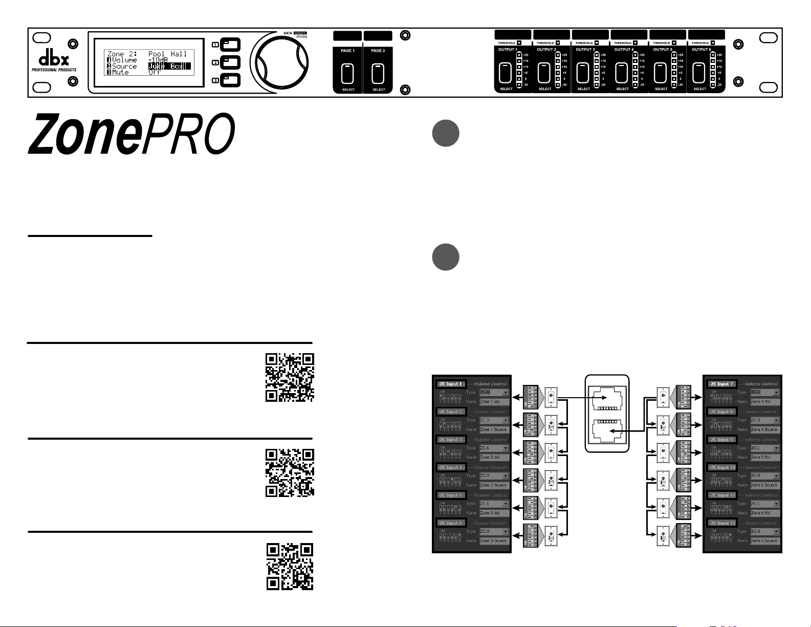
Connecting Zone Controllers
Zone Controllers (ZCs) must be connected in a daisy-chain fashion using straight-through
CAT5 cables. The below diagram shows the maximum number of 12 ZCs connected to
a ZonePRO device, how each ZC’s DIP switches would be assigned, and how the ZC ID
assignments match up with the ZonePRO Designer programming.
ZC INPUT
ZC INPUT
ID #s 1-6
(Top ZC Input Port)
ZonePRO Designer
Software Programming
DIP
Switches
ZCs
VOLUME
0
1
2
3
4
5
6
7
8
9
10
ZC-1
ZC-3
VOLUME
0
1
2
3
4
5
6
7
8
9
10
ZC-1
ZC-3
ZC-1
ZC-3
ID #s 7-12
(Bottom ZC Input Port)
ZonePRO Designer
Software Programming
DIP
Switches
ZCs
VOLUME
0
1
2
3
4
5
6
7
8
9
10
ZC-1
ZC-3
VOLUME
0
1
2
3
4
5
6
7
8
9
10
ZC-1
ZC-3
VOLUME
0
1
2
3
4
5
6
7
8
9
10
ZC-1
ZC-3
A
B
C
D
SELECT
A
B
C
D
A
B
C
D
SELECT
A
B
C
D
A
B
C
D
SELECT
A
B
C
D
ID#1
ID#2
ID#3
ID#4
ID#5
ID#6
ID #7
ID#8
ID#9
ID#10
ID#11
ID#12
A
B
C
D
SELECT
A
B
C
D
A
B
C
D
SELECT
A
B
C
D
A
B
C
D
SELECT
A
B
C
D
VOLUME
0
1
2
3
4
5
6
7
8
9
10
NOTE: If using a ZC-BOB, all CAT5 cables must be home run from each ZC to the ZC-
BOB. Daisy chaining ZCs off the ZC-BOB is not supported. A ZC must be configured as
ID #1 to be used for scene control and a ZC-FIRE must be configured as ID #2.
WHAT’S IN THE BOX
• ZonePRO Processor
• Power Cable
• RS-232 Null Modem Cable
• Rack Mount Screw Kit
DOWNLOAD THE INSTALL GUIDE
Get the install guide at http://dbxpro.com/en-US/
products/1260#documentation or scan the code to the
right with a QR scanner app on your mobile device.
WATCH THE TRAINING VIDEOS
Watch the ZonePRO training videos at http://dbxpro.
com/en-US/training or scan the code to the right with a
QR scanner app on your mobile device.
1260
Z
one
PRO
Digital Zone ProcessorDigital Zone Processor
SELECTSELECTSELECT SELECTSELECTSELECT
SELECTSELECT
Quick Start Guide
PRODUCT REGISTRATION
Register your product at http://dbxpro.com/en-US/
support/warranty_registration or scan the code to the
right with a QR scanner app on your mobile device.
ZonePRO Quick Start Guide
PN: 5059564-A
801.566.8800
dbxpro.com
© 2015 Harman. dbx Professional Products is a registered trademark of Harman. All rights reserved.
1
Download & Install ZonePRO Designer
Download and install the latest version of the ZonePRO Designer software application
from http://dbxpro.com/en-US/software.
NOTE: It is recommended that virus protection/malware software be disabled during
ZonePRO Designer installation.
2
Connecting Zone Controllers
Zone Controllers (ZCs) must be connected in a daisy-chain fashion using straight-through
CAT5 cables. The below diagram shows the maximum number of 12 ZCs connected to
a ZonePRO device, how each ZC’s DIP switches would be assigned, and how the ZC ID
assignments match up with the ZonePRO Designer programming.
ZC INPUT
ZC INPUT
ID #s 1-6
(Top ZC Input Port)
ZonePRO Designer
Software Programming
DIP
Switches
ZCs
VOLUME
0
1
2
3
4
5
6
7
8
9
10
ZC-1
ZC-3
VOLUME
0
1
2
3
4
5
6
7
8
9
10
ZC-1
ZC-3
ZC-1
ZC-3
ID #s 7-12
(Bottom ZC Input Port)
ZonePRO Designer
Software Programming
DIP
Switches
ZCs
VOLUME
0
1
2
3
4
5
6
7
8
9
10
ZC-1
ZC-3
VOLUME
0
1
2
3
4
5
6
7
8
9
10
ZC-1
ZC-3
VOLUME
0
1
2
3
4
5
6
7
8
9
10
ZC-1
ZC-3
A
B
C
D
SELECT
A
B
C
D
A
B
C
D
SELECT
A
B
C
D
A
B
C
D
SELECT
A
B
C
D
ID#1
ID#2
ID#3
ID#4
ID#5
ID#6
ID #7
ID#8
ID#9
ID#10
ID#11
ID#12
A
B
C
D
SELECT
A
B
C
D
A
B
C
D
SELECT
A
B
C
D
A
B
C
D
SELECT
A
B
C
D
VOLUME
0
1
2
3
4
5
6
7
8
9
10
NOTE: If using a ZC-BOB, all CAT5 cables must be home run from each ZC to the ZC-
BOB. Daisy chaining ZCs off the ZC-BOB is not supported. A ZC must be configured as
ID #1 to be used for scene control and a ZC-FIRE must be configured as ID #2.
3
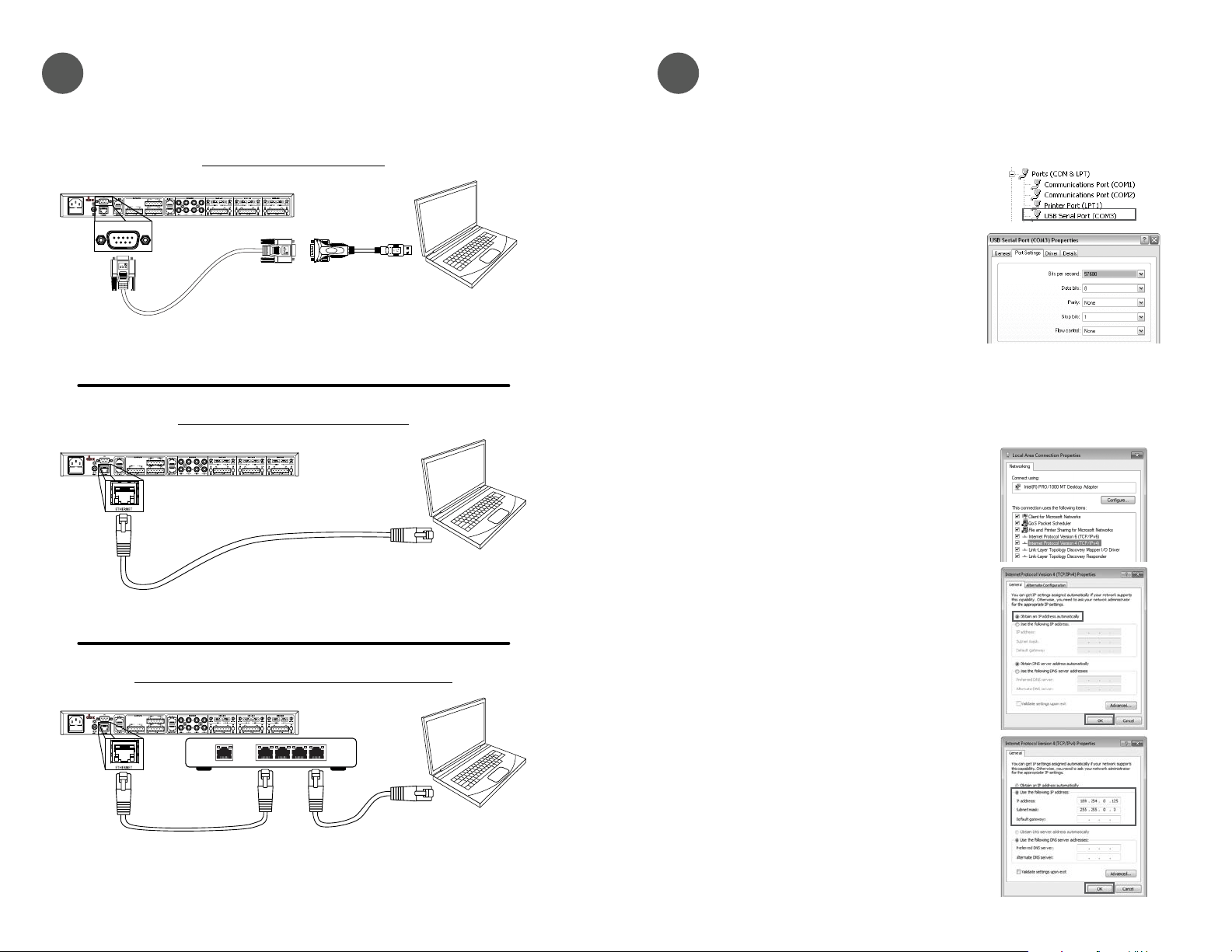
Connecting to a ZonePRO Device
Connect your computer to the ZonePRO device using either the included RS-232 Null
Modem cable or via Ethernet as shown in the below diagrams.
Ethernet Direct Computer Connection
ZonePRO
Crossover Ethernet Cable
Computer
w/ Ethernet Port
(Must be a crossover Ethernet cable,
a straight-through Ethernet cable will not work)
Ethernet Computer Connection w/ Switch or Router
Computer
w/ Ethernet Port
ZonePRO
Straight-Through Ethernet Cables
Network Switch
or Router
WAN LAN
1 2 3 4
RS-232 Computer Connection
PC
ZonePRO
RS-232 to USB
Serial Adapter
(Required if computer
doesn’t have a serial port)
Computer
w/ RS-232 or USB Port
dbx RS-232 Null
Modem Cable
Diagram A
Diagram B
Diagram C
4
Going Online with a ZonePRO Device
You can connect to a ZonePRO device (referred to as going “online”) then program it in
real time or load a pre-programmed file into the device. To go online with a ZonePRO
device follow these steps:
A. To Connect via Serial
Go to Windows Device Manager > Ports
(COM & LPT) and double-left-click on the
COM port you wish to use for connecting to the
ZonePRO.
Make sure the serial port settings are set as
shown in the screenshot to the right.
NOTE: Not all USB to Serial Adapters will work
with the ZonePRO devices. Please visit dbxpro.
com for additional information on compatible
USB to Serial adaptors.
Go to step C.
To Connect via Ethernet
In order to initially connect to a ZonePRO
device via Ethernet, the computer must have
an IP address that conforms to the Automatic
Private IP Addressing standard (i.e., IP:
169.254.X.X, subnet mask: 255.255.0.0).
Go to Windows Start Menu > Control Panel
> Network and Internet > Networking and
Sharing Center > Local Area Connection
> Properties. Double-left-click the “Internet
Protocol Version 4” option.
If connecting directly to the computer (as
shown in Diagram B to the left), take note of
your current settings and set your computer’s
network interface card to obtain an IP address
automatically then click the OK button.
If connecting via a router or switch with DHCP
enabled (as shown in Diagram C to the left),
take note of your current settings and set the
computer’s network interface card with a static
IP address, such as the one shown to the right,
then click the OK button.
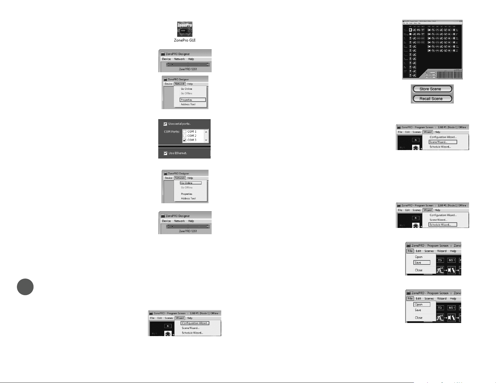
B. Launch the ZonePRO Designer application.
C. A ZonePRO icon should automatically appear
in the main window if a connection to the
ZonePRO device is established. Double-left-
click the ZonePRO icon to open the Program
Screen window then go to step 5.
If the ZonePRO Device icon did not
automatically appear, go to Network >
Properties.
If connecting via serial, ensure the “Use serial
ports” box is checked and that the COM port
number identified in step A is checked then
click the Finish button.
If connecting via Ethernet, uncheck the “Use
serial ports” box and ensure the “Use Ethernet”
box is checked then click the Finish button.
Select Network > Go Online.
The ZonePRO icon should appear in the main
window. Double-left-click the icon to open the
Program Screen window then go to step 5.
If a connection to the ZonePRO device still
can’t be established, please refer to the
ZonePRO Install Guide.
5
Programming a ZonePRO
A. From the Program Screen window, go to
Wizard > Configuration Wizard.
Follow the on-screen instructions to program
the ZonePRO device.
When done, click the Finish button
B. Double-left-click any blocks in the Program
Screen window to edit ZonePRO audio
processing settings.
C. Store the programmed scene by clicking the
Store Scene button, selecting the scene
location, naming the scene, then clicking the
OK button.
D. If scene recalls requiring Zone Controller
assignment changes are required for the
application, such as when combining rooms,
select Wizard > Scene Wizard.
Follow the on-screen instructions then click the
Finish button.
Repeat steps B-D until all scenes required for
the application have been created.
E. If required for the application, select Wizard
> Schedule Wizard to schedule automatic
ZonePRO scene changes.
F. To save the program file to your computer’s
hard drive for backup or for loading into a
ZonePRO device at a later time, select File >
Save from the Program Screen window.
G. To load a program file into a ZonePRO device,
select File > Open from the Program Screen
window then select the ZPD file from your
computer’s hard drive.
Thanks for choosing dbx.
3
Connecting to a ZonePRO Device
Connect your computer to the ZonePRO device using either the included RS-232 Null
Modem cable or via Ethernet as shown in the below diagrams.
Ethernet Direct Computer Connection
ZonePRO
Crossover Ethernet Cable
Computer
w/ Ethernet Port
(Must be a crossover Ethernet cable,
a straight-through Ethernet cable will not work)
Ethernet Computer Connection w/ Switch or Router
Computer
w/ Ethernet Port
ZonePRO
Straight-Through Ethernet Cables
Network Switch
or Router
WAN LAN
1 2 3 4
RS-232 Computer Connection
PC
ZonePRO
RS-232 to USB
Serial Adapter
(Required if computer
doesn’t have a serial port)
Computer
w/ RS-232 or USB Port
dbx RS-232 Null
Modem Cable
Diagram A
Diagram B
Diagram C
4
Going Online with a ZonePRO Device
You can connect to a ZonePRO device (referred to as going “online”) then program it in
real time or load a pre-programmed file into the device. To go online with a ZonePRO
device follow these steps:
A. To Connect via Serial
Go to Windows Device Manager > Ports
(COM & LPT) and double-left-click on the
COM port you wish to use for connecting to the
ZonePRO.
Make sure the serial port settings are set as
shown in the screenshot to the right.
NOTE: Not all USB to Serial Adapters will work
with the ZonePRO devices. Please visit dbxpro.
com for additional information on compatible
USB to Serial adaptors.
Go to step C.
To Connect via Ethernet
In order to initially connect to a ZonePRO
device via Ethernet, the computer must have
an IP address that conforms to the Automatic
Private IP Addressing standard (i.e., IP:
169.254.X.X, subnet mask: 255.255.0.0).
Go to Windows Start Menu > Control Panel
> Network and Internet > Networking and
Sharing Center > Local Area Connection
> Properties. Double-left-click the “Internet
Protocol Version 4” option.
If connecting directly to the computer (as
shown in Diagram B to the left), take note of
your current settings and set your computer’s
network interface card to obtain an IP address
automatically then click the OK button.
If connecting via a router or switch with DHCP
enabled (as shown in Diagram C to the left),
take note of your current settings and set the
computer’s network interface card with a static
IP address, such as the one shown to the right,
then click the OK button.
B. Launch the ZonePRO Designer application.
C. A ZonePRO icon should automatically appear
in the main window if a connection to the
ZonePRO device is established. Double-left-
click the ZonePRO icon to open the Program
Screen window then go to step 5.
If the ZonePRO Device icon did not
automatically appear, go to Network >
Properties.
If connecting via serial, ensure the “Use serial
ports” box is checked and that the COM port
number identified in step A is checked then
click the Finish button.
If connecting via Ethernet, uncheck the “Use
serial ports” box and ensure the “Use Ethernet”
box is checked then click the Finish button.
Select Network > Go Online.
The ZonePRO icon should appear in the main
window. Double-left-click the icon to open the
Program Screen window then go to step 5.
If a connection to the ZonePRO device still
can’t be established, please refer to the
ZonePRO Install Guide.
5
Programming a ZonePRO
A. From the Program Screen window, go to
Wizard > Configuration Wizard.
Follow the on-screen instructions to program
the ZonePRO device.
When done, click the Finish button
B. Double-left-click any blocks in the Program
Screen window to edit ZonePRO audio
processing settings.
C. Store the programmed scene by clicking the
Store Scene button, selecting the scene
location, naming the scene, then clicking the
OK button.
D. If scene recalls requiring Zone Controller
assignment changes are required for the
application, such as when combining rooms,
select Wizard > Scene Wizard.
Follow the on-screen instructions then click the
Finish button.
Repeat steps B-D until all scenes required for
the application have been created.
E. If required for the application, select Wizard
> Schedule Wizard to schedule automatic
ZonePRO scene changes.
F. To save the program file to your computer’s
hard drive for backup or for loading into a
ZonePRO device at a later time, select File >
Save from the Program Screen window.
G. To load a program file into a ZonePRO device,
select File > Open from the Program Screen
window then select the ZPD file from your
computer’s hard drive.
Thanks for choosing dbx.