Loading ...
Loading ...
Loading ...
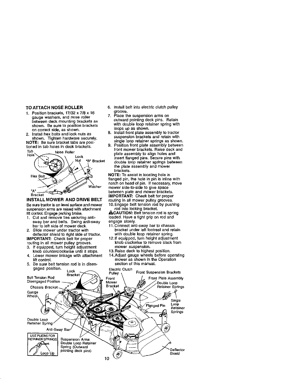
TO ATrACH NOSE ROLLER
1. Position brackets, 17/32 x 7/8 x 16
gauge washers, and nose roller
between deck mounting brackets as
shown. Be sure to position brackets
on correct side, as shown.
2. Install hex bolts and lock nuts as
shown. Tighten hardware securely.
NOTE: Be sure bracket tabs are posi-
tioned in tab holes in deck brackets.
Tab Nose Roller
Lock
•B" Bracket
Hex Bolt
Bracket
INSTALL MOWER AND DRIVE BELT
Be suretractoris onlevelsurfaceand mower
suspensionarmsare raisedwi_ attachment
liftcontrol.Engageparking brake.
1. Cut and remove ties securing anti-
sway bar and belts. Swing anti-sway
barto left side of mower deck.
2. Slide mower under tractorwith
deflectorshield to dght side of tractor.
IMPORTANT: Check belt for proper
routing in aUmower pulley grooves.
3. If equipped, turn height adjustment
knob counterclockwise until it stops.
4. Lower mower linkage with attachment
lift control.
5. Be sure belt tension rod is in disen-
gaged position. Lock
Belt TensionRod
Disengaged Position .-_,'J
Chassis
Gauge
Wheel
Double Loop
Retainer Spring
Anti-Sway
USEPUERSFOR I
RETAINERSPRINGSI Suspension Arms
/_Loop Double Loop Retainer
Spring (Outward
Up pointing deck pins)
6. Install belt into electdcclutch pulley
groove.
7. Place the suspension arms on
outward pointingdeck pins. Retain
with double loop retainer spring with
loops up as shown.
8. Installfront plate assembly1otractor
suspension brackets and retain with
single loop retainer springsas shown.
9. Positionfront plate assemb]y between
front mower brackets. Raise deck and
plate assembly to align holes and
insert flanged pins. Secure pins with
double loop retainer springs between
the plate assembly and mower
brackets.
NOTE: To assist in locatinghole in
flanged pin, the hole in pin is inlinewith
notch onhead ofpin. If necessary,move
mower side-to-sideto give space
between plate and mower brackets.
IMPORTANT: Check belt for proper
routing in all mower pulley grooves.
10.Engage belt tension rod by pushing
rod into locking bracket.
•qLCAUTION: Belt tension rodis spring
loaded. Have a tight grip on red and
engage slowly.
11.Connect anti-sway bar to chassis
bracket under leftfootrest and retain
with double loop retainer spring.
12.1f equipped, turn height adjustment
knob clockwiseto remove slack from
mower suspension.
13. Raise deck to highest position.
14.Adjust gauge wheels before operating
mower as shown in the Operation
section of this manual.
Electric Clutch
Pulley Front Suspension Brackets
Front Front Plate Assembly
Mower _Double Loop
Bracket Retainer Springs
Single
Loop
Retainer
Springs
10
Shield
Loading ...
Loading ...
Loading ...