Read all instructions before you
operate
your grill.
Save these instructions!
To installer or person assembling grill:
Leave this manual
with grill for future reference.
To consumer:
Keep this manual for future reference.
www.sunstonemetalproducts.com
ITEM NO. SUNCHSZ30
CERTIFIED

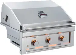
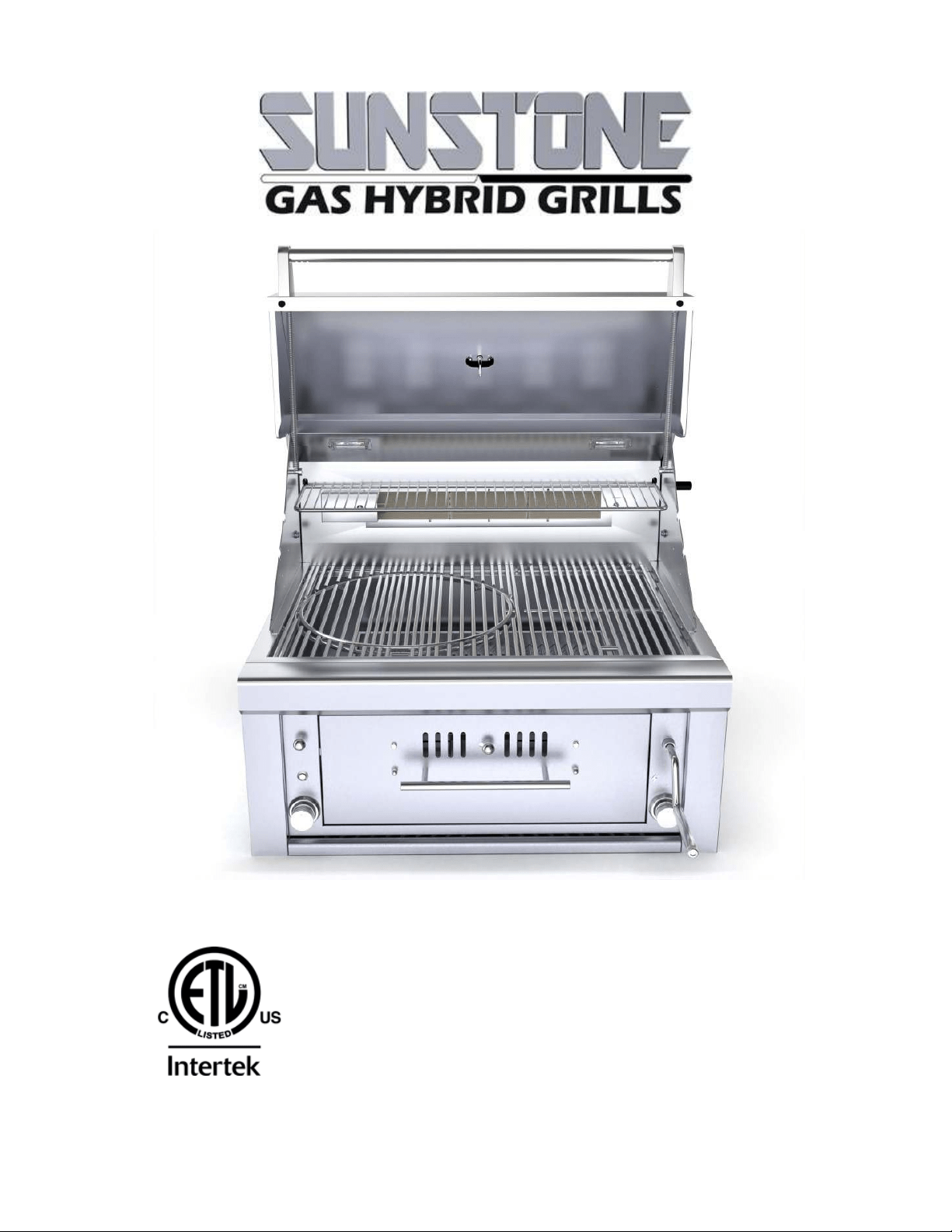
Welcome & Congratulations
Congratulations on your purchase of a new Sunstone Gas Hybrid Charcoal Wood Burning Grill! We are very
proud of our product and we are completely committed to providing you with the best service possible.
Your satisfaction is our #1 priority. Please read this manual carefully to understand all the instructions
about how to install, operate and maintain for optimum performance and longevity. We know you’ll enjoy
your new grill and thank you for choosing our product. We hope you consider us for future purchases.
How to Obtain Service
Before you call
Is there Gas supplied to the Grill?
Have you recently refilled the LP Tank?
Please make sure you have the following information:
MODEL NUMBER | DATE OF PURCHASE| INVOICE NUMBER.
For warranty service, contact SUNSTONE Customer Service Department at (888)-934-9449 or email
service@sunstonemetalproducts.com.
Must keep copy of your sales slip for proof of purchase.
NAME_________________________________ DATE OF PURCHASE _______________________
ADDRESS_______________________________________________________________________________
MODEL NO_____________________________INVOICE NO_______________________________________
COMPANY THAT YOU PURCHASED FROM
________________________________________________
SUNSTONE METAL PRODUCTS LLC.
16004 Central Commerce Dr, Pflugerville Texas 78660.
Business Hours.
Mon. to Thur. 9:00AM to 4:30PM
Closed Fri/Sat/Sun
Tel: 512-487-5116
Toll Free: 888-934-9449 (Technical Support Line)
Fax: 512-487-7016
INDEX DIRECTORY
ATTENTION: Indicates a potentially hazardous
situation which, if not avoided, may result in minor or
moderate personal injury, or property damage.
WARNING:
Indicates an imminently hazardous
situation which, if not avoided, will result in death or
serious injury.
VOLTAGE:
Indicates a potentially hazardous
situation which, if not avoided, may result in minor or
moderate electrical shock.
EXPLOSION:
Indicates an imminently hazardous
situation which, if not avoided, will result in possible
explosion and cause death or severe injury.
BODILY INJURY:
Indicates a potentially hazardous
situation which, if not avoided, may result in minor or
moderate personal injury, or property damage.
HOT SURFACE:
Indicates an imminently hazardous
hot
surface which, if not avoided, will result in
serious
burn or injury.
LIVE CIRCUIT:
Indicates a potentially hazard from
Live electrical current that if extreme caution is not
used, may result in minor or moderate personal injury,
or property damage.
HAZARDS & WARNING SIGNS
START-UP
CHECKLIST
“FIRST TIME STARTUP CHECKLIST”
Transformer Electrical Plug is properly installed.
Installation of the proper gas type and regulator settings.
The proper Regulator & Gas Connection is complete.
Minimum 24” Inch to Combustible Clearances are maintained.
All packaging has been removed from Interior of Grill
All parts and components are properly installed.
An installer-supplied manual gas shut-off valve is fully accessible.
LP hose is clean and inspected for cuts, wear, abrasion, or leaks.
Replace if necessary, with a suitable UL, ETL or CSA Listed part with
internally threaded connection.
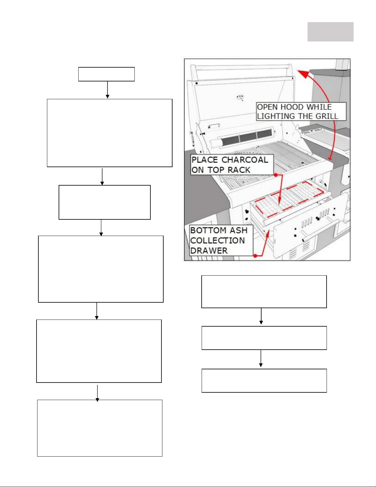
EXPLOSION: When Igniting the Grill – Always keep
the Hood Open.
ATTENTION: Never operate the grill unattended.
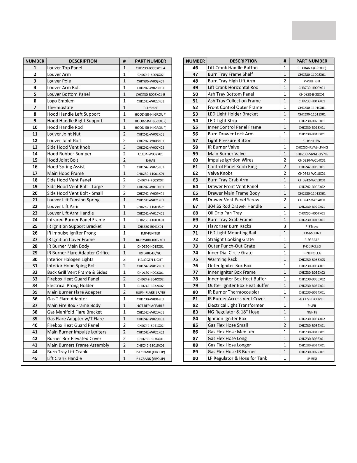
GRILL
PARTS
–
PARTS INDEX
PAGE 1
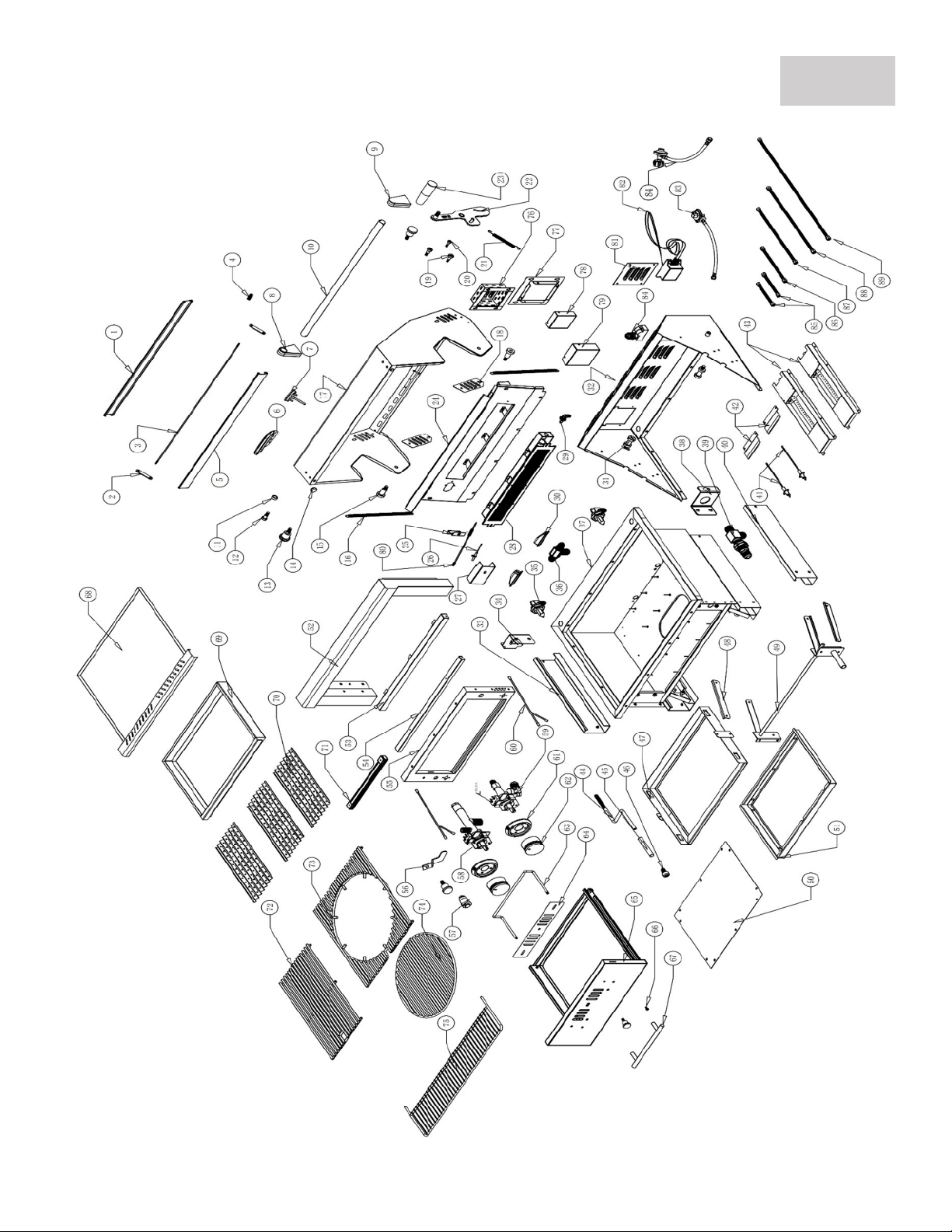
GRILL PARTS
–
PARTS DIAGRAM
PAGE 2
LIVE CIRCUIT
: Use only with a Ground-Fault Circuit Interrupter - GFCI protected Outlet
with this grill.
VOLTAGE
: Use only extension cords approved for outdoor use marked with W-A and
rated for the power of this appliance.
GRILL
INSTALLATION
–
STEP BY STEP GUIDE
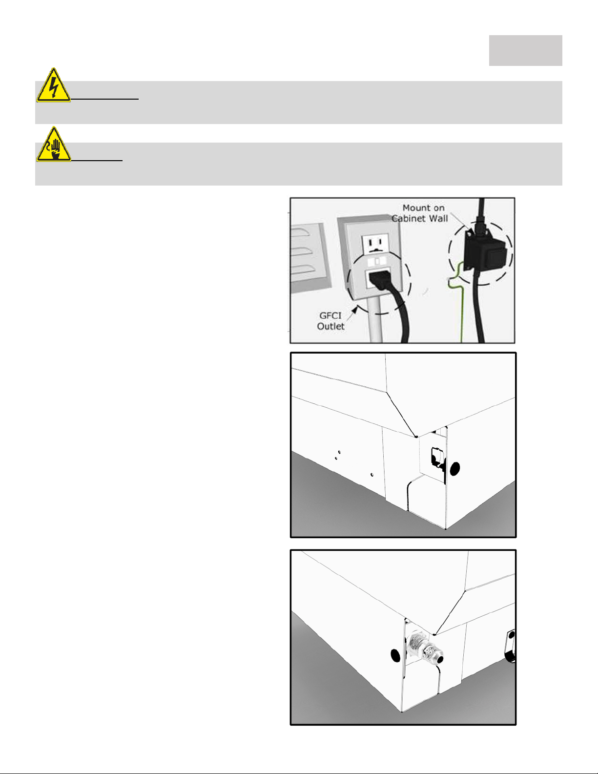
1. Mount Transformer
Using metal screws and attach the
transformer to the back inner wall of your
island’s cabinet wall, somewhere near the
already installed GFCI electrical outlet.
When you plug the transformer in, double
check the GFCI breaker switch, that the
outlet has power.
2
. Elect. Connection
Locate the Light Button on Left side of grill
control panel. The Transformer's electrical
connection to grill is located behind control
panel, next to light button. The connection
clips together to form a secure connection.
Double check that all wires are tightly
pushed into plug sockets, so all wires make
proper connections. You can tuck wire into
body of grill or island frame.
PAGE 3
3. Gas Line Connection
See the BACK-RIGHT UNDER-SIDE – This is
where the Gas Line will connect to the Grill.
Grill is shipped as Liquid Propane ONLY and
includes a LP-Regulator for portable tank.
Recommendation to have an 18” hose to
allow grill to be pulled out if necessary. For
LP & NG Gas Installation, see page 10 thru 13
for complete instructions or call 888-934-
9449 for assistance.
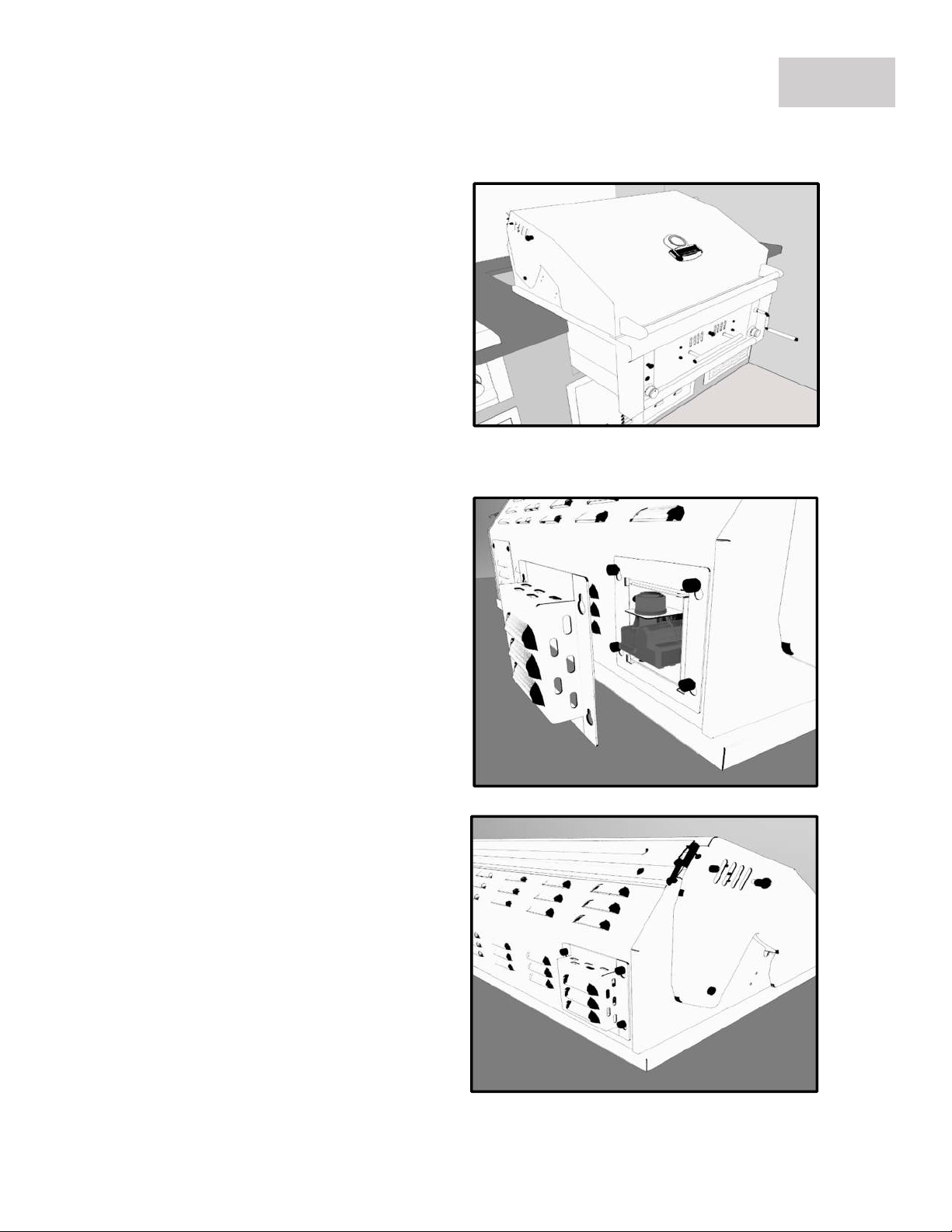
5. Install the Battery
The back left side of grill, find the vented
box extruding out. This box can be
unhinged by lifting upwards and off
revealing the black igniter box within.
Next unscrew the black cap which will
release the igniter box from the hole
mount. Now you can place an AA Battery
in the open port, with the Male Side
facing out.
GRILL
INSTALLATION
–
STEP BY STEP GUIDE
PAGE 4
6
. Allow for Ventilation
The grill is engineered with special vents
on the back of unit, which allow proper
airflow out of the back of grill. Be sure to
allow a minimum of 6" behind grill for
proper air ventilation and to allow hood
to open properly. Push grill all the way
into cut-out, so there are no gaps
present to inside of island frame and grill
control panel is flush against island wall.
4. Slide Grill in Place
The grill is specially designed with an
internal built in hanger lip located at the
Right, Left and Back sides. The grill lip
allows it to hang by the three supported
edges on the right, left and back. The
front control panel requires no
supporting edge, it is designed to hang
down the front of your cut-out.
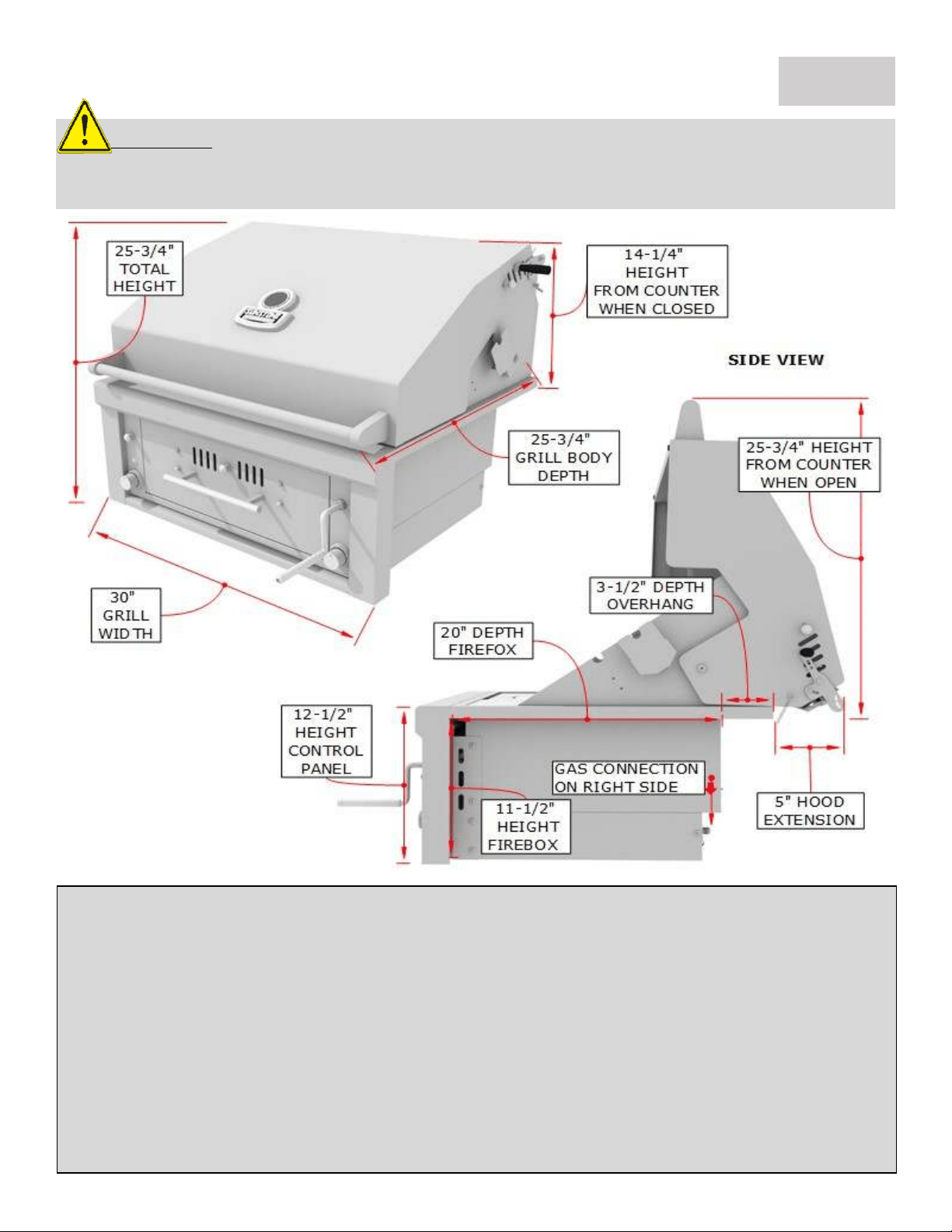
Product Size
Overall Width-------------------- 30"
Overall Height------------------- 25-3/4"
Overall Depth-------------------- 25-3/4"
Control Panel Height----------- 12-1/2”
Hood Closed -------------------- 14-1/4”
Firebox Size
Box Width (Not Shown)------ 26"
Box Height---------------------- 11-1/2"
Box Depth----------------------- 20"
Control Panel Height----------- 12-1/2”
GRILL
INSTALLATION
–
PRODUCT DETAILS
PAGE 5
Technical Measurements – See measurement box next page
If the cut-out is smaller than what ours is shown, or you are installing grill into cabinet structure you may
need to refer to these engineer dimensions specifically the grill firebox dimensions. See next page for
Dimension Table. (Measurements were obtained from engineer drawing, margin of error is within 1/8” to
actual product)
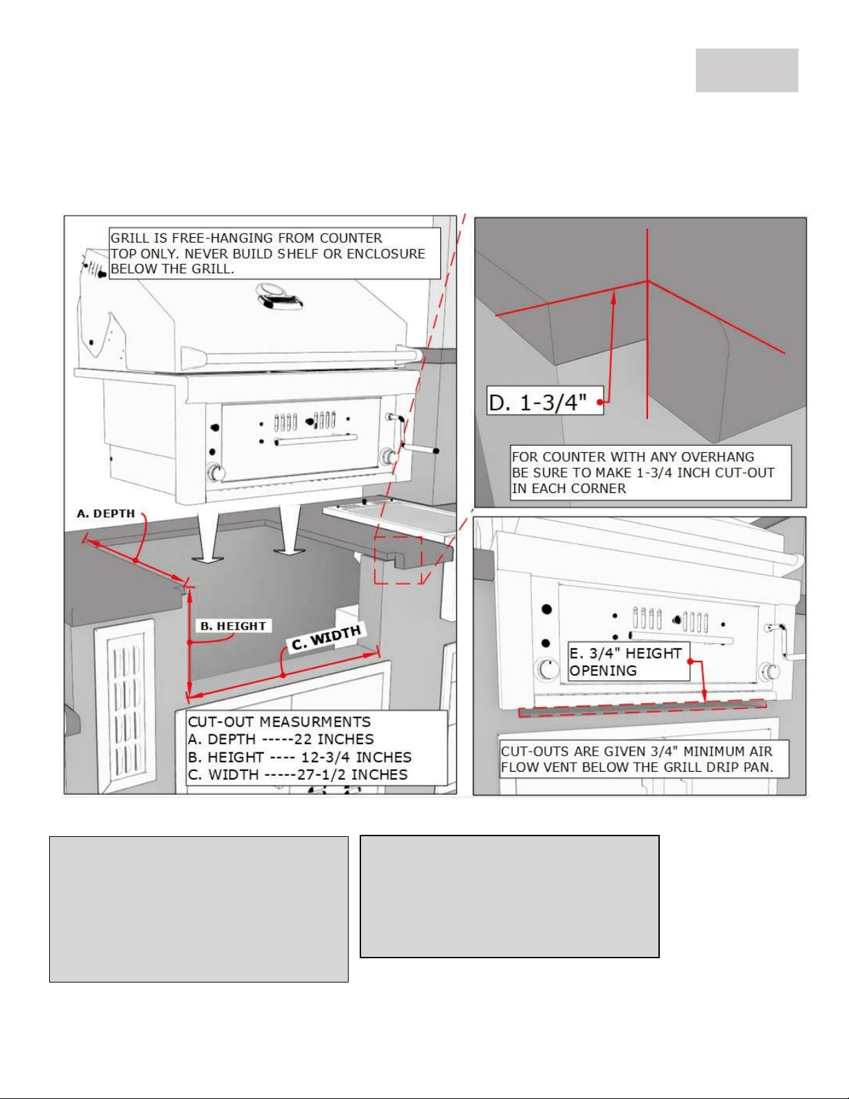
ATTENTION
: Never build an enclosure under the Grill or partition side walls, the Grill
must be Free Hanging supported by the countertop only! Must have clear access to
underside of Grill within reach of at least Two Vents.
GRILL
INSTALLATION
–
CUT
-
OUT DETAILS
PAGE 6
1.
Countertop Slide
-
in Installation
(A) Grill Cut-out Depth ------------------------------------------------------------------ 22” Depth
(B) Grill Cut-out Height (Allow ¾” Air-Flow Gap Below Drip Pan) ------------ 12-3/4” Height
(C) Grill Cut-out Width------------------------------------------------------------------- 27-1/2” Width
(D) Make 1-3/4”W x1”D Notch Cut-Out on both sides of cut-out counter edge, to allow grill to slide
flush against the island finish wall.
(E) Leave Minimum ¾” Gap below Drip Pan for Air/Gas Ventilation
Must have TWO Vents in HIGH position for Natural Gas
Must have TWO Vents in LOW position for Liquid Propane
Properly stow-away the Liquid Propane Tank
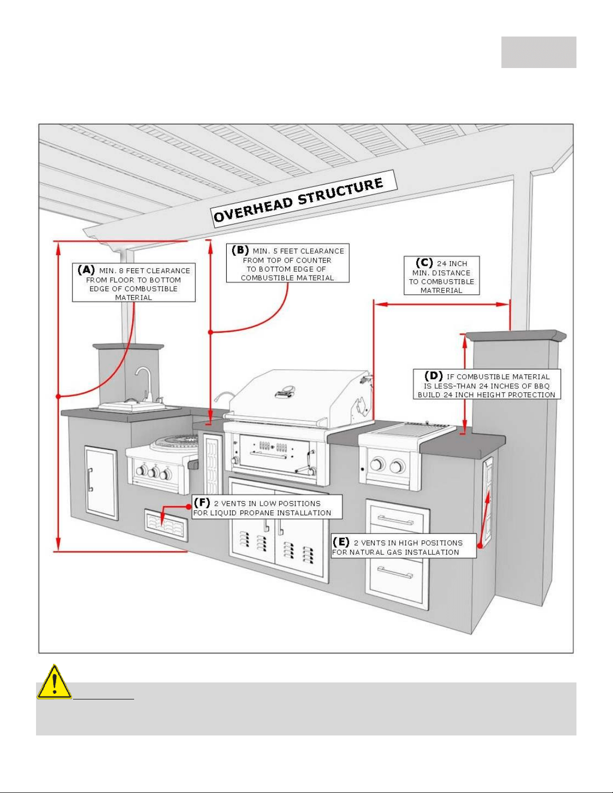
GRILL INSTALLATION – OVERHEAD STRUCTURE
Overhead Structure Definition:
Structure built above Appliance that is sometimes attached to the home’s exterior outside wall or
roof and there is a Minimum of “Two” adjacent sides which are open with outside exposure.
PAGE 7
ATTENTION:
All Gas Grill Installations MUST HAVE MINIMUM TWO AIR-FLOW VENTS, either in
ELEVATED POSITION for Natural Gas or LOWERED POSITION for Liquid Propane. Your Warranty may be
VOID if island does not meet basic setup requirements.
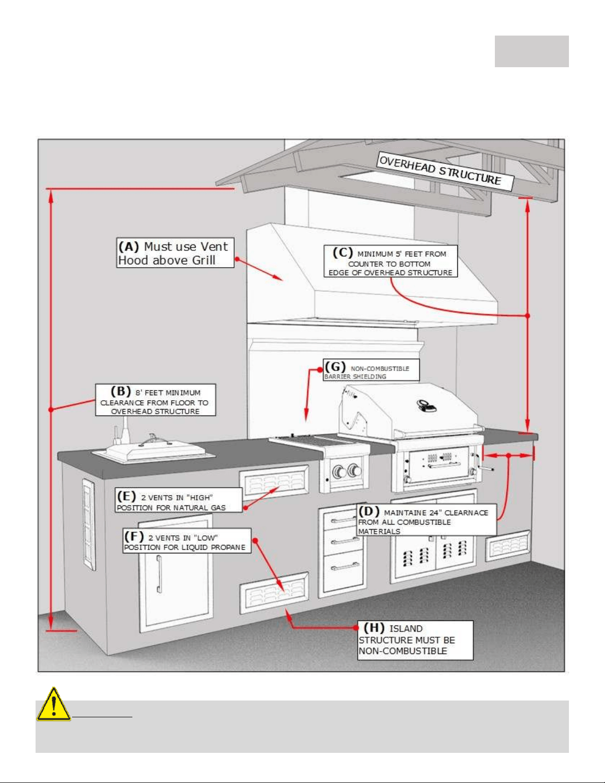
Minimum Distances to Combustible Materials or other
Appliance ONLY, Non-Combustible materials do not apply!
(A) Must use vent hood above grill for enclosed structures
(B) Minimum clearance from floor to overhead structure 8’ Min. Clearance
(C) Minimum distance from counter to overhead structure 5’ Min. Clearance
(D) Minimum clearance from all combustible materials 24” Min. Clearance
(E) Must have TWO Vents in HIGH position for Natural Gas
(F) Must have TWO Vents in LOW position for Liquid Propane
(G) Install Non-Combustible Barrier Shielding, Stainless Steel Sheet is recommended.
(H) Island Structure must be Non-Combustible otherwise must use grill jacket or metal cabinet.
BODILY INJURY: Failure to maintain required clearances create a fire hazard that
may result in property damage or serious personal injury.
Clearances to Combustible Construction:
Minimum of 24” from the sides and rear of grill must be maintained to adjacent vertical combustible
construction above the countertop level. You should take in account that there is a large volume of heat,
and smoke will exhaust from the rear of the grill. This may discolor or damage unprotected areas, do not
install under unprotected combustible construction without using a fire safe ventilation system. A 24”
minimum clearance must be maintained under the countertop to combustible construction. The clearance
can be modified by a use of an insulated jacket.
DEFINITION OF COMBUSTIBLE MATERIAL -
Any
materials of a building structure or decorative structure
made of wood, compressed paper, plant fibers, vinyl/plastic or other materials that are capable of transferring heat
or being ignited and burned. Such material shall be considered combustible even though flame-proofed, fire-
retardant treated or surface-painted, or plastered.
GRILL INSTALLATION
–
ENCLOSED INSTALLATION
Minimum Distances to Combustible Materials or other
Appliance ONLY, Non-Combustible materials do not apply!
(A) From Floor to Overhead Combustible Structure 8’ Min. Clearance
(B) From Counter to Overhead Combustible Structure 5’ Min. Clearance
(C) From Appliance to Combustible Material 24” Min. Width Clearance
(D) From Counter to Combustible Material if within 24” of Appliance
24
" Min.
Height
Clearance
(E) Must have TWO Vents in HIGH position for Natural Gas
(F) Must have TWO Vents in LOW position for Liquid Propane
PAGE 8
The Tab
le below refers to illustration on page 7
The Table below refers to illustration on page 9
ATTENTION:
All Gas Grill Installations MUST HAVE MINIMUM TWO AIR-FLOW VENTS, either in
ELEVATED POSITION for Natural Gas or LOWERED POSITION for Liquid Propane. Your Warranty may be
VOID if island does not meet basic setup requirements.
GRILL INSTALLATION
–
ENCLOSED INSTALLATION
PAGE 9
Enclosed Installation Definition:
Structure built above Appliance that is attached to the home’s exterior outside wall, roof or is inside a
separate structure like outdoor room and there is a Minimum of “One” Side open with outside exposure.
GAS SETUP
–
INSTALLATION OVERVIEW
PAGE 10
CAUTION:
Gas conversion kits are available from Customer care by dialing 888-934-9449.
When ordering gas conversion kits, have the model number, and the type of gas (natural or LP) ready.
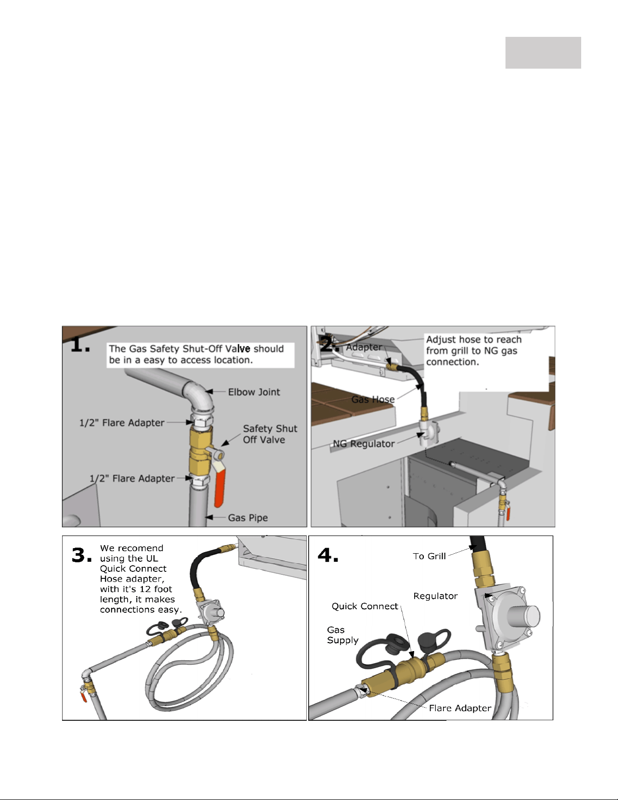
Use only the gas pressure regulator supplied with this appliance. This
regulator is set for an outlet pressure of 11 inches water column.
An installer-supplied gas shut-off valve must be installed in an easily
accessible location.
All pipe sealants must be an approved type and resistant to the
actions of LP/NG Gas.
Never use pipe sealant on flare fittings.
All gas connections should be made by a qualified technician and in
accordance with local codes and ordinances.
Before connecting grill to gas source, make sure BBQ Grill control
knobs are in “OFF” position.
Verify the type of gas supply to be used, either Natural Gas or Liquid
Propane, and make sure the marking on the appliance rating label
agrees with that of the supply.
The installation of this appliance must conform with local codes or, in the
absence of local codes, with either National Fuel Gas Code, ANSI Z223.1/ NFPA
54, Natural Gas and Propane Installation Code, CSA B149.1, or Propane Storage
and Handling Code, B149.2, or the Standard for Recreational Vehicles, ANSI A
119.2/ NFPA 1192M, and CSA Z240 RV Series, Recreational Vehicle Code, as
applicable.
ATTENTION:
Always take a leak test before lighting the grill to prevent a possible fire or explosion.
Never store a spare propane cylinder in the vicinity of this Grill, or in the vicinity of any other potential heat
source. Never attempt to attach this grill
to the self-contained LP gas system. Do not use grill until leak
testing.
GAS SETUP
–
LARGE CAPACITY LP TANKS
PAGE 11
ATTENTION:
If you have a Side Yard Propane Tank, you MUST have additional Medium
Pressure Regulator located at the Grill. If you do not serious bodily harm may result or damage to
the grill and island structure from HIGH Heat.
For this type of installation, it is most like NG gas installation method, only the
regulator is set for liquid propane. First you will install a gas pipe, coming into island
from outside, be sure the Safety Shut-Off valve is easily accessible.
Next, locate the gas manifold on grill, for this type of installation, the LP Regulator
Hose that comes with your LP Burner is not needed. Gas connections are made with
all 3/8" flare Compression Adapters, and UL Gas Hoses.
A LP REGULATOR is required for this type of installation, even if the LP Tank is
installed with one already. LP regulator for grill should be set for a minimum of
120,000 BTU's with Medium Pressure. This LP grill does not come with an
independent LP regulator for this type of installation. Contact the company you
purchased from, or your local plumber to locate one, that is made for commercial
style grills.
Large Capacity
LP
Tanks
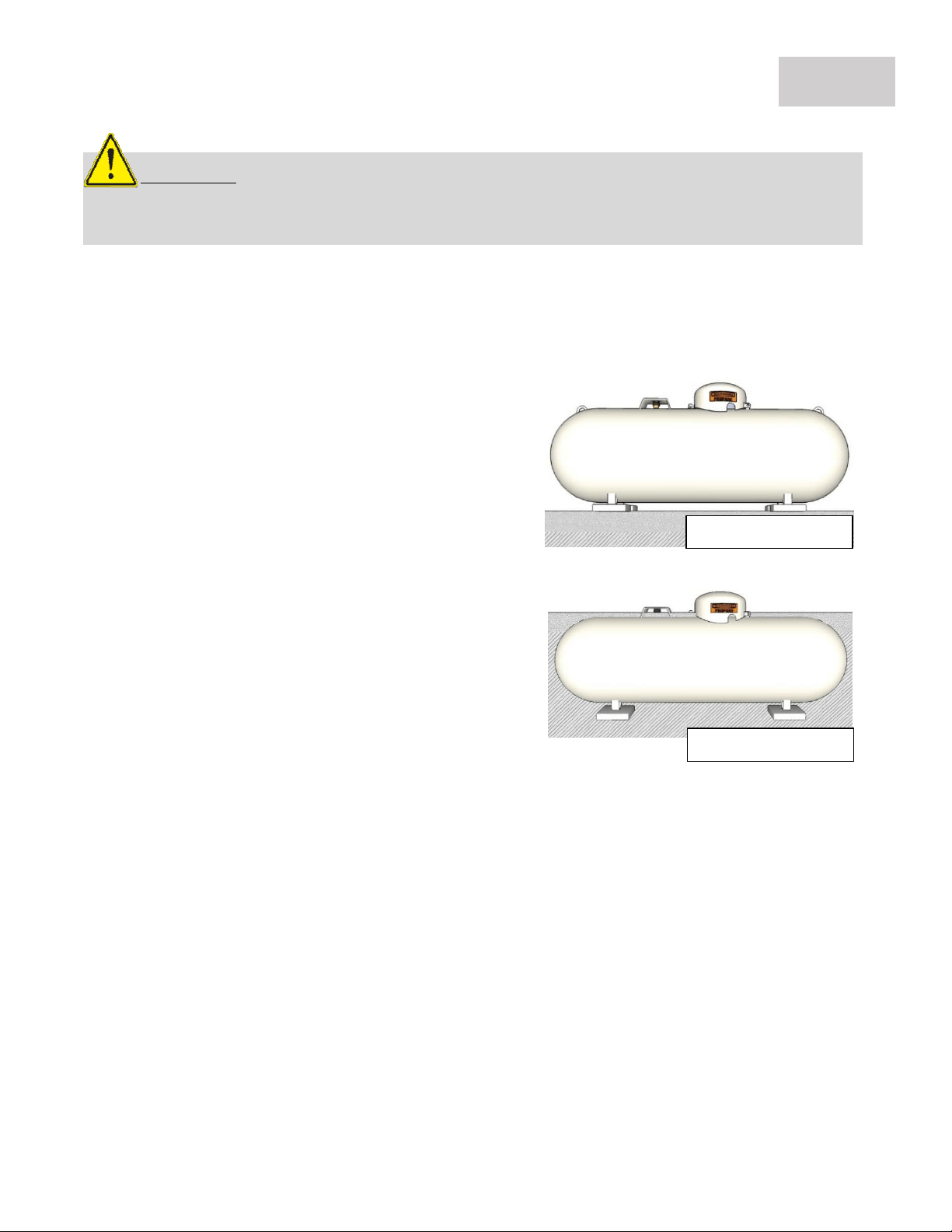
Propane is delivered to your home as a very cold liquid and is pumped into a specially designed storage
tank which is either Above or Below Ground. The liquid changes to gas before leaving the tank. Propane
tanks are typically painted white or silver to reflect heat and
prevent the pressure inside the tank.
If you have a side yard LP tank, it will be either Above or
Below Ground.
The cover on top of the tank protects several
components from weather and physical damage.
The tank shut-off valve, which you can close to
stop the flow of propane to your home in case of
a leak or other emergency.
The regulator, which controls the pressure of the
propane gas coming out of the tank.
The safety relief valve, which will pop open
automatically if the pressure inside the tank gets
too high. The valve will close again when the
pressure returns to normal.
The tank gauge, which shows the percentage of
propane in the tank.
Above Ground Tank
Below Ground Tank
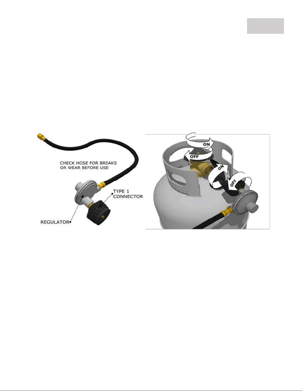
Medium Capacity LP Tank
The Type 1 connection system has the following features:
The system will not allow gas to flow
until a positive connection has been made. NOTE: The cylinder control valve must be turned off
before any connection is made or removed. The system has a thermal element that will shut off
the flow of gas in the event of a fire. The system has a flow limiting device which, when activated,
will limit the flow of gas to 10 cubic feet per hour. NEVER use grill without leak testing.
GAS SETUP
–
MEDIUM CAPACITY LP TANKS
PAGE 12
Follow Instructions:
The tank valve & all Knobs should be in the “OFF” position. If not, turn the knob clockwise until it
stops.
Insert the regulator inlet into the tank valve and turn the coupling nut clockwise until the coupler
tightens up (see picture above). Do not overtighten the coupler. Turn the main tank valve on and
turn the grill control valves on the unit to the “HIGH” position for about 20 seconds to allow the
air in the system to purge before attempting to light the burners.
NG Gas Hook-up
The Natural Gas grill is designed to operate on Natural Gas ONLY, at a pressure regulated at 7”water
column (W.C.) equipped with the correct natural gas orifices on the valves and a NG medium
pressure regulator on the supply line located near the grill and regulated at the residential meter.
GAS SETUP
–
NATURAL GAS INSTALLATION
PAGE 13
Follow Instructions:
The tank valve & all Knobs should be in the “OFF” position. If not, turn the knob clockwise until it
stops.
Insert the regulator inlet into the tank valve and turn the coupling nut clockwise until the coupler
tightens up (see picture below). Do not overtighten the coupler. Turn the main tank valve on and
turn the grill control valves on the unit to the “HIGH” position for about 20 seconds to allow the
air in the system to purge before attempting to light the burners.
GRILL START
-
UP
–
LIGHTING THE GRILL
PAGE 14
OPEN HOOD!
Ensure Grill Control Knobs
are In the OFF position, Turn
Knob to High Position.
2.
Light the Main Burners by Turning the
Right KNOB counter-clockwise to HIGH
To light IR-Burner turn the Left KNOB
counter-clockwise SLOWLY allowing gas
to completely fill the burner chamber.
(see page 19 for IR
-
Burner lighting)
3. You will hear a loud click as the
electronic lighter produces a spark.
Listen for the sound of the gas igniting
and look for a flame through the cooking
grids. If the burner does not light on the
first try, repeat immediately.
4. If the burner does not light in 5
seconds then wait five minutes until the
gas clears before attempting to light it
again. Repeat the procedure or try the
manual lighting options on next page.
5. Upon successful lighting, repeat the
process on the other burners you wish to
light.
6. To shut off the burners, rotate the
knob and turn to OFF.
7. It is normal to hear a popping sound
when the burners are turned off.
1. Stack charcoal briquettes or wood into
a pyramid-shaped pile on top of the
charcoal grate or pan. We recommend
using 2 pounds (approximately 30
briquettes) to start your fire, adding
more as needed. – CLOSE DRAWER -
4. Self-Starting Briquettes
If you don’t want to fool around with lighter fluid, there is one
more alternative—self-lighting charcoal briquettes. With
these, all you do is pile the briquettes on the grill, light them
with a match or butane lighter, and you have an almost instant
fire. Some grillers like to use these as starters, with a mixture
of regular briquettes. One thing to note, however: self-lighting
briquettes are not recommended for use with chimney starters.
3. Charcoal Chimney Lighter
A charcoal chimney starter is essentially a metal tube, usually
steel, with a handle on the side. Inside is a grate to hold the
briquettes and to keep them above the crumpled newspaper,
which goes in under the charcoal and is what starts the
briquettes. Ventilation holes line the bottom of the tube. The
goal is to start a charcoal fire without using lighter fluid or
other petroleum-based fuels. This is to avoid unpleasant taste
to the food, environmental regulations or for other reasons.
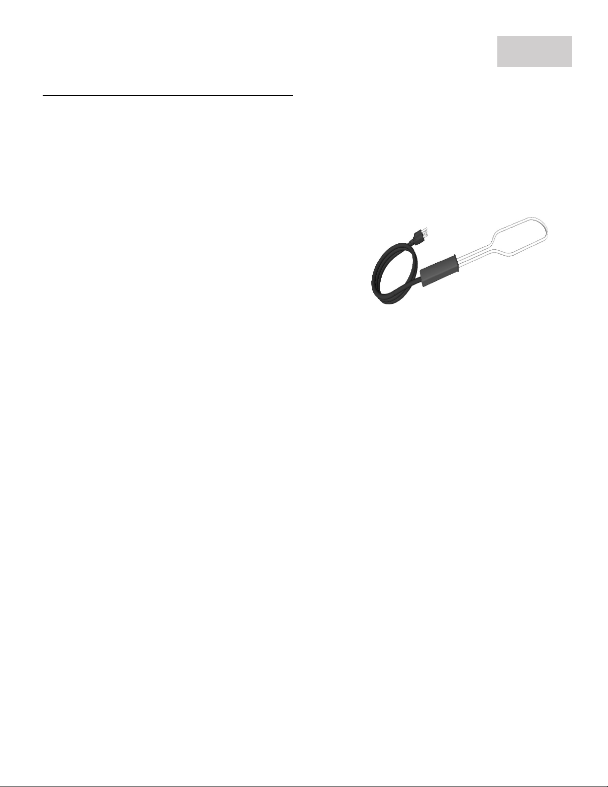
2. Electric Charcoal Lighter
Electric charcoal lighters look like an elongated outline of
a Ping-Pong paddle. That outline is the lighter element
loop that, when plugged in, glows like the heating
elements in a toaster.
1. Lighter Fluid (DO NOT USE IN
CONJUNCTION WITH GAS BURNERS)
Serious Injury or Fire will result!
Optional Charcoal Starters are not included
GRILL START
-
UP
–
ALT
ERNATIVE LIGHTING
PAGE 15

Zone Cooking
The Sunstone 30” Hybrid Grill has a single massive cooking zone controlled specifically by how the top
adjustable rack is positioned, and the front air intake slider is adjusted. Depending on how you
independently configure these components, will give you control over diverse types of cooking,
including Smoking, Indirect, Slow Cooking and Direct Cooking.
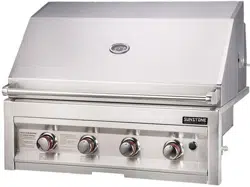
Heat Distribution
Knowing how to configure the different components will give you the very best possible food
positioning while grilling. Depending on how you position the Charcoal or Wood. The Cooking Rods
have Variable Spacing for different sized foods, and the upgradable Pro Sear Zone Grate will sear
your Steaks at over 800 Degrees depending on how hot the Charcoal or Wood is below. It is
important to play with many variations to find what way of grilling is best for you.
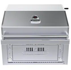
Grilling Combination
The Sunstone 30” Hybrid Grill is designed for an exquisite cooking experience with the use of three
separate grilling surfaces in one. This enables you to be simultaneously searing your food on one
side, while slow cooking or smoking on other side and slow simmer on top warming rack. The lower
drawer allows you to control how much either Charcoal or Wood materials you want to grill with also
use multiple types of mesquite wood for some amazing smoked flavors.
Indirect Cooking
Indirect cooking is the process of cooking your food without the heat source directly under your
food. You can sear meats over a high flame on one side of the grill while slow cooking on the other
side of the grill. It is like cooking in an oven and is generally used for larger cuts of meats but can
also be used for cooking foods that are prone to flare ups. Indirect Cooking will result in tender
foods every time you grill.
Direct Cooking
Direct cooking is the process of cooking your food directly over hot coals. This method is also
called Searing, Grilling or even Frying. Direct cooking is recommended for most grilling
applications, and the best place to perform Direct Cooking is in the place where the cooking
surface is the hottest. This type of cooking locks in flavor and juices while allowing the outer
surface to absorb smoke and food aroma that is produced as grease and drippings are vaporized
by the coals. The result is a crisp, flavorful outside with a tender, juicy inside.
Smoker/Steamer Box
Adding a smoker box to your cooking experience adds unique flavor to your food, you will
come to enjoy. Use it for either a smoker box with wood chips, or by filling with Water it
becomes a steamer box. While in use, remember to close the hood. There are many
different wood chips available on the market, the most common are mesquite and hickory.
Just remember to soak the chips for 30 minutes prior, for best results.
GRILL START
-
UP
–
USING THE GRILL
PAGE 16
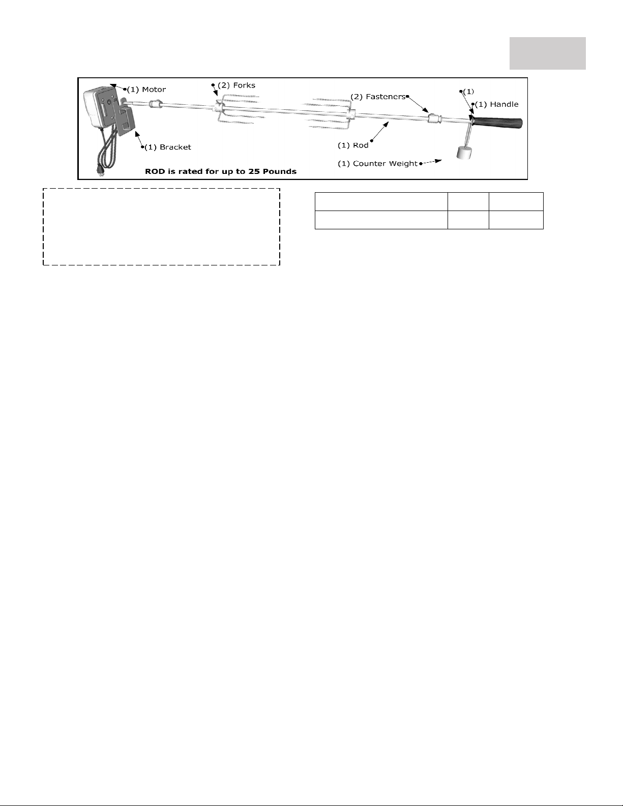
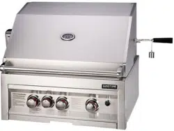
Rotisserie assembly can be purchased
individually either by individual item, or in a
complete set. The rotisserie assembly can also
be used with or without an infra-red back
burner.
Name
Qty.
Part No.
3 Burner Rotisserie set
1
P
-
RK
-
3B
Electrical Grounding Instructions:
The rotisserie motor is equipped with a three-prong grounding plug for your protection against electric shock. This
plug must be inserted directly into a properly grounded three-prong receptacle. Do not cut or remove the grounding
prong from this plug.
The rotisserie motor must be electrically grounded in accordance with local codes or, in the absence of local codes, in
accordance with the National Electrical Code, ANSI/NFPA 70-1990 or Canadian Electrical Code, CSA C22.1.
Do not use an extension cord to supply power to your grill. Such use may result in fire, electrical shock or other
personal injury. Do not install a fuse in the neutral or ground circuit. A fuse in the neutral or ground circuit may result
in an electrical shock hazard. Do not ground this appliance to a gas supply pipe or hot water pipe.
1.
Insert Rotisserie Motor into Motor Bracket Assembly.
2. Slide Prong Forks with the prongs facing away from the handle into Spit Rod. So that any food item
will be in the center between the two four prong forks.
3. Assemble Key Washer, Counter-balance and handle to Spit Rod. Slide Shaft Collar with long end
towards handle.
4. Insert motor extension cord three prong plug into an adjacent grounded GFCI receptacle outlet.
5. Before placing food item on forks when the rotisserie is being operated exclusively, it is strongly
recommended that a pan be placed on the grilling grids, beneath the food to catch the meat
drippings. This will prevent excessive buildup of drippings on the grids and facilitate cleaning.
When food item is placed on rotisserie, be sure that all Bolts are tightened securely.
6. Preheat the grill by setting all the burners on high, once hot, turn off all but the rear burner. The
spit hangs over the center, so that the meat is not directly over the heat. Place a drip pan on the
grill below the meat. Add about 1/2 inch of water to the drip pan.
7. Place the first pair of prongs onto the spit, then push the meat onto the spit and into the
prongs. Add the other set of prongs and push them into the meat securely anchoring it onto
the spit. Tighten the wing nut that holds the prongs in place and attach the spit to the brackets
on either side of the rotisserie.
8. The rotisseries rod comes with a counter balance weight, adjust it as needed. Start the motor
and make sure the meat is balanced on the spit so that it turns evenly. You may need to adjust
the grate and drip pan if your meat is large. Make sure the meat can turn with no obstructions.
9. Close the lid while the rotisserie does its job. The rotation evenly melts the fat in the meat and
naturally bastes the meat, but you may wish to baste with a mop sauce occasionally during
grilling. Check the meat with a meat thermometer for doneness before turning off the heat.
When done, remove the spit using insulated oven mitts. Place the meat on a clean platter and
cover it with foil while it rests.
GRILL START
-
UP
–
ROTISSERIE SETUP
PAGE 17
WARNING: Never stand with your head directly over the Grill when preparing to light the Rotisserie
burner, to prevent possible bodily injury. Never operate Rotisserie Burner with main (other) burner(s)
“ON”. Warming Rack must be removed when Rotisserie Burner is ON.
Rotisserie Cooking Tips
Rotisserie is mostly used to cook large piece of meat and poultry to assure slow, even cooking. The
constant turning provides a self-basting action, making food cooked on a rotisserie exceptionally moist
and juicy. Rotisserie cooking generally requires 1 ½ to 4½ hours to cook depending on the size and type
of meat being cooked. You can have rotisserie cooking with indirect heat or with infrared rotisserie
burner. Preferred by professional chefs over other methods, the intense heat is ideal for searing in the
natural juices and nutrients found in quality meat. For successful rotisserie, the meat should be
centered and balanced as evenly as possible on the spit rod to avoid overworking the rotisserie motor.
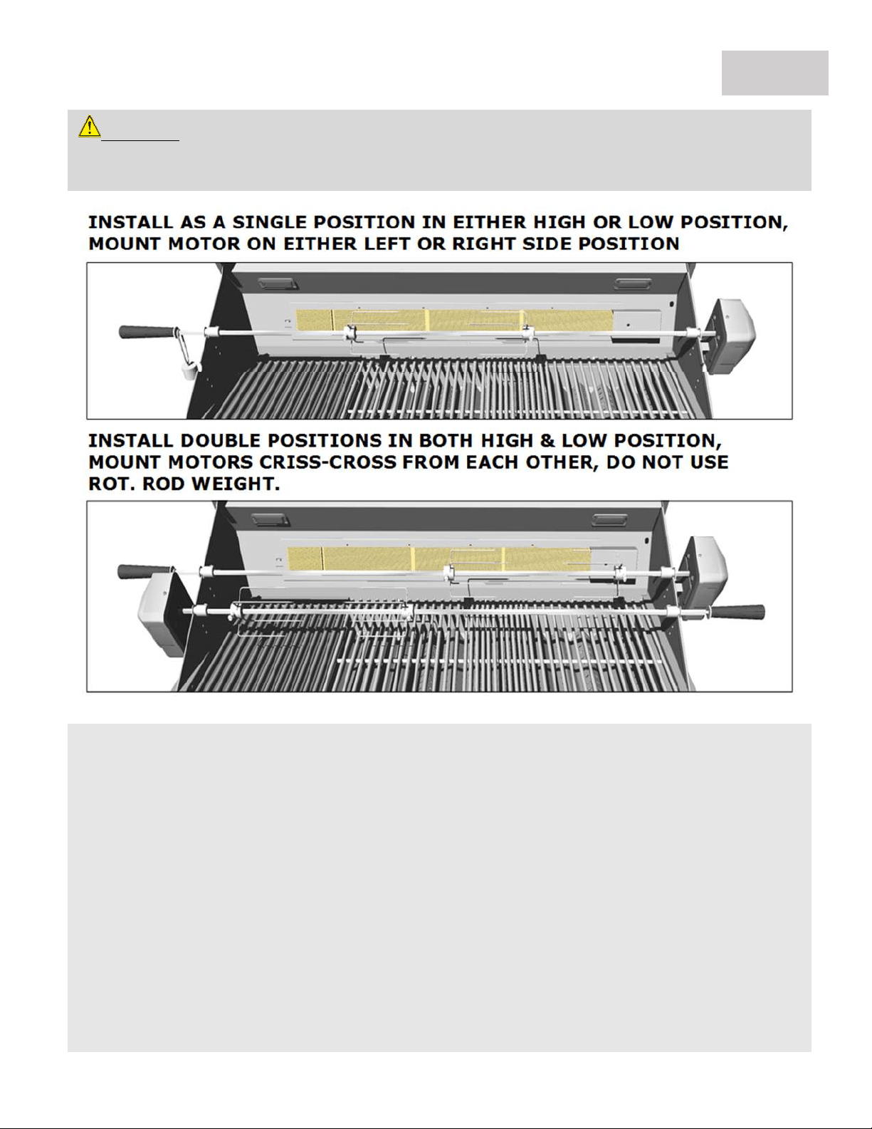
Your Grill is designed with High & Low Spit Rod positions, the Low position centers your meat in the
grills body, while the high position brings it closer to the back Infra-Red burner for High Heat Searing.
Also, you can place up to Two Rotisserie Rods and Motors Criss-Crossed as shown in the above example
for Setup of the Rotisserie Assembly.
GRILL START
-
UP
–
ROTISSERIE COOKING
PAGE 18
Open Hood
Ensure Burner Control
Knobs are in the OFF
position
1. Push the knob in and SLOWLY turn
the Left KNOB counter-clockwise to
HIGH. Allow Gas to Completely Fill
the IR Burner
chamber.
2. You will hear a loud click as the
electronic lighter produces a spark.
Listen for the sound of the gas igniting
and look for a flame spreading across
the ceramic plates from left to right. If
the burner does not light on the first
try, repeat immediately.
3. Repeat this until IR Burner lights all
the way across and stay on. There is a
Brass Wire called the Thermocouple, it
must be heated all the way down to
the valve for the gas to stay on.
TIP: If IR-Burner does not stay lit, try
running the bottom burners first for 10-15
minutes, this will heat the Thermocouple
and help the IR
-
Burner stay lit.
5. To shut off the burners, rotate the
knob and turn to OFF.
6. It is normal to hear a popping sound
when the burners are turned off.
GRILL START
-
UP
–
IR BURNER LIGHTING
4. If the burner does not light in 5
seconds then wait five minutes until the
gas clears before attempting to light it
again. Repeat the procedure if not
lighting. The back IR-Burner requires
additional time for first time lighting.
PAGE 19
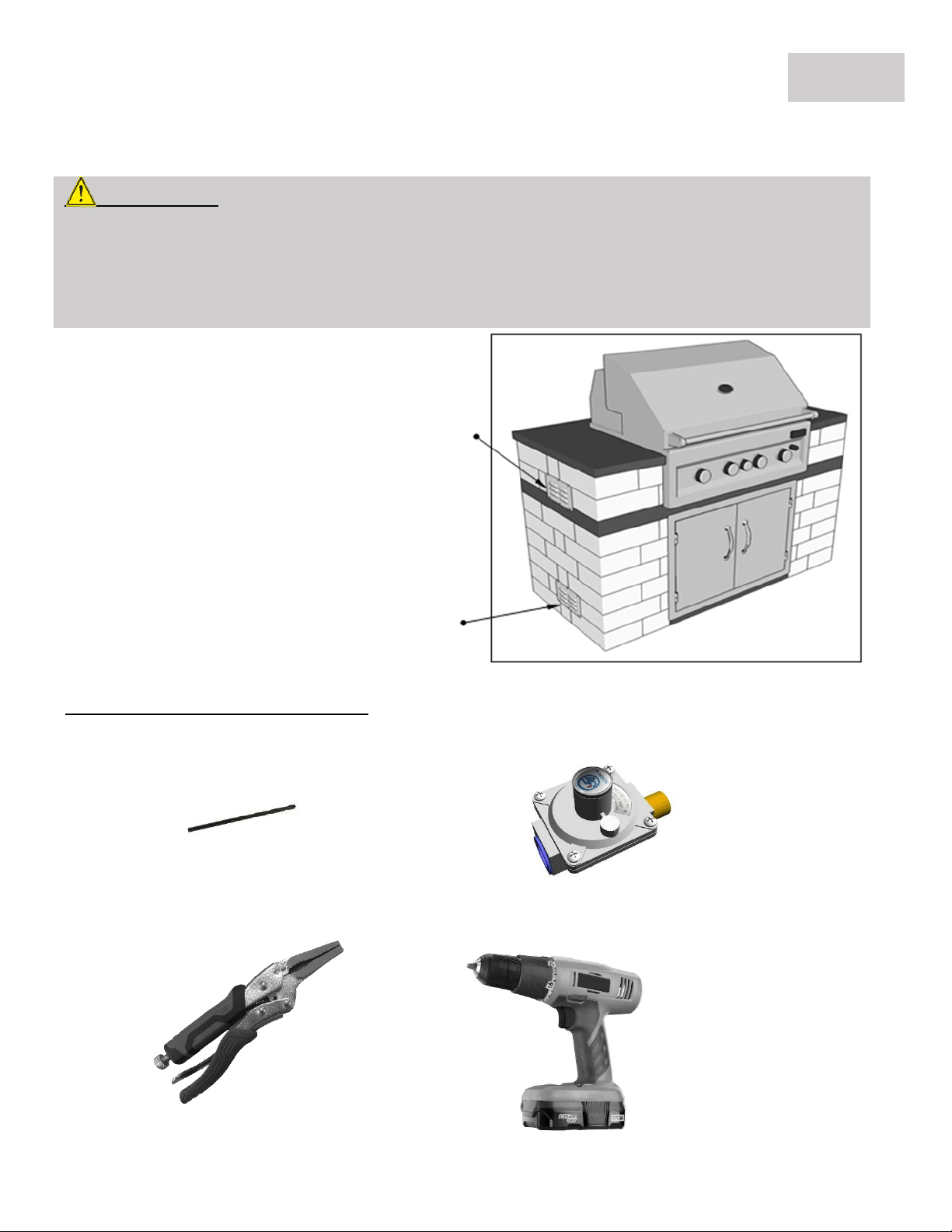
Island Safety Vent Installation for either Liquid Propane or Natural Gas
Grill LP to NG Gas Conversion
This Gas Conversion requires the following parts (Included in Kit)
(1) #50 Drill Bit (1) NG Regulator
with 3/8” Flare Adapter
The following tools are recommended (Not Included in Kit)
Wrench Power Drill
For Natural Gas
Natural Gas (NG) is lighter and will raise to upper
end of structure upon leak. Outdoor Kitchen Islands
housing Natural Gas Appliance must have several
vents located at the approximate level as the
Appliance Control Panel, were Knobs are located.
For Propane Gas
Liquid Propane Gas (LP) is Heavier and will lower to
base of structure upon leak. Outdoor Kitchen Islands
housing Propane Gas Appliance must have several
vents located within 4" to 6" from ground level.
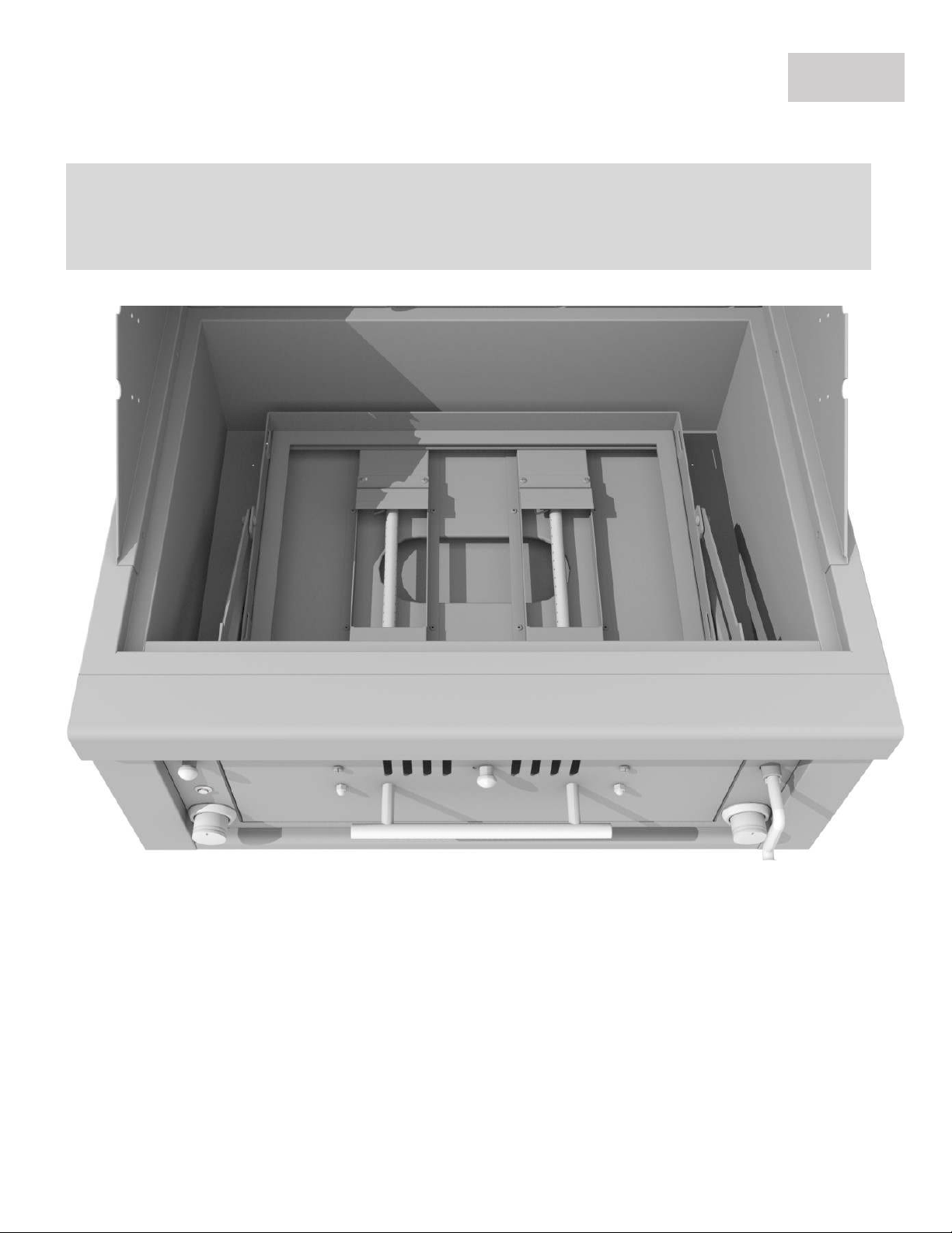
IMPORTANT!
The Best time to perform this conversion is before grill has been installed into island enclosure. As you
will need access Multiple parts of the Back Underside of Grill where Gas Line hooks up and two positions
of Flare Adapters. Accessing this location afterwards requires either removing the grill from island or
crawling underneath grill through an access door to reach back underside of grill.
GAS CONVERSION
–
REQUIRED TOOLS
PAGE 20
The Following Steps illustrate the LP to NG Flare adapter change to the RIGHT
Side Flare Adapter ONLY. You will also be required to follow the same steps
when modifying the LEFT Side Flare Adapter to NG gas type.
1. Reveal Grill Firebox
Remove from the Grill ALL Burn Trays, Cooking Grates, and clean out any residue. Turn the Burn Tray
Crank so that the Burn Tray Rack is placed in the lowest position. Now look towards the back of each
burner position Left and Right, you will notice a Flare
Adapter coming in though the back wall panel.
GAS CONVERSION
–
REVEAL FIREBOX
PAGE 21
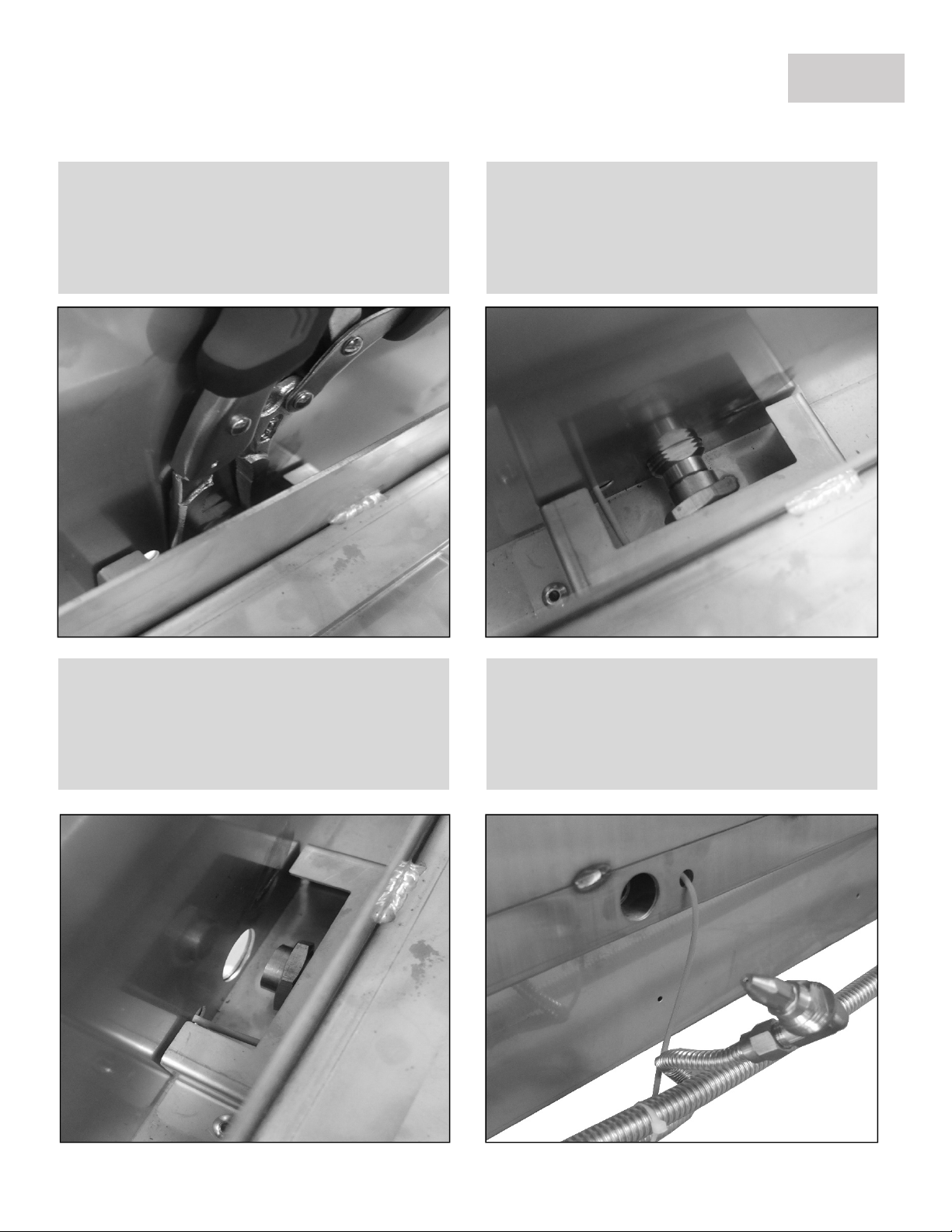
2. Unscrew Brass Flare O-Ring
Using the recommended “Needle Nose Plyers” –
unscrew the brass O-Ring which is securing the
Flare Adapter tightly in place, with its nose end
inserted into the open burner hole port.
3. Stow-Away the O-Ring
Important! Be sure to slide the brass O-Ring, if
O-Ring falls below it may be very difficult to pull
it back up as it is a very small area with limited
access under burner compartment.
4. Push the Flare Adapter Out
Push the Flare Adapter out through the port-
hole, while keeping the Brass O-Ring stationary
on the end of Burner.
5. Locate the Flare Adapter in Back
If the Flare Adapter has not been pushed out all
the way, do that now by pulling it out, and
rotate it slightly revealing the Orifice Hole at tip
the Tip of the Flare Adapter Cone.
GAS CONVERSION
–
FLARE
ADAPTER
PAGE 22
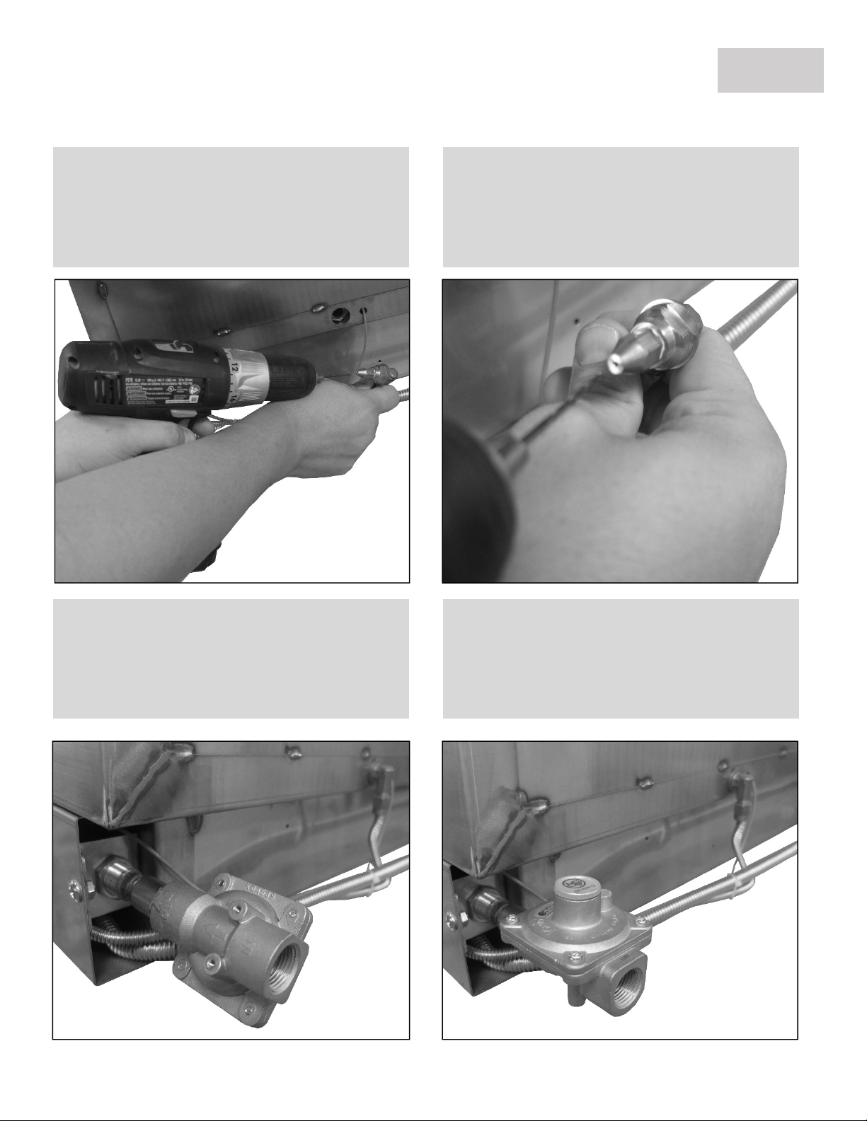
6. Prep #50 Drill Bit & Power Drill
Secure the #50 size Drill-Bit and install it into the
Power Drill. While grasping the Elbow of the
Flare Adapter – Align to the tip of drill bit so
your drill-bit is perfectly aligned to orifice hole.
7. Drill the Adapter Orifice
Aligning Drill to Flare Adapter, Push the Spinning
Drill into the center of Orifice Hole approx. 1/8
th
Inch then pulling out, lastly blow some air into
tip clearing any small particles.
8. Screw on the NG Regulator
Fasten on the NG Regulator, with the Female
Flare Adapter connecting to the Right Back Side
Gas Manifold Male Flare Adapter. Notice Arrow
indicating direction of Gas Flow.
9. Finalize LP to NG Conversion
The NG Regulator will have a ½” Female Flare
Adapter on other end, try our 18” Black Hose, or
a Quick Disconnect – Always have a Licensed
Plumber make this final connection.
GAS CONVERSION
–
NG
REGULATOR
PAGE 23
GAS CONVERSION
–
IR BURNER
IR BURNER GAS CONVERSION
The following section is for converting the Sunstone 30” Hybrid Grill Back IR Burner for either LP to NG or
NG to LP.
PAGE 24
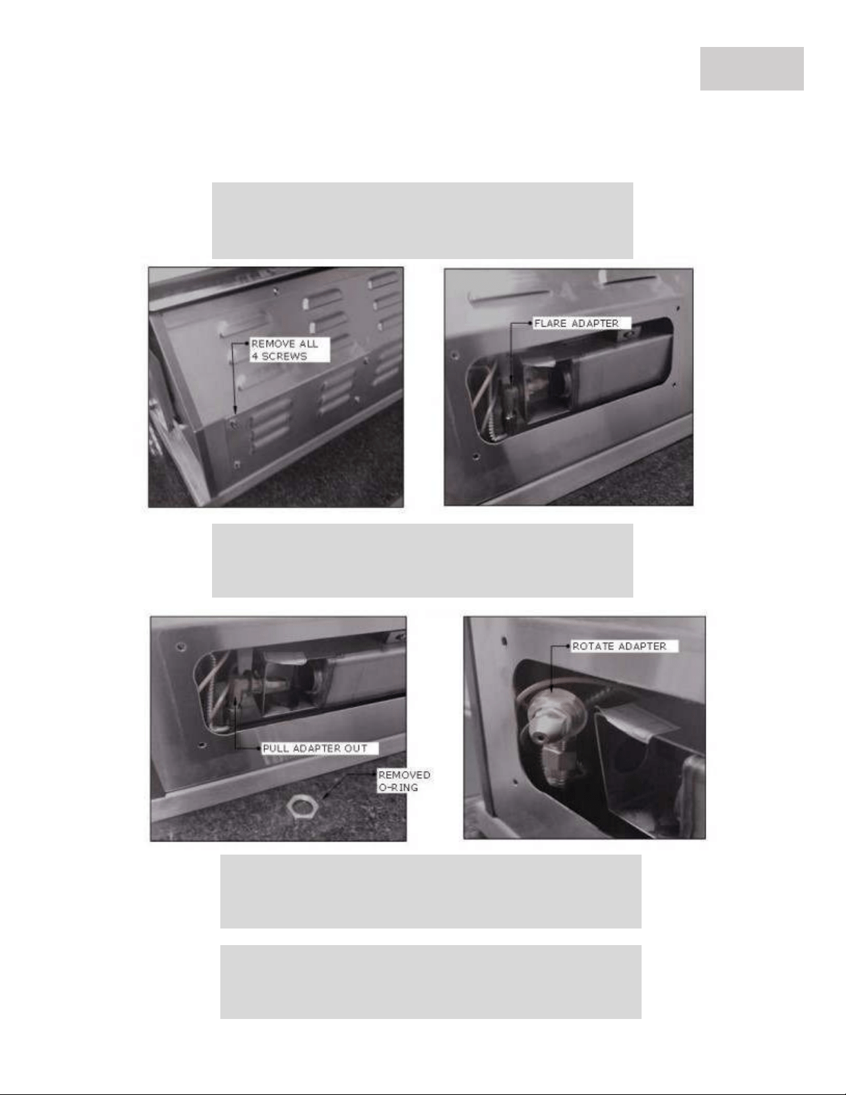
10. Locate Back Right Vent Panel
Remove panel with 4 screws, locate Brass Flare Adapter
mounted on the inside compartment.
11. Remove Brass O-Ring to Release Flare
Once the flare is removed, pull the orifice end out so it is
accessible.
12. LP to NG Gas Conversion
For converting from LP to NG, use #50 Drill Bit and drill out
the Center Flare Hole, making it larger as Shown in image.
13. NG to LP Gas Conversion
For converting from NG to LP, you must remove the Flare
and replace with new LP Flare with smaller
Orifice Hole.

Q. LED Light is not functioning while interior lights are ON
A. Likely your LED Light has malfunctioned due to the grill being overheated, or there may be a loose wire on
the internal control circuit board. You can access these components by sliding the grill out from your island
approx. 6 Inches, there are 4 screws on either side holding the front control panel to grill body, and 4 Alan
Wrench Screws on the inside facing towards front panel, you will see 4 Holes. Removing these screws will
allow the main control panel to be removed revealing the internal LED light and Circuit Board. You can then
easily unplug and replace LED light with new one or check for other loose connections.
Q. Either One or Both Interior Lights do not work but LED Light works
A. Most often the interior Halogen Lights will burn out one at a time, if both are out at the same time, you
could have a connection issue. Check the Plug in the back bottom Left of grill, the plug consists of two sockets
on either side, check to make sure each is securely pushed in. If all the Lights do not work, then it is either
unplugged or the Transformer has malfunctioned. Each Halogen light can be replaced by unscrewing a single
screw per light located on left sides of light cover, the entire light box needs to be removed, and there are two
small black wires hard-plugged into back of light. Use a pair of plyers to remove these, replacing to new
Halogen Light box, again use a pair of plyers to push each wire into each socket of light box, Test light is
working before inserting back into hole and again tightening the small screw on left outer side.
Q. The Gas Burners flame is very Low
A. If your grill is using a 25 Pound Portable tank and is directly connected to grill with no other appliance, you
may have a Spider Web or other clog in the gas Pipe. If your grill is connected to a Side Yard 500 Gallon Tank,
there may be an issue with the Regulator – either it is a Low-Pressure Regulator being used, or not enough gas
pressure is being allowed to the grill. If you have any T-Connections in gas line going to other outdoor
Appliances like a Fireplace or Side Burner, this can also greatly diminish gas flow.
TROUBLE SHOOTING
PAGE 25

GRILL WARRANTY
PAGE 26
ATTENTION
:
The Hybrid Grill must be installed according to the product manual. If your burner
installation does not meet the Basic Setup Instructions ALL WARRANTIES MAY BE VOID.
SUNSTONE SERIES 30” GAS HYBRID CHARCOAL GRILL WARRANTY
***All Warranties Start from the Date of Purchase***
LIMITED LIFETIME WARRANTY
Sunstone Stainless Rod Cooking Grids and Stainless-Steel Housings (including liners, frames, firebox and hood and all exterior
grill faces) are warranted for as long as you own the Sunstone Barbecue Grill against all factory defects. This warranty does
not cover against consumer usage wear and tear from using the grill as all grilling methods will erode the 304 Stainless Steel
Materials.
LIMITED LIFETIME WARRANTY WITH ONE YEAR BURNER REPLACMENT
The Stainless-Steel Gas Tube Burner is warranted for as long as you own the Sunstone Barbecue Grill against all factory
defects. In addition, the Burner is covered for the first full year from date of purchase with FREE replacement against all wear
and tear. This warranty covers the burner only, it does not cover the cost of a service tech to replace the burner.
LIMITED ONE-YEAR WARRANTY
All other grill components including, thermometer, light assemblies, gas-valves, piezo-igniters, springs, all electrical wire are
warranted to be free from defects in material and workmanship for a period of one year from the original date of purchase.
LIMITATIONS & EXCLUSIONS
1. SUNSTONE warranty applies only to the original purchaser and may not be transferred.
2. SUNSTONE warranty is in lieu of all other warranties expressed or implied and all other obligations or liabilities
related to the sale or use of its grill products.
3. SUNSTONE warranty shall not apply, and SUNSTONE is not responsible for damage resulting from misuse, abuse,
alteration of or tampering with the appliance, accident, hostile environment, flare-up fires, improper installation, or
installation not in accordance with the instructions contained in the User Manual, or the local codes.
4. SUNSTONE is not responsible for warping of component parts due to overheating or using in a way not in line with
the product manual.
5. SUNSTONE shall not be liable for incidental, consequential, special or contingent damages resulting from its breach
of this written warranty or any implied warranty.
6. Some states do not allow limitations on how long an implied warranty lasts, or the exclusions of or limitations on
Consequential damages. This warranty gives you specific legal rights and you may have other rights, which vary
from state to state.
7. No one has the authority to add to or vary SUNSTONE warranty, or to create for SUNSTONE any other obligation or
liability in connection with the sale or use of its products.
8. SUNSTONE DOES NOT COVER FOR WARPING OF STEEL DRAWER, GRATES, OR ANY OTHER COMPONENT FROM THE
RESULT OF MISUSE OR OVERHEATING OF COMPONETS.
WHAT IS NOT COVERED. & INTERNET PURCHASE DISCLAIMER
SUNSTONE shall not be responsible for and shall not pay for the following Installation or start-up.
1. Service by an unauthorized service provider and the cost of a service tech of any warrantied parts.
2. Damage or repair due to service by an unauthorized service provider or use of unauthorized parts.
3. Damage caused by accidents, abuse, alteration, misuse, installation that is not in accordance with the instructions
contained in the User Manual, or local codes.
4. To correct normal adjustments or settings, due to improper installation, commissioning or local gas supply
properties.
5. Shipping and handling costs, export duties, or installation cost.
6. The cost of service calls to diagnose trouble; or Removal or re-installation cost.
This warranty applies to the original purchaser with invoice or proof of purchase and covers Sunstone products intended for personal, family or household
usage only. It does not apply to surface rust, corrosion, oxidation or discoloration, which may occur due to moisture or overheating, unless the affected
component becomes inoperable. This warranty does not cover parts becoming defective by misuse, accidental damage, improper handling and/or
installation. It does not cover labor or labor related charges. It specifically excludes liability for indirect, incidental or consequential damages. Some states
do not allow the exclusion or limitation of incidental or consequential damages, so the above exclusion or limitation may not apply to you. This warranty
gives you specified legal rights and you may have other rights which may vary from state to state.
For additional information regarding this warranty, or information on how to place a warranty claim, contact your authorized Sunstone dealer.