Loading ...
Loading ...
3 60-0830—4
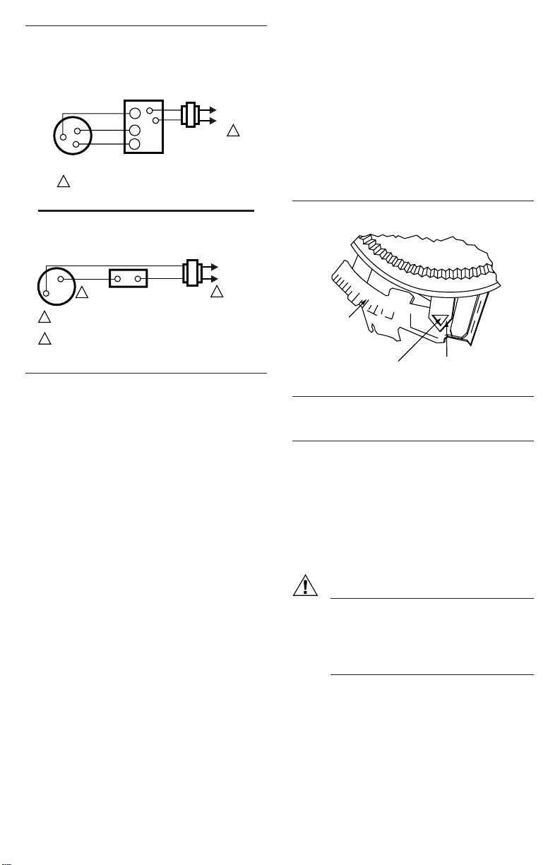
Fig. 6—T87F used for Series 20, 3-wire, spdt
control of low-voltage motors and electric
radiator valves. Used in applications where
thermostat makes contact on both a rise and
fall in room temperature.
RED
WHITE
BLUE
137421A
WALLPLATE
W
Y
R
B
W
R
TR
L1
(HOT)
L2
THREE-WIRE SPDT
VALVE OR MOTOR
POWER SUPPLY. PROVIDE DISCONNECT MEANS
AND OVERLOAD PROTECTION AS REQUIRED.
M5319
1
1
Fig. 7—T87F used in cooling-only system.
2. Let the system operate for one minute before read-
ing the ammeter.
3. Move the anticipator indicator to match the amme-
ter reading.
A slightly higher setting to obtain longer burner-on
times (fewer cycles per hour) may be desirable for some
systems.
RECALIBRATION
The T87F is calibrated at the factory and no recali-
bration should be necessary. If the thermostat is accu-
rately leveled and still appears to be out of calibration,
order 104994A Calibration Wrench. Instructions for
recalibrat-ing are furnished with the wrench.
Fig. 8—Setting heat anticipator current rating.
LONGER
.15
.12
.2
.6
.8
1.0
.5
.4
.3
HOLE SUITABLE FOR
PENCIL POINT
TO MOVE INDICATOR
HEAT
ANTICIPATOR
INDICATOR
SCALE
M1368
Checkout
HEATING
Turn down temperature setting to the lowest point. If
subbase or remote switching is used, move system switch
to HEAT position. Raise temperature setting until heat-
ing equipment starts. This point should be at room tem-
perature as indicated on the thermometer. Slowly turn
back dial. Heating equipment should stop when dial has
been turned below room temperature.
COOLING
CAUTION
1. Do not operate cooling if outdoor tempera-
ture is below 50° F [10° C]. Refer to manu-
facturer recommendations.
2. Allow five-minute off-time after compres-
sor has been run to avoid compressor dam-
age.
If T87F controls cooling, move system switch (if
used) to call for COOL and lower setting until cooling
equipment starts. Raise setting above room temperature
and cooling system should shut down. Make certain all
equipment properly responds to the thermostat.
MOUNTING THERMOSTAT TO WALLPLATE
OR SUBBASE
To remove standard cover, pull ring outward with
fingertips, pressing lightly on dial with thumbs.
To remove locking cover, loosen the three screws
along the cover edge with the Allen wrench supplied.
Remove the cover as indicated above.
Remove and discard the plastic insert protecting the
mercury switch.
Align the thermostat over the wallplate and tighten
the three captive mounting screws. These captive screws
complete the electrical connections to the thermostat.
Adjust heat anticipator to match current rating of pri-
mary control. See Fig. 8.
HEAT ANTICIPATOR SETTING
If the T87F is used for 3-wire, spdt, heating-only
(Series 20) control (Fig. 6), set the heat anticipator for
1.2 (far left end of scale). A fixed resistor-type heater is
provided in the 137421A or 198170A Wallplate for this
application. For other control applications, proceed as
follows.
Adjust anticipator to match current rating of primary
control. Rating is usually stamped on the control name-
plate. Move the indicator to the marking that matches
this rating. Indicator may be moved with fingers or
pencil point through the hole shown in Fig. 8. If the
current rating is not given, proceed as follows before
mounting the thermostat:
1. Connect an ac ammeter of appropriate range (0 to
2.0A, for example) between the R and W terminals on
the wallplate or subbase.
Y
R
THERMOSTAT WALLPLATE
OR SUBBASE
COOLING
CONTACTOR COIL
L1
(HOT)
L2
POWER SUPPLY. PROVIDE DISCONNECT MEANS AND
OVERLOAD PROTECTION AS REQUIRED.
ONLY R AND Y TERMINALS ARE USED FOR COOLING ONLY.
1
2
1
2
M3516
Loading ...