7210940100R17
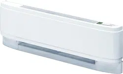
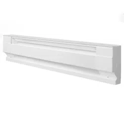
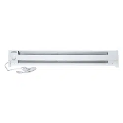
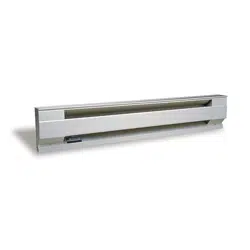
Linear Convector Baseboard
LC Series
PLACEMENT OF THE LINEAR CONVECTOR
BASEBOARD
Linear Convector Baseboards are high performance heaters de-
signed to operate at higher outlet temperatures than conventional
baseboard heaters. They can be directly mounted onto drywall, plas-
ter, wood or concrete walls. Due to the higher outlet temperature, the
wall surface can reach temperatures of 160º F (71º C) or above and
some materials may discolor or deform at these temperatures, e.g.
vinyl or plastic. In these cases the heater can be mounted with an
offset from the wall and oor to reduce the temperature being applied
to those materials. By installing the heater with the provided Installa-
tion Optimizer kit, the temperature of the wall above the heater can
be reduced to 129º F (54º C).
!
NOTE: If the unit is being installed on a newly constructed wall,
ensure that all products that have been applied are fully cured accord-
ing to manufacturer’s instructions, before operating the unit.
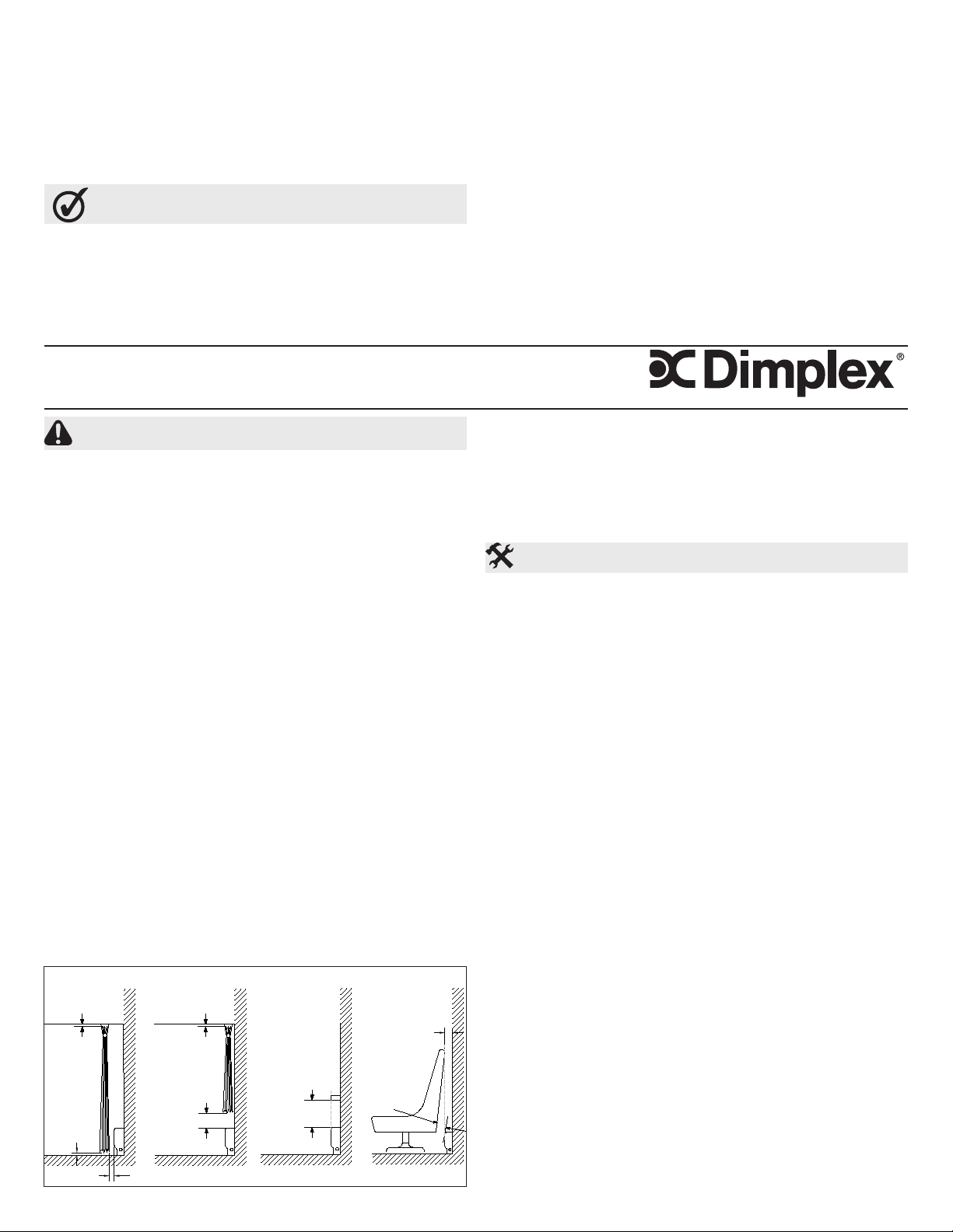
RECOMMENDATIONS FOR LOCATING DRAPES AND
FURNITURE NEAR HEATER (FIGURE 1)
!
NOTE: Any objects or materials that are located within the distances
outlined below should not discolor, nor distort dimensionally (stretch
or shrink) upon extended exposure ( up to 1000 hrs.) to temperatures
of 200º F (93º C).
For most satisfactory operation of the heaters and minimum effect on
drapes, furniture and objects in close proximity, the following recom-
mendations should be observed:
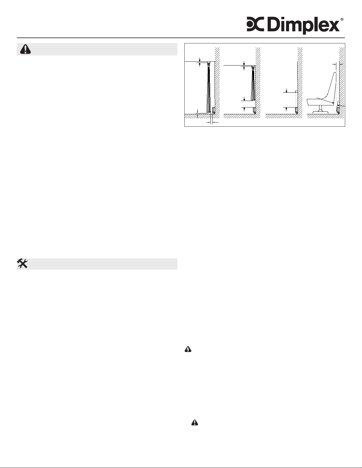
1. Full Length Drapes: Hang drapes so there is at least 1.5” (3.8 cm)
between the top of the drapes and the ceiling, at least 1.5” (3.8cm)
between the bottom of the drapes and the nished oor covering
(such as carpet, if used) AND at least 3” (7.6 cm) between the front
Installation Instructions
IMPORTANT INSTRUCTIONS
When using electrical appliances, basic precautions should always
be followed to reduce the risk of re, electric shock and injury to per-
son, including the following:
1. Read all instructions before using this Linear Convector Base-
board.
2. Heater and controls should be installed by a qualied contractor.
Wiring procedures and connections should be in accordance with
the National Electric Code (CEC & NEC) and local codes.
3. A Linear Convector Baseboard has hot and arcing or sparking
parts inside. Do not use it in areas where gasoline, paint or am-
mable liquids are used or stored.
4. This Linear Convector Baseboard is hot when in use. To avoid
burns, do not let bare skin touch hot surfaces. Keep combustible
materials such as: furniture, pillows, bedding, papers, clothes and
curtains away from Linear Convector Baseboard.
5. To prevent a possible re, do not block air intakes or exhaust in
any manner. Do not use on soft surfaces like a bed where open-
ings may become blocked.
6. Do not insert or allow foreign objects to enter any ventilation or
exhaust opening as this may cause an electric shock or re, or
damage the Linear Convector Baseboard.
7. Do not install these Linear Convector Baseboards against com-
bustible, low density cellulose bre surfaces or vinyl wallpaper.
8. Do not locate these Linear Convector Baseboards below any
electrical convenience receptacles.
9. Check Linear Convector Baseboard nameplate ratings to be sure
Linear Convector Baseboard voltage is the same as the service
supply. (The nameplate is located below the right side of the heat-
ing element.)
10. HIGH TEMPERATURES: Keep electrical cords, furniture, drap-
eries or any other blocking material away from the Linear Con-
vector Baseboard.
SAVE THESE INSTRUCTIONS
Figure 1
A B C D
vertical surface of the heater and the nearest fold of the drapes
(opened drape). (Figure 1A)
2. Shorter Length Drapes: Hang drapes so there is at least 1.5” (3.8
cm) between the top of the drapes and the ceiling, and at least 6”
(15.3 cm), preferably more, between the bottom of the drapes and
the top horizontal surface of the heater. (Figure 1B)
3. Furniture: Place furniture no closer than 3” (7.62 cm) from the front
of the Linear Convector Baseboard. (Figure 1D)
4. Overhanging Solid Objects (Except Plastic): Position Linear
Convector Baseboard so there is at least 14” (35.6 cm) between
the top of the heater and any solid object that obstructs or redirects
the vertical air ow out of the top of the unit. (Figure 1C)
5. Overhanging Plastic Objects: All Plastic items that cannot with-
stand extended exposure to temperatures 60º C or higher should
be kept a minimum of 20” (50.8cm) above the unit. (Figure 1C)
!
NOTE: Ensure that when 2 Linear Convector Baseboards are in-
stalled near the same corner they are both a minimum of 6” (15.3
cm) from the corner.
FACTORY WIRING OF THE LINEAR CONVECTOR
BASEBOARD
All Linear Convector Baseboards have provisions for connection
to either end of the Linear Convector Baseboard. The lead wires at
either end are factory spliced with wire nuts as a closed circuit. The
circuit may be opened at either wire nut connection to make connec-
tions to the power supply and/or to the desired controls. (See Wiring
Diagrams)
CONTROLS (not included)
A thermostat control (wall mounted or built-in) is required to operate
this unit. Typical Dimplex controls:
• Built-in thermostat kits: DTK-SP, DTK-DP, DTKT-SP or DTKT-DP
• External line voltage thermostats: TS521W, TD522W, HTC521W,
HTC525W, HTC621W or HTC625W
• Built-in low voltage relay: BLLVCxx or BLLVD
INSTALLATION
WARNING: Disconnect power supply before installation to pre-
vent electric shock.
1. Unpack and place Linear Convector Baseboard on oor face up,
use packaging to protect oor if required. Remove front covers.
!
NOTE: Remove the center cover, by releasing the top rst.
!
NOTE: Heater ns can be easily bent. For optimal performance
ensure that they remain vertical.
2. Orient unit in desired location and mark pilot holes - top and bottom
at both ends and at least one set in middle.
3. Wire unit as per diagrams on page 6 and National and Local Elec-
trical Codes.
CAUTION: Connect heaters to a branch circuit used only for
permanently installed heater and protected by over current devic-
es rated or set at no more than 30 amperes. The total connected
load should not be more than 80% of the rating of the over current
devices. It may cause a re hazard if not installed and maintained
Min.
1.5" (3.8 cm)
Min.
1.5" (3.8 cm)
Min.
1.5" (3.8cm)
Min.
3" (7.6 cm)
Min.
3" (7.6 cm)
Min.
3" (7.6 cm)
Min.
6" (15.3 cm)
Min.
See Item 4 & 5
for Dimension
Minimum
6" (15,3 cm)
Minimum
3" (7,6 cm)
Minimum
3" (7,6 cm)
Minimum
3" (7,6 cm)
Minimum
1.5" (3,8cm)
Minimum
1.5" (3,8 cm)
Minimum
1.5" (3,8 cm)
Minimum
Voir le point 4 et 5
pour la dimension
Lorsqu’un appareil électrique est utilisé, il est important de toujours
prendre des précautions de base pour réduire les risques d’incendie,
de chocs électriques et de blessures, y compris les suivantes :
1. Lire toutes les instructions avant d’utiliser le Plinthe-convecteur
linéaire.
2. Les plinthe-convecteurs linéaires et les contrôles doivent être
installés par un entrepreneur qualié. Les procédures et les
connexions du câblage doivent être conformes au Code national
de l’électricité (CEC et NEC) et aux codes locaux.
3. Toutes les appareils de chauffage contiennent des pièces qui
chauffent et produisent un arc électrique ou des étincelles.Ne pas
faire fonctionner l’appareil dans des endroits où de l’essence, de
la peinture et autres produits inammables sont utilisés ou entre-
posés.
4. Le Plinthe-convecteur linéaire devient chaud lorsqu’il est en
marche. Pour éviter les brûlures, ne pas toucher les surfaces
chaudes. Tenir le Plinthe-convecteur linéaire éloigné des maté-
riaux combustibles comme : meubles, oreillers, literie, papier,
vêtements et rideaux.
5. Pour éviter un incendie, ne pas obstruer les entrées ou la sortie
d’air d’aucune façon. Ne pas utiliser l’appareil sur des surfaces
instables, comme un lit, où les ouvertures risquent d’être obs-
truées.
6. Ne pas introduire ou permettre l’introduction de corps étrangers
dans la prise d’air de ventilation ou la bouche de sortie d’air, car
cela peut occasionner des chocs électriques, provoquer un in-
cendie ou endommager le Plinthe-convecteur linéaire.
www.dimplex.com2
Warranty
The Manufacturer warrants the Linear Convector Baseboard and components
of the enclosed product against any defect in material or workmanship for a
period of one year from the date of purchase, with the exception of the elements
which are warranted to be free from defect in material and workmanship for ten
years. In full satisfaction of any claims under this Warranty the Manufacturer
will repair or replace without charge, in its factory or in the eld as it alone may
decide, any parts which in its opinion are defective.
The Manufacturer shall not be responsible for any transportation or shipping
costs in relation to such repair or replacement except as specically assumed
by it. Misuse of this product or repairs by persons other than the Manufacturer’s
authorized personnel without the Manufacturer’s written approval, will void
this Warranty.
This Warranty is in lieu of all other warranties or conditions whether expressed
or implied including but not limited to those of merchantability or tness for
purpose and shall constitute the sole remedy of the Purchaser and the sole
liability of the Manufacturer in respect of the sale of the product, whether
in the nature of breach or breach of fundamental term, or of negligence or
otherwise.
The Manufacturer shall not be liable for any special, indirect or consequential
damages or for any damages resulting from removal or replacement of a Linear
Convector Baseboard subject to warranty claim without the Manufacturer’s
authorization.
This Warranty is transferable by the original consumer purchaser of the
product. Any claims under this Warranty must be submitted in writing to
the Service Manager, Dimplex North America Ltd., 1367 Industrial Rd.,
Cambridge, Ontario N3H 4W3, Canada.
CAUTION: Before removing the front cover for cleaning, make
certain the power has been turned off at the circuit breaker panel,
to prevent electric shock.
CAUTION: To avoid burns, allow adequate time for the element
Maintenance
1. This Linear Convector Baseboard must be properly installed
before it is used.
2. Prior to energization remove all construction dirt (plaster, sawdust,
etc.) from interior and exterior of Linear Convector Baseboard.
Dimplex Linear Convector Baseboards are designed and tested
for safe and trouble-free operation. All Dimplex Linear Convector
Baseboards are protected against overheating by a built-in thermal
cutout. Free airow throughout the Linear Convector Baseboard is
extremely important for the most efcient operation of the Linear
Convector Baseboard. Restricted airow may cause the thermal
overload protector to cycle the Linear Convector Baseboard “ON and
OFF”. A cycling Linear Convector Baseboard will not supply sufcient
heat to the room.
CAUTION: Avoid direct contact of paper, fabric, or furniture with
Linear Convector Baseboard, to prevent a possible re.
Operation
Plinthe-convecteur linéaire
Série LC
INSTRUCTIONS IMPORTANTES
in accordance with these instructions.
4. Position Linear Convector Baseboard, pushing cable back into wall
(or conduit), run screws through pre-selected mounting holes and
spacers (if applicable), using appropriate wall anchors, if necessary.
!
NOTE: Screw should be backed off 1/2 turn from snug position
to allow free expansion and contraction of housing and to ensure
quiet operation.
5. Replace covers on unit.
!
NOTE: Install the center cover rst, by installing the top rst,
then the bottom.
WIRING MULTIPLE LINEAR CONVECTOR BASEBOARDS
TOGETHER
Linear Convector Baseboards can be wired in together in parallel to
be controlled by a single thermostat. When units are wired in together
ensure that ground continuity is maintained between the units.
7. Ne pas installer ces plinthe-convecteurs linéaires contre des sur-
faces en bres de cellulose à faible densité, contre ou sous des
revêtements muraux en vinyle.
8. Ne pas placer ces plinthe-convecteurs linéaires en-dessous de
prises de courant.
9. Vérier la tension indiquée sur la plaque signalétique du Plinthe-
convecteur linéaire pour veiller à ce que la tension soit identique
à celle de la source d’alimentation. (La plaque signalétique est
située sous le côté droit de l’élément chauffant.)
10. HAUTES TEMPÉRATURES: Tenir les cordons électriques, les
meubles, les tentures ou autres obstructions éloignés du Plinthe-
convecteur linéaire.
CONSERVER CES INSTRUCTIONS
and body casing to cool before attempting to work on the Linear
Convector Baseboard.
The LC series contain no moving parts. Since the appliance contains
no moving parts little maintenance is required beyond vacuum
cleaning. It is however essential that the Linear Convector Baseboard
is not operated with an accumulation of dust or dirt on the element,
as this can cause a build up of heat and eventual damage. For this
reason the Linear Convector Baseboard must be inspected regularly,
depending upon conditions and at least at yearly intervals. Once
cleaning is complete replace the front cover and restore power.
!
NOTE: The user can perform cleaning ONLY. All other servicing
should be performed by qualied service personnel.
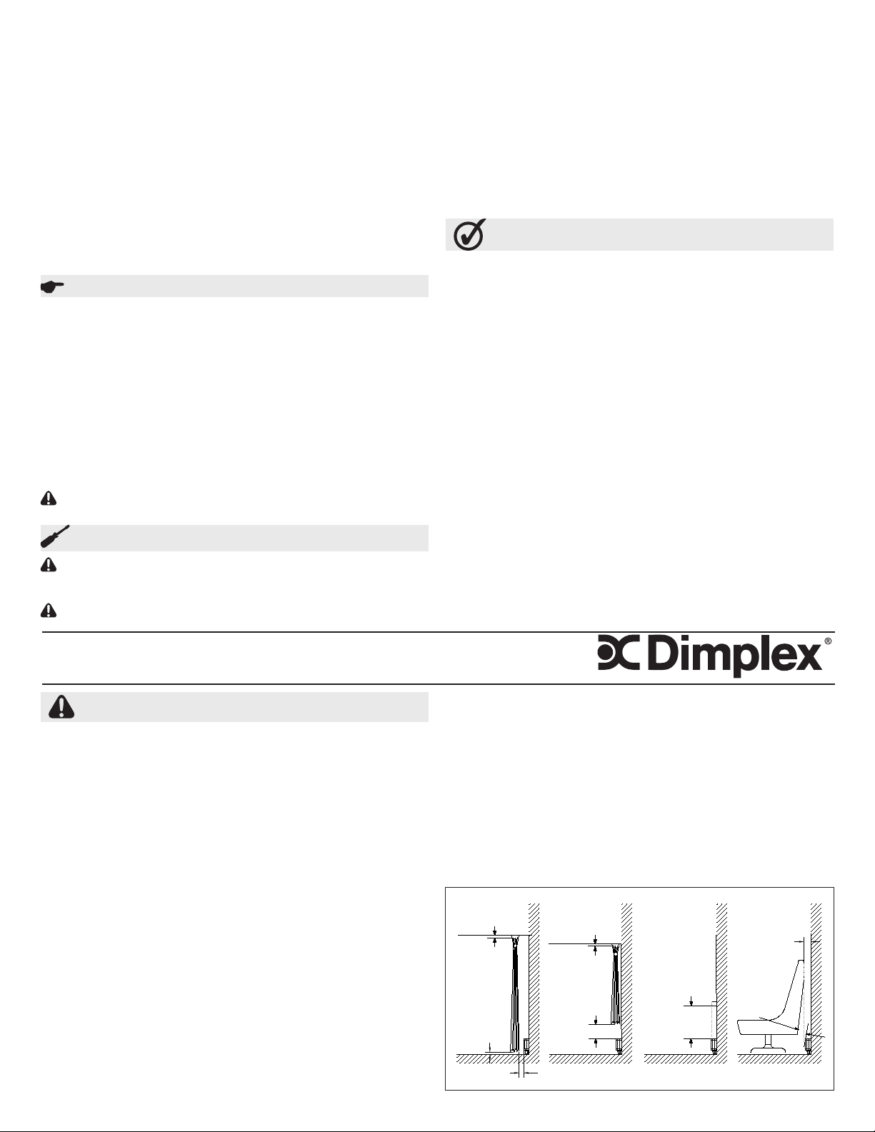
Figure 1
A B C D
Instructions d’installation
3
EMPLACEMENT DU Plinthe-convecteur linéaire
Les plinthe-convecteurs linéaires sont des appareils de chauffage
hautement performants conçus pour fonctionner à des températures
supérieures à celles des plinthes chauffantes ordinaires. Ils peuvent
être montés directement sur placoplâtre, le plâtre, le bois ou les murs
en béton. En raison des températures élevées émises par le convec-
teur, la surface du mur peut atteindre des températures de 160ºF
(71 ºC) ou plus et certains matériaux pourraient se décolorer ou se
déformer (ex.: vinyle ou plastique). Dans ces situations, le convecteur
peut être espacé du mur et du plancher an de réduire l’exposition
des matériaux à ces températures. En installant le convecteur avec le
kit de Optimisateur d’installation, la température émise par l’appareil
peut être réduite à 129º F (54º C).
!
NOTE: Si l’appareil est installé contre un mur de construction nou-
velle, s’assurer que tous les matériaux appliqués ont été entièrement
traités selon les instructions du fabricant avant de mettre l’appareil
en marche.
RECOMMANDATIONS POUR L’EMPLACEMENT DE
RIDEAUX ET DE MEUBLES À PROXIMITÉ DES PLINTHE-
CONVECTEURS LINÉAIRES (FIGURE 1)
!
NOTE: Les objets ou matériaux respectants les distances pres-
crites ci-dessous seront à l’épreuve de la décoloration ou de la
distorsion (étirement ou rétrécissement) lors d’une exposition
prolongée (1000h) à une température de 200F (93C).
Pour un fonctionnement optimal des appareils de chauffage et pour
minimiser leurs effets sur les rideaux, les meubles et les objets à
proximité, observer les recommandations suivantes:
1. Rideaux longs: Accrocher les rideaux de manière à ce qu’il y ait
un espace d’au moins 1,5 po (3,8 cm) entre le haut des rideaux et
le plafond, d’au moins 1,5 po (3,8 cm) entre le bas des rideaux et
le revêtement du plancher (comme une moquette) ET d’au moins
3 po (7,6 cm) entre la surface verticale frontale de l’appareil et le
pli de rideau le plus près (rideaux ouverts). (Figure 1A)
2. Rideaux courts: Accrocher les rideaux de manière à ce qu’il y ait
un espace d’au moins 1,5 po (3,8 cm) entre le haut des rideaux et
le plafond et d’au moins 6 po (15,3 cm), préférablement davantage,
entre le bas des rideaux et la surface horizontale supérieure de
l’appareil. (Figure 1B)
3. Meubles: La distance entre les meubles et le devant du Plinthe-
convecteur linéaire ne doit pas être inférieure à 3 po (7,62 cm).
(Figure 1D)
4. Objets solides suspendus (à l’exception du plastique): Posi-
tionner le plinthe-convecteur linéaire de manière à ce qu’il y ait un
espace d’au moins 14 po (35,6 cm) entre le haut de l’appareil et
tout objet solide susceptible d’obstruer ou de dévier le débit d’air
vertical au haut de l’appareil. (Figure 1C)
5. Objets en plastique suspendus: Tous les objets en plastique ne
pouvant pas supporter longtemps des températures de 140 ºF (60
ºC) ou plus doivent être installés à au moins 20 po (50,8 cm) de
l’appareil. (Figure 1C)
!
NOTE: Si 2 plinthe-convecteurs linéaires sont installés près d’un
même angle mural, s’assurer qu’elles sont placées à au moins 6 po
(15,3 cm) de l’angle.
CÂBLAGE DU PLINTHE-CONVECTEUR LINÉAIRE INSTALLÉ
EN USINE
Toutes les plinthe-convecteurs linéaires comportent des connexions
à chacune de leurs extrémités. Les ls à chaque extrémité ont été
raccordés en usine à l’aide de capuchons de connexion en tant que
circuit fermé. Le circuit peut être ouvert à partir de l’un ou l’autre
des capuchons de connexion de façon à établir des raccords avec la
source d’alimentation et/ou les contrôles désirés. (Voir les schémas
de câblage.)
CONTRÔLES (non inclus)
Un thermostat (mural ou intégré) est requis pour le fonctionnement de
l’appareil. Contrôles Dimplex :
• Ensembles de thermostat intégré: DTK-SP, DTK-DP, DTKT-SP
ou DTKT-DP
• Thermostats muraux : TS521W, TD522W, HTC521W, HTC525W,
HTC621W ou HTC625W
• Relais à faible tension intégré : BLLVCxx ou BLLVD
INSTALLATION
AVERTISSEMENT: Couper la source d’alimentation avant l’ins-
tallation pour prévenir les chocs électriques.
1. Déballer et déposer le Plinthe-convecteur linéaire sur le sol, face
vers le haut (utiliser le matériau d’emballage pour protéger le plan-
cher au besoin). Retirer les couvercles avant.
!
NOTE: Retirer le couvercle central en libérant le haut d’abord.
!
NOTE: Les ailettes de l’appareil peuvent se plier facilement.
Pour obtenir un rendement optimal, s’assurer qu’elles restent à
la verticale.
2. Orienter l’appareil de la façon désirée et marquer l’emplacement de
trous pilotes - au haut et au bas à chaque extrémité, et au moins
un dans le milieu.
3. Installer le câblage selon les instructions des diagrammes de la
page 3 et des codes électrique national et local.
MISE EN GARDE: Brancher les appareils de chauffage à un
circuit de dérivation relié uniquement à des appareils de chauffage
dont l’installation est permanente et pourvu de dispositifs de pro-
tection contre les sur-intensités d’une valeur nominale ou réglée
inférieure ou égale à 30 ampères. La puissance raccordée totale
ne doit pas excéder 80 % de la tension nominale des dispositifs
de protection contre les sur-intensités. Il y a risque d’incendie si
l’appareil n’est pas installé ou entretenu conformément à ces ins-
tructions.
4. Positionner l’appareil en dissimulant les câbles dans le mur (ou
conduit), insérer des vis dans les trous pilotes présélectionné
ainsi que des séparateurs (le cas échant) à l’aide des chevilles
d’ancrage au besoin.
!
NOTE: Les vis ne doivent pas être fermement serrées; les
desserrer de 1/2 tour en prévision des effets d’expansion et de
contraction du boîtier et pour assurer un fonctionnement silencieux.
5. Remettre les couvercles en place sur l’appareil.
!
NOTE: Installer le couvercle frontal d’abord en commençant par
le haut, puis le bas.
CÂBLAGE DE PLUSIEURES PLINTHE-CONVECTEURS
LINÉAIRES ENSEMBLE
Les plinthe-convecteurs linéaires peuvent être câblées ensemble
en parallèle an d’être contrôlées par un même thermostat. Veuillez
vous assurer de la continuité de la mise à la terre lorsque les unités
sont câblés ensemble.
Utilisation
1. Cet appareil de chauffage électrique doit être installé correcte-
ment avant son utilisation.
2. Avant la mise en marche, enlevez toute la poussière liée à la
construction de l’intérieur et de l’extérieur de l’appareil (plâtre,
sciure, etc.).
Les appareils de chauffage Dimplex ont été conçus et testés pour un
fonctionnement sans problème. Tous les appareils de chauffage Dim-
plex sont munis d’une protection thermique intégrée an de prévenir
les surchauffes. Il est très important que l’air circule librement à trav-
ers l’appareil pour assurer son fonctionnement optimal. Lorsque la
circulation d’air est entravée, le dispositif la protection peut entraîner
l’arrêt et la mise en marche cycliques de l’appareil. Un appareil qui
fonctionne de façon cyclique ne pourra réchauffer la pièce de façon
adéquate.
MISE EN GARDE: Éviter tout contact direct entre l’appareil et le
papier, le tissu ou les meubles, pour éviter un incendie.
MISE EN GARDE: Avant de retirer le couvercle pour le nettoyage,
s’assurer que l’alimentation électrique a été coupée au panneau
électrique, pour prévenir les chocs électriques.
MISE EN GARDE: Pour éviter les brûlures, accorder à l’élément
et au boîtier sufsamment de temps pour refroidir avant de pro-
céder à l’entretien du Plinthe-convecteur linéaire.
Les appareils de la série LC ne contiennent aucune pièce mobile.
Comme l’appareil ne contient aucune pièce mobile, il exige peu d’en-
Entretien
n’incombent pas au fabricant, à l’exception des frais spéciquement couverts
par la garantie. Le mauvais usage ou la réparation de l’appareil par une
personne autre qu’un membre du personnel autorisé par le fabricant sans
l’autorisation écrite de ce dernier annulera la présente garantie.
La présente garantie remplace toute autre garantie ou condition, explicite ou
tacite, y compris, sans toutefois s’y limiter, les garanties de qualité mar-chande
ou de convenance à un usage particulier. De plus, la garantie constitue le seul
recours de l’acheteur et la seule responsabilité du fabricant en ce qui concerne
la vente de l’appareil, que ce soit pour une rupture de contrat, de garantie ou
de condition ou encore pour une inexécution fondamentale ou la rupture d’une
condition essentielle, pour négligence ou pour toute autre raison.
Le fabricant ne peut être tenu responsable de dommages particuliers, indirects
ou consécutifs ni de dommages résultant du retrait ou du remplacement d’un
Plinthe-convecteur linéaire faisant l’objet d’une réclamation sous garantie sans
l’autorisation du fabricant.
Cette garantie peut être transférée par l’acheteur initial du produit. Toute récla-
mation au titre de la présente garantie devra être soumise par écrit au directeur
du service à la clientèle à : Dimplex North America Limited, 1367 Industrial
Road, Cambridge, Ontario, N3H 4W3, Canada.
Zócalo convector lineal
Serie LC
Instrucciones de installación
INSTRUCCIONES IMPORTANTES
Cuando se utilizan aparatos eléctricos, siempre se deben tomar pre-
cauciones básicas a n de reducir los riesgos de incendios, descar-
gas eléctricas y lesiones a personas, incluyendo lo siguiente:
1. Lea todas las instrucciones antes de utilizar este zócalo convec-
tor lineal.
2. Los zócalo convectores lineales y los controles deberían ser
instalados por un contratista calicado. Los procedimientos para
el cableado y las conexiones deberían estar de acuerdo con el
código eléctrico nacional National Electric Code (CEC y NEC) y
con los códigos locales.
3. Un Zócalo convector lineal tiene en su interior piezas calientes
y que generan arcos o chispas. No lo utilice en áreas donde se
usen o almacenen gasolina, pintura o líquidos inamables.
4. Cuando se encuentra en uso, este Zócalo convector lineal está
caliente. Para evitar quemaduras, no permita que la piel expues-
ta entre en contacto con las supercies calientes. Mantenga los
materiales combustibles tales como: muebles, almohadas, ropa
de cama, papeles, ropa y cortinas alejados del Zócalo convector
lineal.
5. Para evitar posibles incendios, no bloquee en forma alguna las
tomas o descargas de aire. No lo utilice sobre supercies blandas
tales como una cama donde es posible que las aberturas queden
bloqueadas.
6. No inserte ni permita que ingresen objetos extraños en ninguna
abertura de ventilación o descarga, ya que esto puede causar
descargas eléctricas o incendio, o dañar el Zócalo convector lin-
eal.
7. No instale el calefactor contra supercies de tableros combust-
ibles de bra de celulosa de baja densidad, ni contra o debajo de
revestimientos de pared vinílicos.
8. No ubique estos zócalo convectores lineales debajo de ningún
receptáculo de tomacorriente eléctrico.
9. Verique los valores de la placa de identicación del Zócalo con-
vector lineal para asegurarse de que la tensión del zócalo con-
www.dimplex.com4
Le fabricant offre une garantie d’un an à compter de la date d’achat pour tout
vice de matériaux ou de fabrication du Plinthe-convecteur linéaire et de ses
composants, à l’exception des éléments qui sont garantis contre tout vice de
matériaux et de fabrication pour une période de dix ans. Dans le but de satisfaire
à toute demande liée à la garantie, le fabricant réparera ou remplacera sans
frais, en usine ou chez le client, à sa discrétion, toute pièce jugée défectueuse.
Les frais de transport et d’expédition liés à la réparation ou au remplacement
Garantie
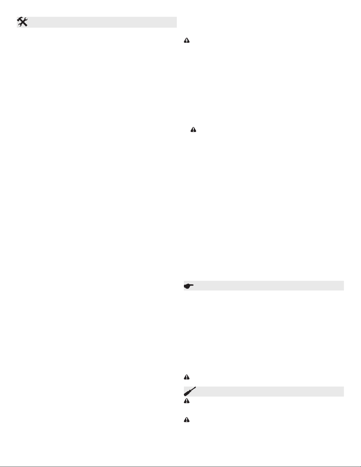
Figura 1
A B C D
Mínimo
1.5" (3,8 cm)
Mínimo
1.5" (3,8 cm)
Mínimo
1.5" (3,8cm)
Mínimo
3" (7,6 cm)
Mínimo
3" (7,6 cm)
Mínimo
3" (7,6 cm)
Mínimo
6" (15,3 cm)
Mínimo
Véase el punto 4 y 5
para la dimensión
UBICACIÓN DEL ZÓCALO CONVECTOR LINEAL
Los zócalo convectores lineales son calefactores de alto rendimiento
diseñados para funcionar a temperaturas de salida mayores que los
calefactores de zócalo convencionales. Se puede montar directamente
en un muro, yeso, madera o paredes de hormigón. Debido a la tem-
peratura de salida más alta, la supercie de la pared puede alcanzar
temperaturas de 160 º F (71 º C) o superior y algunos materiales pue-
den decolorar o deformar a estas temperaturas, por ejemplo, vinilo o
plástico. En estos casos el calefactor se puede montar a una distancia
de separación de la pared y del piso a n de reducir la temperatura
que se aplica a estos materiales. Al instalar el kit de calefacción con
la Optimizador de Instalacón, la temperatura emitida por el dispositivo
se puede reducir a 129º F (45º C).
!
NOTA: Si se está instalando la unidad en una pared recientemente
construida, asegúrese de que todos los productos que se hayan aplica-
do se hayan curado completamente de acuerdo con las instrucciones
del fabricante, antes de poner la unidad en funcionamiento.
RECOMENDACIONES PARA UBICAR CORTINAS Y
MUEBLES CERCA DE LOS ZÓCALO CONVECTORES
LINEALES (FIGURA 1)
!
NOTA: Los objetos o materiales que se encuentran dentro de las
distancias se indica a continuación no deben decolorar, ni distorsionar
dimensionalmente (ampliar o reducir) la exposición prolongada (hasta
1000 hrs.) a temperaturas de 200º F (93º C).
Para un funcionamiento más satisfactorio de los calefactores, y un
mínimo efecto sobre cortinas, muebles y objetos muy cercanos, se
deberían seguir las siguientes recomendaciones:
1. Cortinas de longitud completa: Cuelgue las cortinas de manera
tal que haya al menos 1,5 pulg. (3,8 cm) entre la parte superior
de las mismas y el cielo raso; al menos 1,5 pulg. (3,8 cm) entre la
parte inferior de las cortinas y el revestimiento de piso terminado (tal
como una moqueta, en caso de utilizarse); Y ADEMÁS al menos 3
pulg. (7,6 cm) entre la supercie vertical del frente del calefactor y
el pliegue más cercano de las cortinas (cortina abierta). (Figura 1A)
2. Cortinas de menor longitud: Cuelgue las cortinas de manera tal
que haya al menos 1,5 pulg. (3,8 cm) entre la parte superior de
las mismas y el cielo raso, y al menos 6 pulg. (15,3 cm), preferen-
temente más, entre la parte inferior de las cortinas y la supercie
horizontal superior del calefactor. (Figura 1B)
tretien au-delà d’un nettoyage à l’aspirateur. Toutefois, il est essen-
tiel de ne pas faire fonctionner le Plinthe-convecteur linéaire si de la
poussière ou de la saleté s’est accumulée sur l’élément; l’accumu-
lation de chaleur pourrait causer des dommages. Pour cette raison,
le Plinthe-convecteur linéaire doit être inspecté régulièrement, selon
ses conditions d’utilisation, et au moins une fois par année. Une fois
le nettoyage terminé, refermer le couvercle et rétablir le courant.
!
NOTE: L’utilisateur peut effectuer le nettoyage SEULEMENT.
Toute autre tâche d’entretien doit être conée à du personnel qualié.
vector lineal sea la misma que la del suministro de servicio. (La
placa de identicación se encuentra ubicada bajo el lado derecho
del elemento calentador).
10. TEMPERATURAS ELEVADAS: Mantenga alejados del zócalo
convector lineal los cables eléctricos, muebles, cortinados o cual-
quier otro tipo de material bloqueante.
GUARDE ESTAS INSTRUCCIONES
5
Garantía
El fabricante garantiza el Zócalo convector lineal y los componentes del
producto que se adjunta contra cualquier defecto de materiales o fabricación
durante un período de un año a partir de la fecha de compra, con la excepción
de los elementos, que se garantizan libres de defectos de materiales y
fabricación durante diez años. Como satisfacción total de cualquier reclamo
bajo esta garantía, el fabricante reparará o reemplazará sin cargo, en su
fábrica o en campo a su entera elección, cualquier pieza que en su opinión
sea defectuosa.
El fabricante no será responsable de ningún costo de transporte y envío
en relación a dicha reparación o reemplazo, excepto como los asuma
especícamente. El mal uso de este producto, o las reparaciones efectuadas
por personas que no sean el personal autorizado del fabricante sin la
aprobación por escrito del fabricante, invalidarán la presente garantía.
Esta garantía es en lugar de toda otra garantía o condición, ya sea expresa o
implícita, incluyendo pero no limitado a aquellas de comerciabilidad o aptitud
para el propósito, y constituirá el único recurso del comprador y la única
responsabilidad del fabricante con respecto a la venta del producto, ya sea en
la naturaleza de incumplimiento o incumplimiento del término fundamental, o
de negligencia u otro.
El fabricante no será responsable por ningún daño especial, indirecto o
emergente, ni por ningún daño que sea consecuencia de la remoción o
reemplazo de un Zócalo convector lineal sujeto a reclamos de garantía sin la
autorización del fabricante.
Esta garantía es transferible por el comprador consumidor original del
producto. Todo reclamo bajo esta garantía se debe presentar por escrito
al Gerente de Servicio, Dimplex North America Ltd., 1367 Industrial Rd.,
Cambridge, Ontario N3H 4W3, Canadá.
PRECAUCIÓN: Antes de retirar la cubierta delantera para realizar
una limpieza, asegúrese de que el suministro de energía se haya
desconectado en el panel del disyuntor, para evitar descargas
eléctricas
PRECAUCIÓN: Para evitar quemaduras, permita que transcurra
un tiempo adecuado para que el elemento y la carcasa del cuerpo
se enfríen antes de intentar trabajar en el Zócalo convector lineal.
La serie LC no contiene piezas móviles. Debido a que el
electrodoméstico no contiene piezas móviles, se requiere poco
mantenimiento más allá de la limpieza con aspiradora. Sin embargo,
es esencial que el Zócalo convector lineal no se haga funcionar con
una acumulación de polvo o suciedad sobre el elemento, ya que
esto puede causar un incremento del calor y eventualmente daños.
Por este motivo el Zócalo convector lineal se debe inspeccionar con
regularidad, dependiendo de las condiciones, y al menos una vez al
año. Una vez que se haya completado la limpieza, vuelva a colocar
la cubierta delantera y restablezca el suministro de energía.
!
NOTA: El usuario puede llevar a cabo la limpieza SOLAMENTE.
Cualquier otra tarea de servicio debería ser realizada por personal
de servicio calicado.
Mantenimiento
1. Este Zócalo convector lineal debe instalarse correctamente
antes de utilizarlo.
2. Antes de energizarlo, quite toda la suciedad proveniente de la
construcción (yeso, aserrín, etc.) del interior y del exterior del
Zócalo convector lineal.
Los zócalo convectores lineales Dimplex están diseñados y
ensayados para tener un funcionamiento seguro y sin problemas.
Todos los zócalo convectores lineales Dimplex están protegidos
contra el recalentamiento por un corte térmico integrado. A n de
lograr el funcionamiento más eciente del Zócalo convector lineal, es
de suma importancia que el aire uya libremente a través del mismo.
Un ujo de aire restringido podría causar que el protector contra
sobrecargas térmicas haga alternar el Zócalo convector lineal entre
“ENCENDIDO y APAGADO” intermitentemente. Un Zócalo convector
lineal que se enciende y apaga intermitentemente no suministrará
suciente calor a la habitación.
PRECAUCIÓN: Evite el contacto directo del Zócalo convector
lineal con papel, tela o muebles, para evitar posibles incendios.
Funcionamiento
3. Muebles: No coloque muebles a menos de 3 pulg. (7,62 cm) de
distancia del frente del Zócalo convector lineal. (Figura 1D)
4. Objetos sólidos salientes (a excepción de plástico): Posicione el
Zócalo convector lineal de manera tal que haya al menos 14 pulg.
(35,6 cm) entre la parte superior del calefactor y cualquier objeto
sólido que obstruya o desvíe el ujo de aire vertical que sale de la
parte superior de la unidad. (Figura 1C)
5. Objetos plástico salientes: Todos los artículos de plástico que no
pueden soportar la exposición prolongada a temperaturas de 60
º C o superior debe mantenerse un mínimo de 20 “(50,8 cm) por
encima de la unidad. (Figura 1C)
!
NOTA: Cuando 2 zócalo convectores lineales se instalan cerca del
mismo rincón, asegúrese de que ambos estén a un mínimo de 6
pulg. (15,3 cm) de distancia del rincón.
CABLEADO DE FÁBRICA DEL ZÓCALO CONVECTOR LINEAL
Todos los zócalo convectores lineales tienen prevista la conexión a
cualquiera de los dos extremos del Zócalo convector lineal. Los tra-
mos de cable en ambos extremos están empalmados en fábrica con
empalmes para cable como un circuito cerrado. El circuito se puede
abrir en cualquiera de las dos conexiones de empalme para cable a
n de realizar las conexiones al suministro de energía y/o a los con-
troles que se deseen. (Vea los diagramas de cableado)
CONTROLES (no se incluyen)
Se requiere un control de termostato (montado sobre la pared o inte-
grado) para hacer funcionar esta unidad. Controles Dimplex típicos:
• Kits de termostato integrado: DTK-SP, DTK-DP, DTKT-SP o
DTKT-DP
• Termostatos con tensión de línea externa: TS521W, TD522W,
HTC521W, HTC525W, HTC621W o HTC625W
• Relé de baja tensión integrado: BLLVCxx o BLLVD
INSTALACIÓN
ADVERTENCIA: Desconecte el suministro de energía antes de
la instalación para evitar descargas eléctricas.
1. Coloque el Zócalo convector lineal en el piso mirando hacia arri-
ba. Si es necesario, utilice el embalaje para protegerlo. Retire las
portadas
!
NOTA: Quite la cubierta del centro, mediante la liberación de
la parte superior en primer lugar.
!
NOTA: Aletas de calentador doblado fácilmente. Para un ren-
dimiento óptimo asegurar que siguen siendo vertical.
2. Lugar de la unidad en la posición deseada y marque los agujeros
piloto - superior e inferior en ambos extremos y al menos un con-
junto en el medio.
3. Alambre de la unidad en forma de diagramas por la página 6 y los
códigos eléctricos nacionales y locales.
PRECAUCIÓN: Conecte los zócalo convectores lineales a un
circuito ramal que se utilice solamente para los zócalo convecto-
res lineales instalados en forma permanente, y que esté protegido
por dispositivos contra sobrecorriente clasicados para o con-
gurados en no más de 30 amperes. La carga total conectada no
debería ser más del 80% de la clasicación de los dispositivos
contra sobrecorriente. Esto puede causar un peligro de incendio
si no se instala y mantiene de acuerdo con estas instrucciones.
4. Posición de Zócalo convector lineal, llevando cable de nuevo en
la pared (o canal), ejecute los tornillos a través de pre-selecciona
dos los agujeros de montaje y espaciadores (si corresponde), con
anclas de pared apropiadas, si fuera necesario.
!
NOTA: El tornillo se debería aojar ½ vuelta con respecto a la
posición ajustada a n de permitir la libre dilatación y contracción
de la carcasa y asegurar un funcionamiento silencioso.
5. Reemplace las cubiertas de la unidad.
!
NOTA: Instale la cubierta del centro primer, mediante la insta-
lación de la parte superior, luego la parte inferior.
PARA CONECTAR VARIOS ZÓCALO CONVECTORES
LINEALES JUNTOS
Los zócalo convectores lineales se pueden conectar en paralelo ex-
tremo con extremo para formar una longitud continua de sección de
Zócalo convector lineal. Cuando las unidades se instalan extremo
con extremo, una los zócalo convectores lineales para asegurar la
continuidad de la conexión a tierra entre ellos.

L1
L2 or N
Line/Ligne
L1
L2 or N
Line/Ligne
Right Side Power Connection/ Connexion d’alimentation côté droit/
Conexión de suministro en el lado derecho
Left Side Power Connection/Connexion d’alimentation côté gauche/
Conexión de suministro en el lado Izqierdo
L1
L2 or N
Single Pole Thermostat/ Thermostat unipolaire/
Termostato de polo único
For right hand side connection use same logic. Pour la connexion du côté droit, la même
logique s’applique. Para la conexión en el lado derecho siga la misma lógica
L1
L2/N
Double Pole Thermostat/ thermostat bipolaire/
Termostato de dos polos
For Left hand side connection use same logic. Pour la connexion du côté gauche, la même
logique s’applique. Para la conexión en el lado izquierdo siga la misma lógica.
Load/Charge/Carga
!
NOTE: When control accessories are installed,
use wiring diagram supplied with the accessory.
Following are examples of wiring diagrams with
thermostat.
MISE EN GARDE: Ne pas contourner ou
désactiver la protection thermique du circuit.
MISE EN GARDE: S’assurer que les ls
électriques et les capuchons de connexion sont
fermement raccordés.
MISE EN GARDE: Mise à la terre requise.
Nameplate
Plaque signalétique
Placa de identicación
FACTORY WIRING / CÂBLAGE D’USINE / CABLEADO DE FÁBRICA
Wiring Instructions/ Instructions de Raccordement / Instrucciones para el Cableado
CAUTION: Do not bypass or eliminate
thermal cutout from the circuit.
CAUTION: Check tightness of all electrical
connections and wire nuts.
CAUTION: Grounding connection is required.
PRECAUCIÓN: No omita ni elimine del
circuito el corte térmico.
PRECAUCIÓN: Verique que todas las
conexiones eléctricas y los empalmes para cable
estén ajustados.
PRECAUCIÓN: Se requiere conexión a tierra.
Thermal cutout
Protection thermique
Corte térmico
Heating element
Élément chauffant
Elemento calentador
Wire nut connection
Capuchon de connexion
Conexión de empalme para cable
Ground
Mise à la terre
Tierra
Ground /Mise à la terre/
Tierra
Ground /Mise à la terre/
Tierra
!
NOTE: Pour installer les accessoires de
contrôle, consulter le schéma de câblage fourni avec
l’accessoire. Vous trouverez ci-dessous des exemples
de schémas de câblage avec thermostat.
!
NOTA: Cuando se instalen accesorios de
control, utilice el diagrama de cableado que se
suministra con el accesorio. A continuación hallará
ejemplos de diagramas de cableado con termostato.
Ground /Mise à la terre/ Tierra
Ground /Mise à la terre/ Tierra
1367 Industrial Road Cambridge ON Canada N3H 4W3
1-888-346-7539 www.dimplex.com
In keeping with our policy of continuous product improvement, we reserve the right to make changes without notice.
Conformément à notre politique visant à améliorer sans cesse nos produits, nous nous réservons le droit d’effectuer des modications sans préavis.
De acuerdo con nuestra política de continua mejora del producto, nos reservamos el derecho a realizar cambios sin previo aviso.
© 2016 Dimplex North America Limited