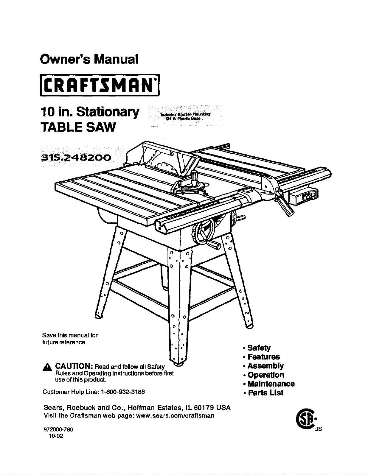
Owner's Manual
10 in. Stationary
TABLE SAW
Save this manual for
future reference
O
CAUTION: Read and follow all Safety
Rules and Operating Instructions before first
use of this product.
Customer Help Line: 1-800-932-3188
Sears, Roebuck and Co., Hoffman Estates, IL 60179 USA
Visit the Craftsman web page: www.sears.com/craftsman
972000-780
10-02
• Safety
• Features
• Assembly
• Operation
• Maintenance
• Parts List
FULL ONE YEAR WARRANTY ON CRAFTSMAN TABLE SAW
If this(RAFTSMAN Table Saw fails due to a defeat in matedal or workmanshipwithin one year from the date
of pumhase, Sears will repair it, free of charge.
Contacta Sears Service Canter for repair.
if this productis used for commercial or rental purposes,this warrantyapplies onlyfor 90 days from the date
ofpurchase.
Thiswarrantygivesyou specificlegalrights,and you may alsohaveotherdghtswhichvaryfromstateto
state.
Seare, Roebuck and Co., Dept. 8t7WA, Hoffman Estate,=,IL 60179
Yoursaw has manyfeatures for making cuttingoperations more pleasantend enjoyable. Safety, performance
and dependabilityhave been giventop priorityinthe designof this saw makingiteasy to maintainand operate,
CAUTION: Carefully read throughthisentire owner'smanual before usingyournew saw. Pay close
attentiontothe Rules ForSafe Operation, and all Safety Alert Symbols,includingDanger,Warning and
Caution. Ifyou use yoursaw propedyand onlyfor what itis intended,youwill enjoyyears of safe, reliable
service.
,_, Lookfor this symbol to point out important safetyprecautions,It means attention!!!Yoursafety is involved.
• k WARNING:
The operation of any powertool san resultin foreign objectsbeing thrown intoyoureyes,
whichcan result in severe eye damage, Beforebeginningpowertooloperation,always
wear safety gogglesor safetyglasseswithside shieldsand a fullface shieldwhen needed.
We recommend a WideVision Safety Maskfor usa over eyeglasses or standardsafety
glasses with side shields,availableat Sears Retail Stores.
• Warranty and Introduction............................................................................................................................. 2
• Table Of Contents ...................................................................................................................................... 2-3
• Rules ForSafe Operation........................................................................................................................... 4-6
• Electrical ....................................................................................................................................................... 7
• Glossary and ProductSpecifications............................................................................................................ 8
• Unpacking and Accassodes ......................................................................................................................... 9
• Loose Parts List.......................................................................................................................................... 10
• Small Parts List...................................................................................................................................... 11-12
• Tools Needed .............................................................................................................................................. 13
• Labels ..................................................................................................................................................... 14-15
• Features ................................................................................................................................................. 16-17
• Assembly................................................................................................................................................ 16-29
InstallingHandwhealson Table Sew Base ................................................................................................. 18
AssemblingLeg Stand ........................................................................................................................... 16-19
CRAFTSMAN"TABLESAW315.228390 2

MountingtheLegStandontheTableSawBase........................................................................................ 19
AssemblingTable Extensions..................................................................................................................... 20
AligningTable Extensions ..................................................................................................... 20
Installingthe Rear Rail................................................................................................................................ 21
Installingthe Front Rail ............................................................................................................................... 22
Aligning Rip Fence and Rails ...................................................................................................................... 23
Mountingthe Motor...................................................................................................................................... 23
Installing the Belt and Belt Guard ............................................................................................................... 24
Checkingthe Throat Plate........................................................................................................................... 24
Installingthe BladeGuard ........................................................................................................................... 25
Aligning the RivingKnifewiththe Blade ..................................................................................................... 26
Check Heeling (Paralleling)of the Saw Bladeto the Miter Gage Groove.................................................. 27
Checking RipFence and BladeAlignment .................................................................................................. 28
CheckingSquareness of ExtensionTables to Saw Table .......................................................................... 29
• Adjustments............................................................................................................................................ 30-34
Replacingthe Blade .................................................................................................................................... 30
Heeling (Paralleling)the Sawblade to Miter Gage Groove.................................................................... 31-32
Settingthe Bevel Stopsand Indicator.................................................................................................... 32-33
Adjustingthe Miter Gage ............................................................................................................................. 33
Removing/ Replacing the Throat Plate ...................................................................................................... 34
• BasicOperation of the Table Saw ......................................................................................................... 35-42
Causes of Kickback .................................................................................................................................... 35
Avoiding Kickback....................................................................................................................................... 35
CuttingAids................................................................................................................................................. 35
Types of Cuts .............................................................................................................................................. 36
Making a Cross Cut..................................................................................................................................... 37
Making a RipCut .................................................................................................................................... 37-38
Making a Miter Cut ...................................................................................................................................... 38
Making a Bevel Cross Cut ..................................................................................................................... 38-39
Making a Bevel Rip Cut ............................................................................................................................... 39
Making a Compound (Bevel) Miter Cut....................................................................................................... 40
Making a Large Panel Cut ........................................................................................................................... 41
Makinga Non-ThroughCUt ......................................................................................................................... 41
Makinga Dado Cut ...................................................................................................................................... 42
• Maintenance................................................................................................................................................ 43
• Lubrication................................................................................................................................................... 43
• Troubleshooting...................................................................................................................................... 44.46
• ExplodedView and Repair Parts List..................................................................................................... 48-65
• Parts Ordering/ Sen/ica ................................................................................................................ back page
3 cnn_lrxHnr TABLESAW31,5,228390
The purposeof safety symbolsisto attractyour attentionto possibledangers. The safety symbols,and the
explanationswiththem, deserve your carefulattentionand understanding,The safety warningsdo not by
themselves eliminateany danger. The instructionsorwarningsthey give are notsubstitutesfor properaccident
preventionmeasures.
SYMBOL MEANING
&
&
A
&
SAFETY ALERT SYMBOL
Indicates danger,warning,or caution. May beused in conjunctionwithother symbolsor
pictugraphs.
DANG ER: Failureto obey a safety warningwillresultinseriousinjurytoyourselfor toothers,
Always followthe safety precautionsto reducethe riskoffire,electdc shockand personalinjuP/,
WARNING: Failureto obey a safety warningcan resultin sadous Injury to yourselfor to others,
Always followthe safetyprecautionsto reducethe riskoffire,electdc shockand personal injuw.
CAUTION: Failureto obey a safety warningmay resultin propertydamage or personal injulyto
yourselforto others.Alwaysfollow the safety precautionsto reducethe dsk of fire,electricshock
and personal injury,
Note: Advisesyou of informationor Instructions vital tothe operationor maintenanceofthe equipment,
IMPORTANT
Servicingrequiresextreme care and knowledgeofthe
system and shouldbe performed onlybya qualified
servicetechnician, Forservicewe suggestyou return
the toolto yournearest Sears store or repaircenter.
Alwaysuse odginalfactory replacement partswhen
servicing.
_, WARNING: Do not attemptto operatethistool
untilyou have read thoroughlyand understand
completelyall instructions,safety rules,etc.
containedinthis manual. Failureto complycan
resultin accidentsinvolvingfire, electrical shock,
or serious personal injury.Save theowners
manualand reviewfrequentlyfor continuingsafe
operation,and instructingotherswho rneyusa
this tool.
READ ALL INSTRUCTIONS
• KNOW YOUR POWER TOOL. Read the owner's
manual carefully, Leam the saw's applications
and limitationsas well as the specificpotential
hazards related to this tool.
• DO NOT USE IN DANGEROUS ENVIRON-
MENT. Do not use power toolsnear gasoline or
other flammable liquids,in damp or wet loca-
tions, or expose them to rain. Keep the work
area well lit.
• MAKE WORKSHOP CHILD-PROOF with
padlocks and master switchesor by removing
starter keys.
• KEEP CHILDREN AND VISITORS AWAY. All
visitors sbou|dwear safety glasses and be kept
a safe distancefrom work area. Do not let
visitorscontact tool or extension cordwhile
operating.
• KEEP THE WORK AREA CLEAN. Cluttered
work areas and work benches inviteaccidents.
DO NOT leave toolsor pieces ofwood on the
saw while it is in operation,
• MAINTAIN TOOLS WITH CARE. Keep tools
sharpand clean for better and safer perfor-
mance. Follow instructionsfor lubricatingand
changing accessories,
• USE THE RIGHT TOOL FOR THE JOB. Do not
force the toolor attachmentto do a job it was
not designedfor. Usa it onlythe way it was
intended.
• DRESS PROPERLY. Do not wear loosecloth-
ing. gloves, neckties,rings, bracelets, or other
jewelry. They can get caught and draw you into
moving parts.Rubbergloves and nonslip
footwear are recommended.Also wear protec-
tive haircovedng to contain long hair.
• ALWAYS WEAR SAFETY GLASSES WITH
SIDE SHIELDS. Everyday eyeglasses have only
impact-rasistantlenses; they are NOT safety
glaseas.
• NEVER STAND ON TOOL, Serious injurycould
or.curifthe tool istipped or ifthe blade is
unintentionallycontacted.
EIIRFTIMRIr TABLESAW315.228390 4
RULES FOR SAFE OPERATION (Continued)
• DO NOT OVERREACH. Keep properfootingand
balance at all times.
• SECURE WORK. Usa clamps or • vise to hold
work when practical. It's safer then usingyour
handand frees bothhandsto operatetool.
• USE THE PROPER EXTENSION CORD. Make
sure yourextension cord is in good condition,
Use onlya cord heavy enoughto carry the
currentyour productwill drew,An undersized
cordwillcause a drop in linevoltage resultingin
loss of powerand overheating.A wire gage size
(A.W,G.) ofat least 14 is recommendedfor an
extension cord 25 feat or less in length.If in
doubt, usethe next heavier gage. The smaller
the gage number, the heavierthe cord.
• AVOID ACCIDENTAL STARTING. Be sure
switchis offwhen pluggingin,
• REMOVE WRENCHES AND ADJUSTING
KEYS, Get in the habitof checking- before
turning on tool - that hex keys and adjusting
wrenches are removedfrom tool.
CHECK DAMAGED PARTS. Beforeusingthe
tool again, check any damaged parts, including
guards,for properoperation and perfon_anca.
Check alignment of movingparts, bindingof
moving parts, breakage of parts, saw stability,
mountingand any other conditionsthat may
affect itsoperation.A damaged part muStbe
proparlyrepaired or replacedbya qualified
service technicianat a Sears Store or repair
center to avoid risk of personalinjury.
USE ONLY CORRECT BLADES. Use the dght
blade size, style and cuttingspeedfor the
matedal and the type of cut. Bladeteeth should
point downtoward the frontofthe table.
• USE RECOMMENDED ACCESSORIES. Using
improper accessories may risk injury.
USE ONLY SEARS REPLACEMENT PARTS.
All repairs, whether electrical or mechanical,
shouldbe made by a qualified sarvice technician
at a Sears Store or repair center.
• KEEP GUARDS IN PLACE and in goodworking
order, This includesthe bladeguard, dying
knife, and anti-ldckbackpawls.
• CHECK DIRECTION OF FEED. Feed work into
a blade orcutter against the direction of rotation
of the blade or cutter only.
DISCONNECT ALL TOOLS. When notin use,
before saP.'icing, or whenchanging attachments,
blades, bits,cutters, etc., all tools shouldbe
disconnectedfrom power supply.
• DO NOT FORCE THE TOOL. Itwill dothe job
better and more safelyat the rate for which it
was designed,
• NEVER LEAVE TOOL RUNNING UNAT-
TENDED. TURN THE POWER OFF. Do not
leave tool until itcomes to a complete Stop.
• BEFORE MOUNTING, DISCONNECTING OR
REMOUNTING THE MOTOR; unplugthe saw
and removethe switchkey.
A WARNING: When servicing,use only identical
Creflsman replacement parts. Use of any other
parts may create a hazard or cause product
damage.
• NEVER USE THIS TOOL IN AN EXPLOSNE
ATMOSPHERE. Normal sparkingofthe motor
could ignite fumes,
• MAKE SURE THE WORK AREA HAS AMPLE
LIGHTING to see the work and that no obStruc-
tions willinterferewith safe operation BEFORE
performingany work usingthis tool.
• DO NOT USE TOOL IF SWITCH DOES NOT
TURN n" ON AND OFF. Have defective
switches replaced by a qualified servicetechni-
cian at a Sears Store or repair center.
• GUARD AGAINST ELECTRICAL SHOCK by
preventingbodycontactwith grounded surfaces
such as pipes, radiators, ranges, refrigerator
enclosures.
• GROUND ALL TOOLS. See Electrical page.
• WEAR A DUST •ASK to keep from inhaling
fine particles.
• PROTECT YOUR HEARING. Wear hsaring
protectiondudngextended periodsof operation,
• DO NOT OPERATE THIS TOOL WHILE UN-
DER THE INFLUENCE OF DRUGS, ALCOHOL,
OR ANY MEDICATION.
• STAY ALERT AND EXERCISE CONTROL.
Watch whatyou ere doingand usecommon
sense. Do not operate tool when you are
tired. Do not rash.
• AVOID AWKWARD OPERATIONS AND HAND
PosmoNs where a sudden slipcouldcause
your handto move intothe blade. ALWAYS
make sure you have good balance.
• ALWAYS SUPPORT LARGE WORK PIECES
while cuttingto minimizerisk of blade pinching
and kickback.Saw may slip. walk or slidewhile
cutting largeor heavy boards.
• GUARD AGAINST KICKBACK, Kickbackcan
occurwhen the blade stalls,drivingthe work
piece beck towardthe operator. It can pullyour
hand intothe blade, resultingin sedous personal
injury.Stay out ofthe blade path and turnswitch
off immediatelyif blade bindsor stalls.
5 I;IIIIFI'ZNRN" TABLESAW315.228390
RULES FOR SAFE OPERATION (Continued)
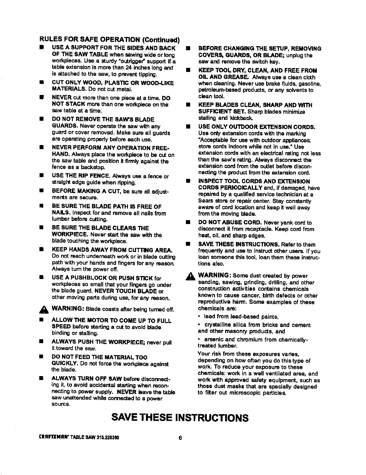
• USE A SUPPORT FOR THE SIDES AND BACK •
OF THE SAW TABLE when sawingwide or long
workpleoas. Usa e sturdy "outrigger"supportife
table extensionis more than 24 inches longand •
isattached to the saw, to preventtipping,
CUT ONLY WOOD, PLASTIC OR WOOD-LIKE
MATERIALS. Do not cut metal.
NEVER cut more then one piece at a time. DO
NOT STACK more than one workpieceon the
saw table at a time,
DO NOT REMOVE THE SAW'S BLADE
GUARDS. Never operate the saw with any
guard or cover removed, Make sure all guards
are operating propedybefore each use,
NEVER PERFORM ANY OPERATION FREE-
HAND. Always place the workplaceto be cut on
the saw table and positionitfirmlyagainstthe
fence as a backstop.
USE THE RIP FENCE. Always usa a fence or
straight edge guide when ripping,
BEFORE MAKING A CUT, be sure all adjust-
ments are secure.
BE SURE THE BLADE PATH • FREE OF
NAILS. Inspect for and remove all nailsfrom
lumber before cutting.
• BE SURE THE BLADE CLEARS THE
WORKPIECE, Never startthe saw with the
blade touching the workplace,
• KEEP HANDS AWAY FRO• CUTTING AREA.
Do not reach underneath work or in blade cutting
path withyour handsand fingers for any reason.
Alwaysturn the power off,
USE A PUSHBLOCK OR PUSH STICK for
workpiecas so small that yourfingers go under
the blade guard. NEVER TOUCH BLADE or
other moving parts dudngusa, for any reason,
_lb WARNING: Blade coastsafter balngturned off.
• ALLOW THE MOTOR TO COME UP TO FULL
SPEED before startinga out to avoid blade
bindingor stalling.
• ALWAYS PUSH THE WORKPIEGE; never pull
ittoward the saw.
• DO NOT FEED THE MATERIAL TOO
QUICKLY, Do not force the workplace against
the blade.
• ALWAYS TURN OFF SAW before disconnect-
ing it, to avoidaccidental =talting when recon-
nectingto power supply. NEVER leavethe table
saw unattendedwhileconnectedto a power
source.
BEFORE CHANGING THE SETUP, REMOVING
COVERS, GUARDS, OR BLADE; unplugthe
saw end remove the switchkey.
KEEP TOOL DRY, CLEAN, AND FREE FROM
OIL AND GREASE. Always use a clean cloth
when Cleaning.Never use brake fluids,gesaline,
petroleum-based products,or any solventsto
clean tool.
• KEEP BLADES CLEAN, SHARP AND WITH
SUFFICIENT SET. Sharp blades minimize
stallingand kickback,
• USE ONLY OUTDOOR EXTENSION CORDS,
Use onlyextensioncordswith the marking
"Acceptablefor usa with outdoor appliances;
store cordsindoorswhile not in usa." Use
extension cordswith an electrical rating not less
than the saw's rating,Always disconnectthe
extension cordfrom the outletbefore discon-
nectingthe productfrom the extension cord.
• INSPECT TOOL CORDS AND EXTENSION
CORDS PERIODICALLY and, if damaged, have
repairedby a qualifiedservicetechnicianat a
Sears store or repair center. Stay constantly
aware of cordlocationand keep it well away
fromthe moving blade.
IS DO NOT ABUSE CORD, Never yank cordto
disconnectit from receptacle. Keep cordfrom
heat, oil, and sharpedges.
• SAVE THESE INSTRUCTIONS. Refer tothem
frequentlyand use to instructother users, If you
loan someonethis tool, loanthem these instruc-
t_onsalso.
,&
WARNING: Some dust created by power
sanding, sawing, grinding, ddlling, and other
construction activities contains chemicals
known to cause cancer, birth defects or other
reproductive harm, Some examples of these
chemicals are:
• lead from lead-based paints,
• crystalline silica from bricks and cement
end other masonry products, and
, arsenic and chromium from chemically-
treated lumbar,
Your dskfrom these exposures vades,
depending on how often you do this type of
work. To reduce your exposure to these
chemicals: work in a well ventilated area, and
work with approved safety equipment, such as
those dust masks that are specially designed
to filter out microscopic particles.
SAVE THESE INSTRUCTIONS
[IIRFIrSI4RN"TABLESAW$I_228390 6
EXTENSION CORDS
Use only3-wirs extensioncordsthat have 3-prong
groundingplugsand 3-pole receptaclesthat accept
the tool'splug.When usinga powertool at a consid-
erable distancefrom the power source, usean
extensioncord heavyenoughto carrythe currentthat
thetool willdraw. An undersizedextensioncordwill
cause a dropin linevoltage, resultingina lossof
power and causingthe motortooverheat, Use the
chart providedbelowto determinethe minimumwire
size requiredin an extensioncord. Only roundjack-
eted cordslistedby Underwriter'sLaboratories(UL)
shouldbe used,
Length of Extension Cord Wire Size (A.W.G.)
Up to 25 feet 14
26-100 feet 12
When workingwiththe tool outdoors,use an exten-
sioncordthat isdesignedfor outsideuse. Thisis
indicatedbythe lettersWA on the cord'sjacket.
Before usingan extensioncord, inspectitfor looseor
exposedwires and cut orwom insulation.
A_ CAUTION: Keep the cordaway from the cutting
arsa and positionthe cord sothat Itwill not be
caughton lumber,tools, or otherobjectsduring
cuttingoperations.
ELECTRICAL CONNECTION
Your Sears Craftsman Table Saw ispowered by a
precisionbuiltelectricmotor. It shouldbe connected
to a power supply that is 120 volts, 60 Hz, AC only
(normal household cun'ent). Do notoperatethis tool
on directcurrent (DC), A substantialvoltagedropwill
cause a loss of powerand the motorwilloverheat. If
the saw does not operatewhen pluggedintoan
outlet, doublecheckthe powersupply.
SPEED AND WIRING
The no-load speed of yourtable saw isapproximately
3,600 rpm.This speed isnotconstantand decreases
undera load or withlowervoltage. Forvoltage,the
wiringina shopisas importantas the motor's horse-
power rating.A lineintendedonlyfor lightscannot
probedycarry a power tool motor.Wire thatis heavy
enoughfor a shortdistancewill be too lightfor a
greeterdistance. A linethat can supportone power
toolmay not be able to supporttwo orthrae tools.
GROUNDING INSTRUCTIONS
In theevent of a malfunctionor breakdown,grounding
providese path ofleast resistancefor electriccurrent
to reducethe riskof electricshock.This tool is
equippedwithan electdccord having an equipment-
groundingconductorand a groundingplug.The plug
mustbe pluggedintoa matchingoutletthat is properly
installedand groundedin accordancewithall local
codes and ordinances.
Do not modifythe plugprovided.If itwillnot fitthe
outlet,havethe properoutletinstalledby a qualified
electrician,improperconnectionofthe equiprnent-
groundingconductorcan resultina riskof electric
shook.The conductor with insulationhavingan outer
surfacethatisgreen withor withoutyellow stripesis
the equipment-groundingconductor. If repairor
replacementofthe electriccordor plugis necessary,
do notconnectthe equipment-groundingconductor to
a live terminal.
Check with a qualifiedelectricianor service personnel
ifthe groundinginstructionsare net completely
understood,or ifin doubtas towhether the toolis
properlygrounded.
Repairor replacea damagedorwom cordimmedi-
ately.
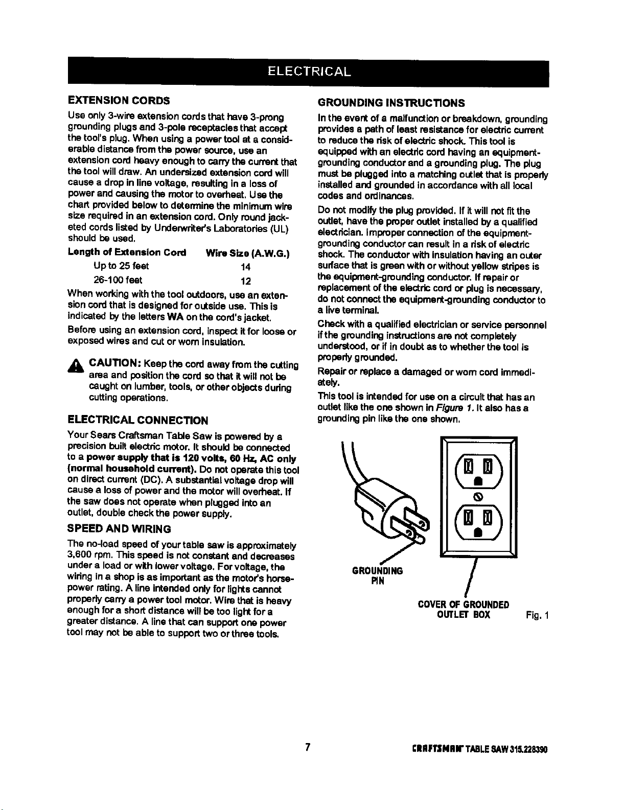
This toolis intendedfor use on a cimultthat hasan
outletlikethe one shownin Figure 1.It also has•
groundingpin likethe one shown,
\
GROUNDING
RN
/
COVEROFGROUNDED
OtRLEr BOX
Fig, 1
7 ClllF1'$Nlnr TABLESAW315,228390

Anti-Kickback Pawls
Toothedsafety devices behindthe blade designedto
stop a workpiece from being kickedback at the
operatorduringa ripping operation.
Arbor
The shaft on whicha blade or cuttingtool ismounted.
Bevel Cut
A cuttingoperation madewith the blade at any angle
otherthan 90° to the saw table.
Compound Cut
A cutwithboth a miterangle and a bevel angle.
Crosscut
A cuttingoperationmade acrossthe grainorthe width
of theworkpiece,
Dado
A non-throughcutthat gives a square notchor trough;
requiresa special blade.
Featherboard
A deviceto helpguide workpiecesduring ripcuts.
Freehand (for table saw)
Dangerouspracticeof making a cutwithoutusingrip
or miterfences. See Safety Rules.
Gum
A sticky,sap-based residuefromwood products.
Heel
Alignmentof the blade.
Kerr
The matedal removedbythe blade ina throughcutor
the slotproduced bythe blade In a non-throughcut.
Kickback
A hazardthat can occurwhen bladebinds or stalls,
throwingworkpleceback towardoperator.
Leading End
The end ofthe workpiece pushed intothe cuttingtool
first.
Miter Cut
A cuttingoperation made with the miter gage at any
angle otherthan 0°.
Molding
A non-through cutthat gives a varied shape to the
workpieceand requiresa special blade.
Push Stick
A device used to feed the workpiecethroughthe saw
blade dudngnarrowcuttingoperations.It helpskeep
the operator'shandswell away from the blade,
Rabbet
A notch in the edge of a workpiece.
Rw
A cutting operation to reduce the thickness of the
workpiece in order to make thinner pieces.
Resin
A sticky,sap-bssed substance.
RIp Cut
A cutmade withthe the grain ofthe workpiece.
SawbladiePath
The area directlyin linewith the blade-- over,under,
behind,or in frontof it. Also, the workpiecearea
whichwillbe or has been cutbythe blade.
Set
The distancethatthe tip ofthe saw bladetoothisbent
(or set) outwardfromthe face ofthe blade.
Throw-Back
Saw throwingback a workpiece;similarto kickback.
Through Sawing
Any cuttingoperation where the blade extends
completelythroughthe workpiece.
TratIIng End
The workpiece end last cutby the blade in a ripcut.
Workplace
The itemon whichthe cuttingoperation is beingdone.
The surfacesofa workpiesaare commonlyreferredto
as faces, ends, and edges.
Worktable
The surface on whichthe workpiece restswhile
performinga cuttingoperation.
BladeArbor 5/8 in,
BLadeDiameter 10 in.
Blade "13it O° - 45 °
TableSize withouttable extensions 20 in.x 27 in.
TableSize with table extensions 44 in.x 27 in.
Rating 13 Amperes, 1,5 HP
(3 HP max.developed)
Input 120 V, 60 Hz -AC only
No LoadSpeed 3,600 RPM
Cutting Capacity with Miter at 0°/Bevel 0° 3-3/8 in.
CuttingCapacity wIth Miter at 0°/Bevel 45°: 2-1/4 in.
£11RFTSMRN" TABLE ,SAW315.228390 8
Your new table saw has been designedto give you
many years of highquality performance.To insure
this goal, Woparcare andtreatment is important.
Careful treatment beginswith removingall partsfrom
the cartonand checkingthem againstthe listof loose
parts.The longbox containsthe rails.The large box
holdsall other parts,whichare detailed in the Loose
Parts List,
• Separate the saw and all partsfrom the packing
materialsand checkeach againstthe packinglist,
especiallythe smallparts thatcan be hiddeninthe
packing material.
Note: Do not discardthe packing matadals untilyou
havecarefullyinspectedthe sew, identifiedall
parts, and satisfactorilyoperated your newsaw.
WARNING: Never use gasoline,naptha, or
otherhighlyvolatile solvents.Do not ever let
brakefluids, gasoline, petroioumJoased
products,or penetrating oilscontact plasticparts.
Such chemicalscanweaken or destroyplastic.
• Removethe wax paper covedngon thetable. Use
anyordinaryhouseholdtypegrease and spot
remover. Immediatelyapply a coat of pastawax to
thetable and table extensions.
WARNING: To preventaccidental startingthat
couldcause possible sadous personalinjury,
assemble all parts toyour sew beforeconnecting
itto powersupply.Saw shouldnever be
connectedto power supplywhen you are
assemblingparts, makingadjustments,installing
or removingblades, or when notin use.
_1= WARNING: Ifany parts are missing,do not
operatethis tooluntilthe missingpartsare
replaced. Failuretodo socould resultin possible
seriouspersonalinjury.
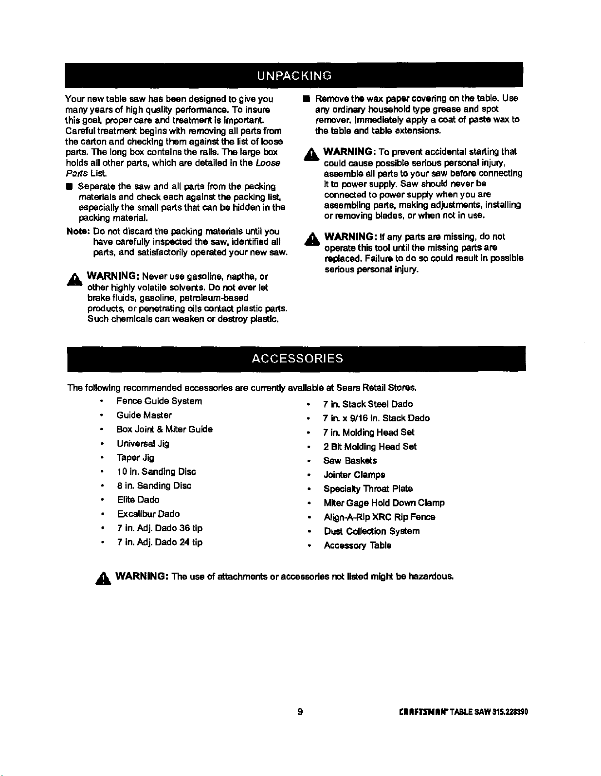
The followingrecommendedaccassodesare currentlyavailable at Sears RetailStores.
Fence Guide System
Guide Master
BoxJoint& MiterGuide
UniversalJig
TaperJig
10 in.Sanding Disc
8 in.Sanding Disc
Elite Dado
ExcaliburDado
7 in.Adj. Dado 36 tip
7 in.Adj. Dado 24 tip
7 in.Stack Steel Dado
7 in.x 9/t6 in, Stack Dado
7 in. MoldingHead Set
2 BitMoldingHead Set
Saw Baskets
JointerClamps
SpecialtyThroat Plate
MiterGage Hold DownClamp
Align.A-RipXRC RipFence
Dust CollectionSystem
Accessory Table
A_. WARNING: The useof attachmentsor accassedesnot listedmightbe hazardous.
9 ElUlIqrENIIN"TABLESAW31.5.2,?.8,_0
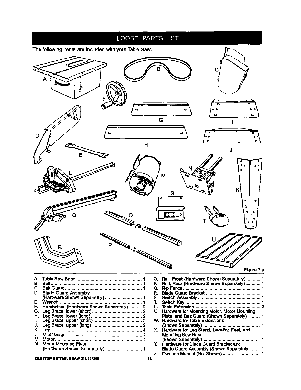
The following items are included with your Table Saw.
D
A
A. TableSaw Base ................................................... 1
B. Belt....................................................................... 1
C, BeltGuard............................................................ 1
D, Blade GuardAssembly
(Hardware ShownSeparately) ............................. 1
E, Wrench ................................................................ 1
F, Handwheel (Hardware ShownSeparately) .......... 2
G, Leg Brace, lower(short)....................................... 2
H, Leg Brace, lower(long)........................................ 2
I, Leg Brace, upper (short)...................................... 2
J. Leg Brace, upper (long) ....................................... 2
K. Leg ....................................................................... 4
L. Miter Gage ........................................................... 1
M. Motor.................................................................... 1
N. Motor MountingPlate
(Hardware Shown Separately) ............................. 1
CRnFTSMnN'TABLESAW315,228,390
O. Rail, Front (Hardware ShownSeparately) ........... 1
R Rail, Rear (Hardware ShownSeparately)............ 1
Q. Rip Fence............................................................. 1
R. Blade Guard Bracket........................................... 1
S. Switch Assembly................................................. 1
T. Switch Key........................................................... 1
U, TableExtension ................................................... 2
V, Hardware for MountingMotor,Motor Mounting
Plate, and BeltGuard (ShownSeparately) .......... 1
W. Hardware for TableExtensions
(ShownSeparately) ............................................. 1
X. Hardware for Leg Stand,LevelingFeet, and
MountingSaw Base
(Shown Separately) ............................................. 1
Y. Hardwarefor BladeGuard Bracketand
BladeGuardAssembly(ShownSeparately)........ 1
Z. Owner's Manual (Not Shown).............................. 1
10
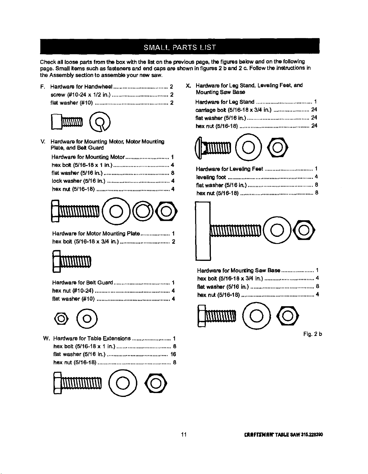
Checkallloosepartsfromtheboxwiththelistonthepreviouspage,thefiguresbelowandonthefollowing
page.Smallitems such as fasteners and end capsare shownin figures2 b and 2 c. Followthe instructionsin
the Assembly sectionto assemble your new sew.
F. Hardware for Handwheel................................... 2
screw (#10-24 x 1/2 in.) .................................... 2
flat washer (#10) ............................................... 2
V. Hardware for MountingMotor,Motor Mounting
Plate, and BeltGuard
Hardwarefor MountingMotor............................ 1
hex bolt (5116-18x 1 in.).................................... 4
flat washer (5/16 in.) .......................................... 8
lockwasher (5/16 in.) ........................................ 4
hex nut (5116-18) ............................................... 4
X. Hardwarefor Leg Stand, LevelingFeet, and
MountingSaw Base
Hardwarefor LagStand .................................... 1
carriage bolt (5/16-t8 x 3/4 in.) ....................... 24
fiatwasher (5/16 in.)........................................ 24
hex nut (5116-18) ............................................. 24
Hardwarefor LevelingFeet ............................... 1
levelingfoot ....................................................... 4
flatwasher (5/16 in.).......................................... 8
hex nut (5116-18) ............................................... 8
Hardware for Motor MountingPlate................... 1
hex bolt (5/16-18 x 3/4 in.)................................ 2
Hardware for Belt Guard.................................... 1
hex nut (#10-24) ................................................ 4
flat washer (#10) ............................................... 4
W, Hardware for Table Extensions ......................... 1
hex bolt (5/16-18 x 1 in.)................................... 8
flat washer (5/16 in.)....................................... 16
hex nut (5/16-18) ............................................... 8
i
m
Hardwarefor MountingSaw Base..................... 1
hex bolt (5116-18 x 3/4 in.) ................................ 4
fiat washer (5/16 in.) ......................................... 6
hex nut (5/16-18) ............................................... 4
Fig. 2 b
11 rlUIFTSNRIrTABLESAW315,228,190
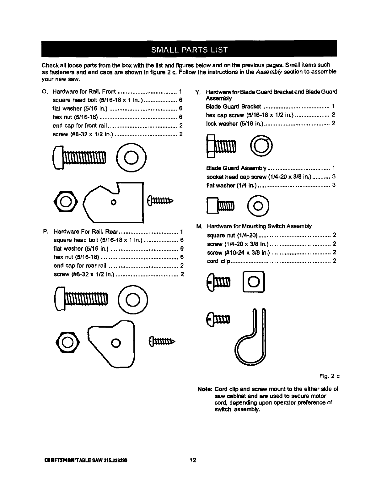
Checkalllooseparsfromtheboxwiththelistandfiguresbelowandonthepreviouspages.Smallitemssuch
asfasteners and end caps are shownin figure 2 c. Followthe instructionsin theAssembly section to assemble
your new sew.
O. Hardware for Rail, Front.................................... 1
square head holt (5/16-18 x 1 in..).................... 6
flat washer (5/16 in.) ......................................... 6
hex nut (5/16-18) ............................................... 6
end cap for front rail.......................................... 2
screw (#8-32 x 112in.) ...................................... 2
P, Hardware For Rail, Rear.................................... 1
square head bolt(5/16-18 x 1 in,)..................... 6
flat washer (5/16 in.) ......................................... 6
hex nut(5/16-18) ............................................... 6
end cap for rear rail........................................... 2
screw (#8-32 x 1/2 in.) ...................................... 2
Y*
i_
Hardwarefor BladeGuardBracketand BladeGuard
Assembly
Blade Guard Bracket......................................... 1
hex cap screw (5/16-18 x 112in.) ..................... 2
lock washer (5/16 in.)........................................ 2
BladeGuardAssembly...................................... 1
sockethead cap screw (1/4-20 x 318in.)........... 3
fiatwasher (1/4 in.)............................................ 3
Hardwarefor MountingSwitchAssembly
squara nut (1/4-20) ............................................ 2
screw(1/4-20 x 3/8 in.)..................................... 2
screw(#10-24 x 3/8 in.) .................................... 2
cord clip............................................................. 2
(
Fig. 2 c
Note: Cord clipand screw mountto the either side of
saw cabinet and are usedto secure motor
cord,dependinguponoperator preferancaof
switch assembly,
I:ll nFTJflNII N"I'ABLE SAW 315.228390 12
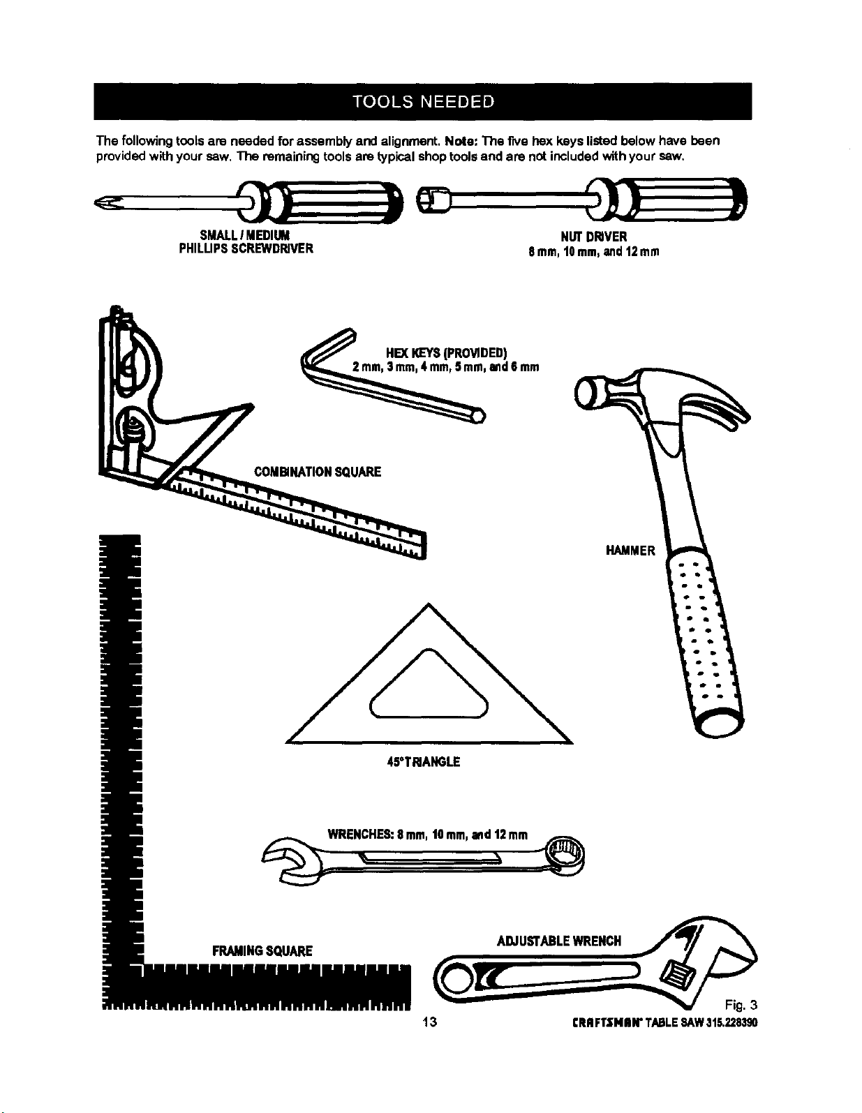
The following tools are needed for assembly and alignment, Note: The five hex keys listed below have been
provided with your saw. The remaining tools are typical shop tools and are not included with your saw.
SMALLI MEDIUM
PHILUPSSCREWDRIVER
NUTDRIVER
8ram,t0 mm,and12mm
HEXI_EYS(PROVIDED)
and6mm
COMBINATIONSQUARE
45°TRIANGLE
HAMMER
_WRE_HES: 8.m, ,Omm,and_2mm _¢_
FRAMINGSQUARE ADJUSTABLEWRENCH
13 CRRFTSNIIW TABLESAW315.228390
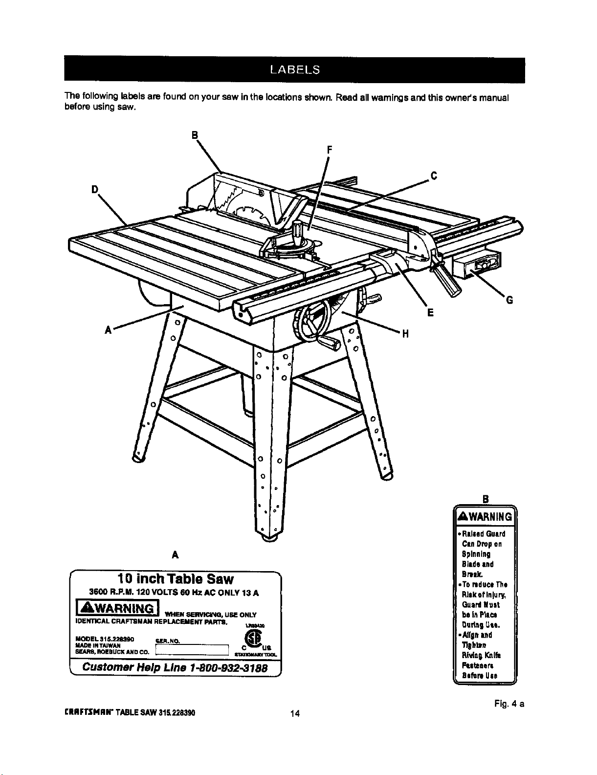
The following labelsare found onyour saw inthe locationsshown.Read allwarningsand this owner'smanual
beforeusingsaw.
B
D
E
H
A
10 inch Table Saw
3600 R.P.M. 1;!0 VOLTS 60 HZ AC ONLY 13 A
JAWARNING J,,....._--.. u. o._,
IDENTICAL CRAFTBMAN REPLACEMENT PARTS.
MODEL 315.228390 ra,lR.NO. C_
MADE INTAIWAN US
SF.ARS.ROEBUCI(ANDCO. I 1 S_I_.-lCaUUWI:=OI.
Customer Help Line 1-800.932.3188
B
AWARNING
Fig. 4 a
CRRFI"$NRN"TABLESAW315.228390 14

C
• D •
IDo Not Lift Saw With Rails 1
_or Extension Tables, J
F
A WARNING
• Attach Btade Guard
Assembly Before
Operating this Saw
• Read Owners
• G
E
WARNING
Debris on Pall can mlsallgn
the rip fence. Workplace
could bind or suddenly
kick back. You could be
hit or cut, Clean debris
off fence Pall before
3ositlonlng fence.
£RRFr$ H RN"FI:_-:z: .'i_-_-"____:_=.J
Fig. 4 b
15 CRRFTZNIIN"TABLE8/kW315.228,190
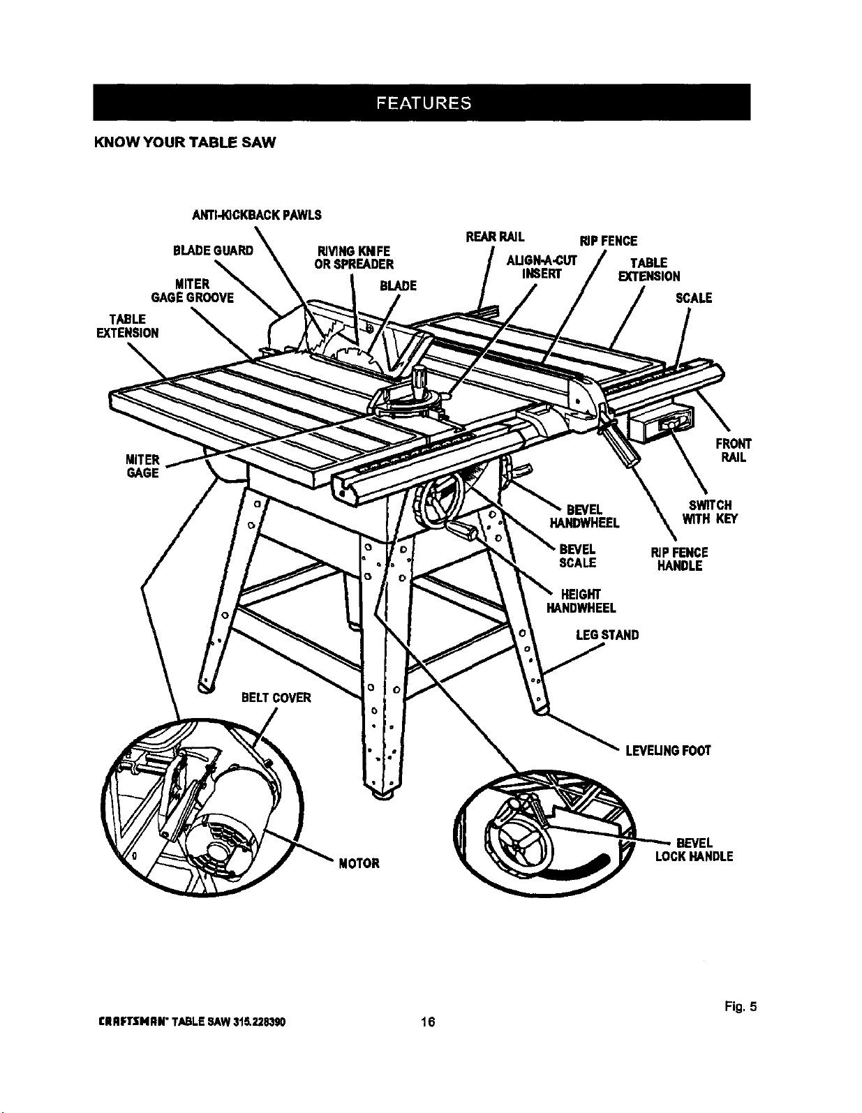
KNOW YOUR TABLE SAW
ANTI-KICKBACKPAWLS
MITER
GAGEGROOVE
TABLE
EXTENSION
RIVINGKNIFE
ORSPREADER
REARRAIL RiPFENCE
AUGH-A_UT TABLE
INSERT EXTENSION
BLADE
SCALE
MITER
GAGE
BELTCOVER
o
o
FRONT
RAIL
BEVEL SWITCH
HANDWHEEL WITH KEY
RIP FENCE
SCALE HANDLE
HEIGHT
HANDWHEEL
LEGSTAND
LEVEUNGFOOT
MOTOR
BEVEL
_CK_NDLE
Fig, 5
CRRFTSNRN"TABLESAW3t5,228390 16
OVERVIEW
The upperportionofthe blade projects upthroughthe
table, surroundedbyan insertcelledthe throatplate.
The heightofthe blade isset with a handwheaionthe
frontofthe cabinet. To accommodatewide panels,
thetabletop has extensionson each side.Detailed
instructionsare providedin the Operationsectionof
this manual for the basic cuts:cross cuts, mitercuts,
bevel cuts, and compoundcuts,
Forcutswiththe blade straight up and cuttingacross
the grain (crosscutsor miter cuts), usethe mitergage
toset the angle and pushthe woodintothe blade, To
cutwiththe blade straight up,alongthe grainof the
wood(ripcuts), usa the ripfence toguide the wood.
Push srnailerpieces with a puchblockorpushstick.
To tiltthe bladefor a bevelcut, usethe bevel
handwheelonthe sideof the cabinet.A bevel scale
on thefront ofthe cabinetshewsthe blade angle.
Insidethe ceblnet, adjustablepositivestops control
the degree oftilt.
Usathe miter gage with a bevel crosscut (compound
cut)and the ripfencewith a bevel dp cut. Other cuts
requirespedal attachments, which have detailed
instructionsto reduceriskof injuryand ensurethe
bastperformancefrom yournew saw,
Beforeattempting to useyoursaw, familiarizeyourself
withall operatingfeatures and safety requirementsof
yourSears Craftsmantable saw. The saw's features
are describedbelow,
ALIGN-A-CUT INSERT - A plasticinserton which
marksmay be madeto indicatethe locationofthe
sawcuton the workpieco,
ANTI-KICKBACK PAWLS - Kickbackisa hazard in
whichthe workpiece isthrownback towardthe
pper_or. The toothed pawls are designed tosnag the
workpiesetoprevent or reduce injuryshouldkickback
occur,
BEVEL HANDWHEEL - This handwheel, onthe right
side ofthe cabinet,tiltsthe blade for a bevel cut,
BEVEL SCALE - The easy-to-reed scale onthe front
of theworkstandshows the exact blade angle.
BLADE - This saw isprovidedwith a Craftsman64
tooth, 10 in. steel blade. The blade isadjusted with
bevel and height handwheelson the cabinet.Bevel
anglesare lockedwith a handle belowthefrontrail.
_k WARNING: Be sure to use onlyblades rated for
at least5,000 rpm and recommendedfor use on
this saw, Check with your nearestSears retail
store.
BLADE GUARD - Always keep the guard downover
theblade for through-sawingcuts.
BEVEL LOCK HANDLE - This handle,placed just
undertheworktable surfaceon the frontofthe cebi-
net, locksthe angle settingofthe blade. Be sure the
handleis hangingstraightdownbeforetiltingthe
blade. If it is notstraightdown, itmay jam and bend
the lockingbolt,
HEIGHT HANDWHEEL - Use this handwheelto lower
and raise theblade for adjustmentsor replacement,it
islocatedon the frontof the cabinet.
MITER GAGE oThis gage alignsthe woodfor a
crosscut.The easy-to-read indicatorshowsthe exact
anglefor a miter cut, with positivestops at 90° and
45 °.
MITER GAGE GROOVES - The miter gage rides in
these grooveson eitherside ofthe blade.
MITER GAGE KNOB - Locatedon the miter gage,
this knoblocksinthe cutting angleafter selection.
MOTOR (13 AMP) - The powerfulinductionmotoris
1.SHP (3HP maximumdeveloped), with capacitor
start and V-belt drive, and is housed ina sturdysteel
base,
RAILS - Frontand rear railsprovidesupportfor large
workplecesand the dpfence.
RIP FENCE - A sturdymetalfence guidesthe
workpleceand issecured withthe ripfence handle,
Groovesrunalongthe top and sides ofthe ripfence
for use withoptionaldamps and accessories,
RIP FENCE HANDLE - The handle onthe frontofthe
dp fence releasesthe ripfence or locksit inplace.
RIVING KNIFE OR SPREADER - Locateddirectly
behindtheblade, itkeeps cutedges from bindingand
supportsthe blade guard.
SCALE - Foundon the frontrail,the easy-to-read
scale providesprecisemeasurementsin ripcuts.
SWITCH WITH KEY - Yourtable saw has an easy
access powerswitch locatedbelowthe frontrail, The
yellowswitchkey mustbe removedfrom the hard-
ware bag and insertedintothe switch beforesaw can
be oper_ed. To lockthe switchinthe OFF position,
removethe switchkey fromthe switch.Place the key
ina locationthat is inaccessibleto children and others
not qualifiedto usethe tool.
TABLE EXTENSIONS - Removable stamped steel
extensions,12 in.by27 in,, suppor_largerwork-
pieces.
17 CRIIFTSNIIN"TABLESAW315.228390
Assemblyis bastdone inthe area where the saw willbe used.When you remove the table saw base, loose
parts,and hardware fromthe peckingmatarials, checkall itemswiththe loose parts listand drawing.Ifyou are
unsura aboutthe descdptionofany pert.refer tothe drawing. Ifany partsare missing,delay assemblinguntil
you have obtainedthe missingpert(s).
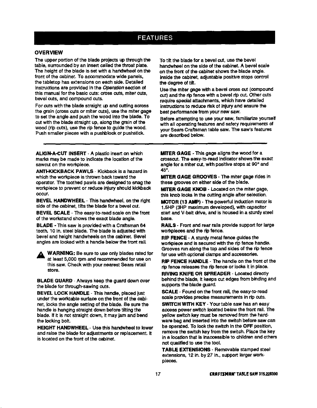
INSTALLING HANDWHEELS ON TABLE SAW
BASE
See Figure6.
• Each handwheel bag containsa handwheel, a
screw(#10-24 x 1/2 in.), and aflat washer (#10).
• Alignhendwheels tothe shaftendsthatextendfrom
thefrontand dghtsideofthetable sawbase, Match
theflat spotson theshaftand insidethehandwheal,
Inserta screwanda fiatwasher inthehandwheel
santer andtightenwith a 4 mm hexkey.
BEVEL
HANDWHEEL
HBGHT
HANDWHEEL
TABLE WASHER
SAWBASE SHAFTEND SCREW
Fig.6
Note: If you do not usethe leg standand mountthe
saw table base on a benchinstead of the legs,go
tothe procedureforAssambling Table Extensions.
Be surethe benchsurface has an openingfor
sawdust to fallthrough.The opening shouldbeas
largeas the opening inthe bottom of the saw table
base. A height of36 inchesfromthe top ofthe
sawtable tothe floor is recommended.
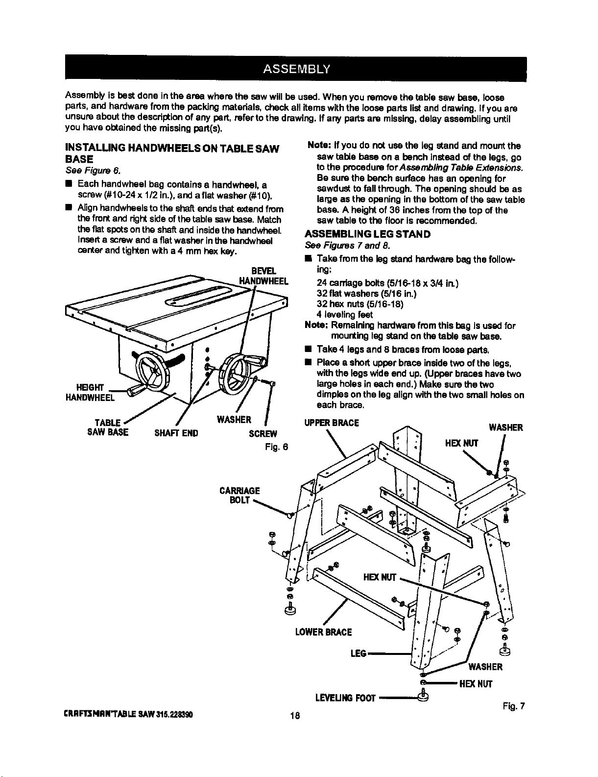
ASSEMBLING LEG STAND
See Figures 7 and 8.
• Take fromthe legstand hardwarebag thefollow-
ing:
24 cardagebolts (5/16-18 x 3/4 in.)
32 flat washers(5/16 in,)
32 hex nuts(5/16-18)
4 levelingfeet
Note: Remaininghardwarefromthis bag isused for
mountingleg standon thetable saw base.
• Take 4 legs and 8 bracesfrom looseperts.
• Place• shodupper brace insidetwo oftba legs,
withthe legswide end up. (Upper braces havetwo
largeholesin each end.) Make sure thetwo
dimpleson the lag alignwiththe two smallholeson
each brace,
UPPERBRACE
WASHER
HEXNUT
CARRIAGE
LOWERBRACE
LEG
HEXNUT
LEVEUNGFOOT
Fig. 7
£RRFlr];NRN"i'ABLESAW315,2211390 18
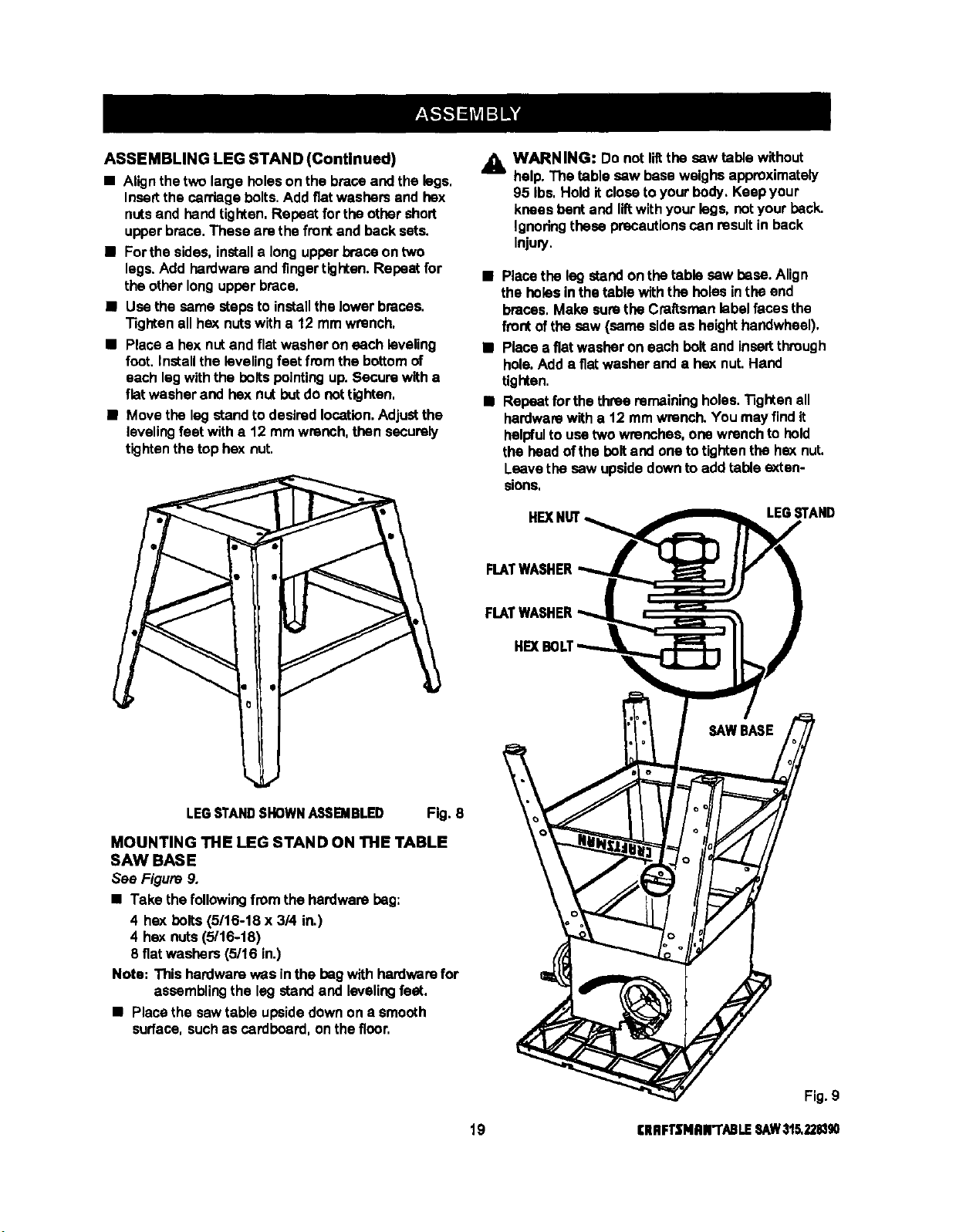
ASSEMBLINGLEGSTAND(Continued)
• Alignthe two large holeson the braceand the legs,
Insertthe carriagebolts,Addfiatwashers and hex
nutsand handtighten,Repeat for theother short
upperbrace,These are the frontand becksets.
• Forthe sides,installa long upperbrace on two
legs.Add hardwareand fingertighten.Repeat for
the otherlong upper brace.
• Use the same stepsto installthe lowerbraces,
Tightenall hex nutswith a 12 mm wrench,
• Place a hex nutand flatwasher on each leveling
foot,Installthe leveling feet fromthe bottomof
each leg withthe boltspointingup. Secure witha
flit washer and hex nut butdo nottighten,
• Move the leg standto desiredlocation.Adjustthe
levelingfeet witha 12 mmwrench, then securely
tightenthetop hex nut,
_. WARNING: Do not liltthe sew table without
help. The table saw baseweighsapproximately
95 Ibs. Hold itclosetoyour body. Keep your
kneesbent and liftwithyourlegs, not yourbeck.
Ignoringthese precautionscan resultin beck
Injury,
• Placethe leg standon thetable saw base. Align
the holesinthe table withthe holes inthe end
braces,Make surethe Craftsmanlibel faces the
frontofthe saw (same sideas heighthandwheel),
• Place a fiatwasher on each boltand insertthrough
hole.Adda fiatwasher and a hexnut.Hand
tighten.
• Repeatfor the three remainingholes. Tighten all
hardwarawith a t2 mm wrench.Youmay find it
helpfulto usetwo wrenches, one wrenchto hold
the head ofthe bolt and one totightenthe hex nut.
Leavethe sew upsidedownto add table exten-
sions,
LEGSTAND
FLATWASHER
HEX
LEGSTANDSHOWNA,.%qBIBLED Fig. 8
MOUNTING THE LEG STAND ON THE TABLE
SAW BASE
See Figure 9.
• Take the followingfromthe hardware bag:
4 hex bolts(5/16-18 x 3/4 in.)
4 hex nuts(5'16-18)
8 fiatwashers (5116in.)
Note: This herdwam was inthe beg with hardwarefor
assemblingthe leg standand levelingfeat.
• Placethe sawtable upsidedownon a smooth
surface,suchas cardboard, onthe floor,
19
SAWBASE
Fig.9
CRRFTSNNFI'ABLESAW315.221B90
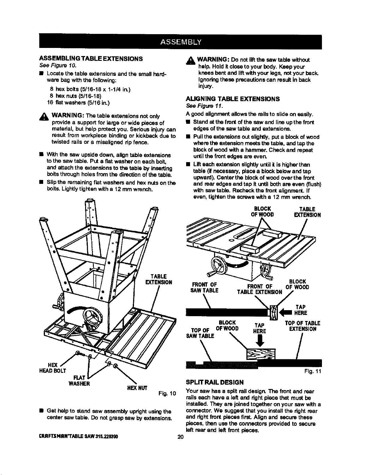
ASSEMBLINGTABLEEXTENSIONS
See Figure 10.
• Locate the table extensionsand the small herd-
ware bag withthe following:
8 hex bolts(5/16-18 x 1-1/4 in.)
8 hexnuts (5/16-18)
16 fiatwashers (5/16 in.)
,_k WARNING: The table extensionsnot only
providea supportfor kirge or wLdepieces of
material, but help protectyou. Serious injurycan
resultfrom workpieca bindingor kickback due to
twisted roils or a misalignedripfence.
• Withthe saw upside down, aligntable extensions
tothe saw table. PUta fiatwasher on each bolt,
and attachthe extensionstothe table by inserting
boilsthrough holesfromthe directionofthe table.
• Slipthe remainingflat washers and hex nutson the
bolts.Lightlytightenwith a 12 mm wrench.
j_ WARNING: Do notliftthe saw table without
help. Hold itclose toyour body, Keep your
knees bent and liftwithyour lags, notyourback.
Ignodngthese precautionscan result in back
injury.
ALIGNING TABLE EXTENSIONS
See Figure 11.
A good alignment allowsthe roilsto slideon easily.
• Stand at the front ofthe saw and lineupthe front
edges ofthe sew table and extensions.
• Pulltheextensionsoutslightly,put a blockofwood
wherethe extensionmeats thetable, and tapthe
blockofwoodwith a hemmer. Check and repeat
untilthefrontedges are even.
• Lifteach extensionslightlyuntilitishigherthan
table (if necessary,piaca a blockbelowand tap
upward).Centerthe blockofwood over the front
and rearedges and tap it until bothare even (flush)
with sew table. Recheck the frontalignment,If
even, tightenthe screwswith a 12 mm wrench,
BLOCK TABLE
OFWOOD EXTENSION
TABLE
EXTENSION
FRONT OF FRONT OF
SAWTABLE TABLE EXTENSION
\
BLOCK
OFWOOD
TAP
HERE
BLOCK TAP TOP OF TABLE
TOP OF OFWOOD HERE EXTENSION
SAW TABLE
HE)(
HEADBOLT
FLAT
WASHER
HEXNUT
Fig.10
• Get helpto stand saw assembly uprightusingthe
centersaw tabte, Do notgrasp saw by extensions.
rRRFTSNRN*'rABLESAW315.22s_Igo
SPLIT RAIL DESIGN
Your saw has a splitraildesign.The frontand rear
roilseach have a left and rightpiece that mustbe
installed.They are joinedtogether on your saw witha
connector.We suggestthat you installthe right roar
and rightfront piecesfirst. Alignand secure these
pieces,then usethe connectorsprovidedto secure
leftrear and left frontpieces,
20
Note: The right side of saw is on your dghtwhen
facingthe saw, as ifyou were in normal
operating position,
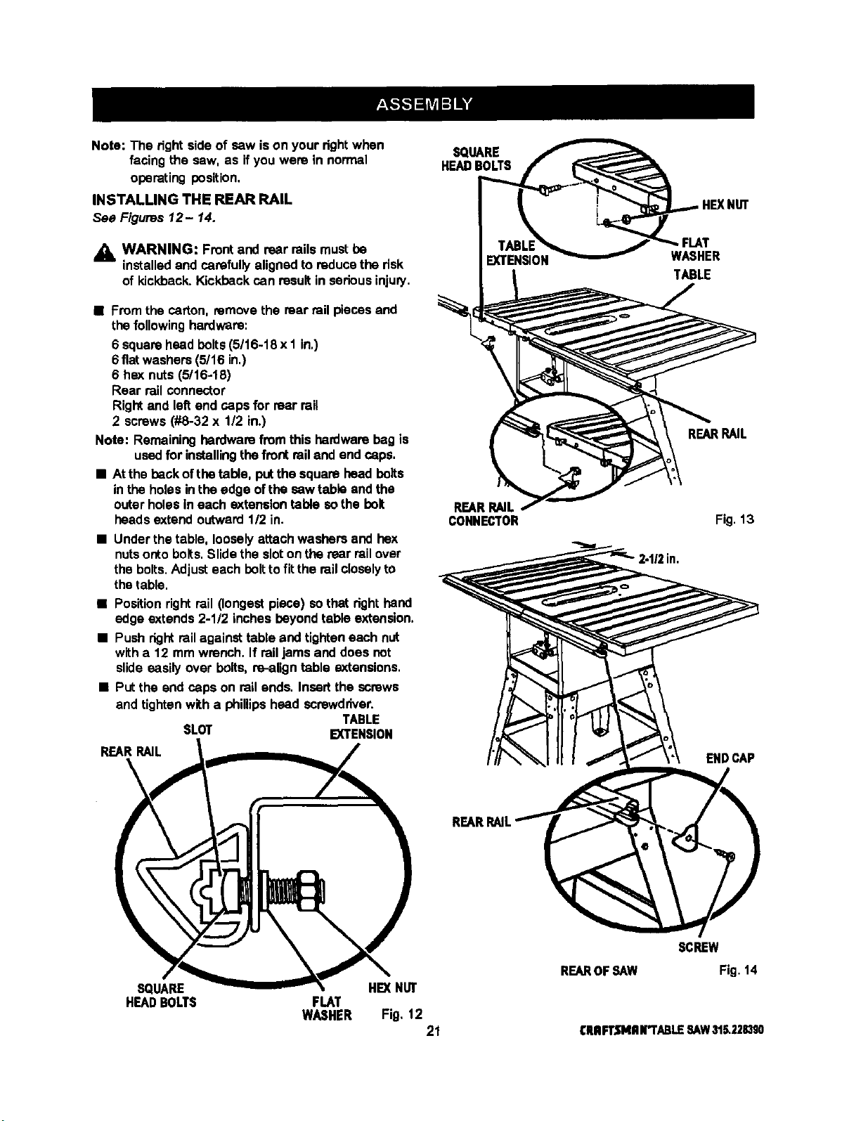
INSTALLING THE REAR RAIL
See Figures 12- 14.
_k WARNING: Frontand rear railsmustbe
installedand carefully alignedto reducethe risk
of kickback, Kickbackcan resultin serious injury.
• Fromthe carton, removethe mar railpieces and
the followinghardware:
6 squarehead bolts(5/16-18 x I in,)
6 fiatwashers(5/16 in,)
6 hex nuts (5/16-18)
Rear railconnector
Rightand leftend caps for rear rail
2 screws (#8-32 x 112in.)
Note: Remaininghardware from this hardware beg is
usedfor installingthe frontrailand end caps.
• At the back ofthe table, putthe squarehead bolts
inthe holesinthe edge ofthe saw table and the
outerholesin each extensiontable sothe bolt
heads extend outward112in.
• Under thetable, looselyattachwashers and hex
nutsontobolts.Slide the sloton therear railover
the bolts.Adjusteach bolt tofit the railcloselyto
thetable.
• Positionrightrail (longestpiece) sothat righthand
edge extends 2-1/2 inches beyondtable extension.
• Push rightrailagainsttable and tighteneach nut
with a 12 mm wrench. If railjams and does not
slide easily over bolts, re-aligntable extensions.
• Put the end caps on rail ends. Insertthe screws
and tighten witha phillipshead screwdriver.
TABLE
SLOT EXTENSION
REARRAIL
SQUARE
HEADBOLTS
REAR RAIL
CONNECTOR
WASHER
TABLE
REARRAIL
Fig. 13
ENDCAP
SQUARE HE)(NUT
HEADBOLTS FLAT
WASHER Fig, 12
21
SCREW
REAROFSAW Fig. 14
CRRFTSMRN'I"ABLESAW31_2283S0

INSTALLING THE FRONT RAIL
See Figures 15and 16.
• Get the front rail pieces,the switchassembly,and
thefollowing hardware:
6 square head bolts(5/16-18 x 1 in.)
6 flat washers (5/16 in.)
6 hex nuts(5/16-18)
2 screws(1/4-20 x 3/8 in.) (locatedon switch plate)
2 squarenuts (1/4-20) (located on switch plate)
Front railconnector
Rightand leftend caps for front rail
2 screws(#8-32 x 112in.)
• Set aside end capsand screwsuntilyou have
alignedthe ripfence and front rail.
• Insertthe s_ squarehead boltsintothetableand
extensions,sothe boltheadsextend outward112in.
• Looselyattach a washer and a hex nutto each
bolt.
• The backof the rail hastwo slots.Slide the upper
slot over the bolts. (Bottomslot isfor switch.)
• Alignthe dght rail from left to dght- Match the
7-1/8 in. mark on the right scale to the right
edge of the table saw base (main table). See
Figure 16.
• Snug rightrailagainsttable. Finger-tighteneach
nuton the table and extensions.
• Locate the switchassembly. The two screws are
installedthroughthe back of the switch platewith
the squarenutsextendingout towardthe front.
Note: The square nuts am looseon the switch plate.
• Slidethe square nutsintothe lowerslotofthe rail.
• Slide the switchassembly to a convenientposition,
leavingample clearancefor the hendwheel.
Tightensecurelywith a screwdriver.Do nottighten
the rail bolts.
• Attachthe and caps and screwswitha phillips
screwddver.
WARNING: Place the switchout ofthe
immediatework area to avoid accidentally
turningit off dudngoperation.
SAWTABLE TABLE
EXTENSION
SQUARE
HEADBOLTS
TABLE
EXTENSION
FRONT
CONNECTOR
FRONTRAIL
SCALE
RAILSLOT
FRONTRAIL
HEXNUT
FLAT
WASHER
Fig.15
ENDCAP
SCREW
TABLE
EXTEI_ON
SWITCHSLOT
RIGHTSCALE
ERRFTSMRN"i'ABLESAW315.22.8390
FRONTRAIL
WITHKEY
22
Fig. 16
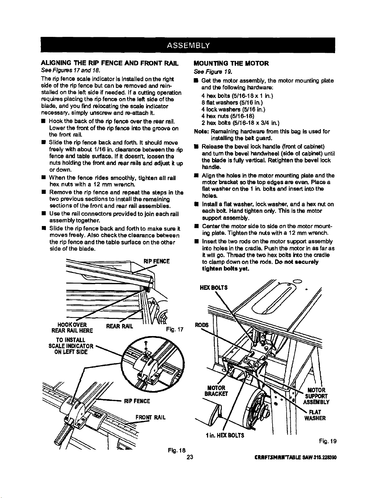
ALIGNINGTHERIPFENCEANDFRONTRAIL
See Figures17and 18.
The ripfence scaleindicatoris installedon the dght
side ofthe dp fence but can be removedand rein-
stalledon the leftside if needed. If a cuttingoperation
requiresplacingthe dp fence on the left sideofthe
blade, and you findrelocatingthe scale indicator
necessary,simplyunscrewand ra-attach it,
• Hookthe backof the ripfence over the rear rail.
Lowerthe frontofthe ripfence intothe grooveon
the front rail.
• Slidethe ripfence backand forth. It shouldmove
freely withabout t/16 in. clearance betweenthe rip
fence and table surface.If it doesn't, loosenthe
nuts holdingthe frontand rear railsand adjust itup
or down.
• When the fence ddas smoothly, tighten all rail
hex nuts with a 12 mm wrench.
• Remove the rip fence and repeat the steps in the
two previoussectionsto install the remaining
sectionsof the front and rear railassemblies.
• Use the railconnectors providedto join each rail
assembly togather.
• Slide the ripfence back and forth to make sure it
moves freely. Also check the clearance between
the ripfence and the table surface on the other
side ofthe blade.
HOOKOVER REARRAIL
REARRAILHERE
TOINSTALL
SCALEINDICATOR
ONLEFTSIDE
RIPFENCE
Fig. 17
MOUN_NGTHE MOTOR
See Figure 19.
• Get the motorassembly,the motormountingplate
and the following hardware:
4 hex bolts(5/16-18 x 1 in.)
8 fiatwashers (5/16 in.)
4 lockwashers (5/16 in.)
4 hex nuts (5/16-18)
2 hex bolts(5/16-t8 x3/4 in.)
Nota: Remaininghardwarefrom this bag is usedfor
installingthe belt guard.
• Release the bevel lockhandle(frontof cabinet)
and turnthebevel hendwheal (side of cabinet) until
the blade isfully vertical. Retightanthe bevel lock
handle.
• Alignthe holesin the motormountingplateand the
motorbracket sothe top edges are even. Place a
fiatwasher on the 1 in. belts and insertintothe
holes.
• Installa flat washer, Iockwasher, and a hexnut on
each bolt. Handtighten only.This isthe motor
supportassembly.
• Cantarthe motorsideto side on the motormount-
ingplate.Tightenthe nutswith a 12 mm wrench.
• Insertthe two rodson the motorsupportassembly
intoholes in the cradle. Push the motorinas far as
itwill go.Thraad the two hex boltsintothe cradle
to clamp downonthe rods. Do not securely
tighten bolts yet.
HE](BOLTS
RODS
RIPFENCE
MOTOR MOTOR
BRACKET
ASSB_BLY
FRONTRAIL
WASHER
I in. HE]( BOLTS
Fig. 19
Fig. 18
23 CRRFT.t'NRR'I'ABLESAW315.228390
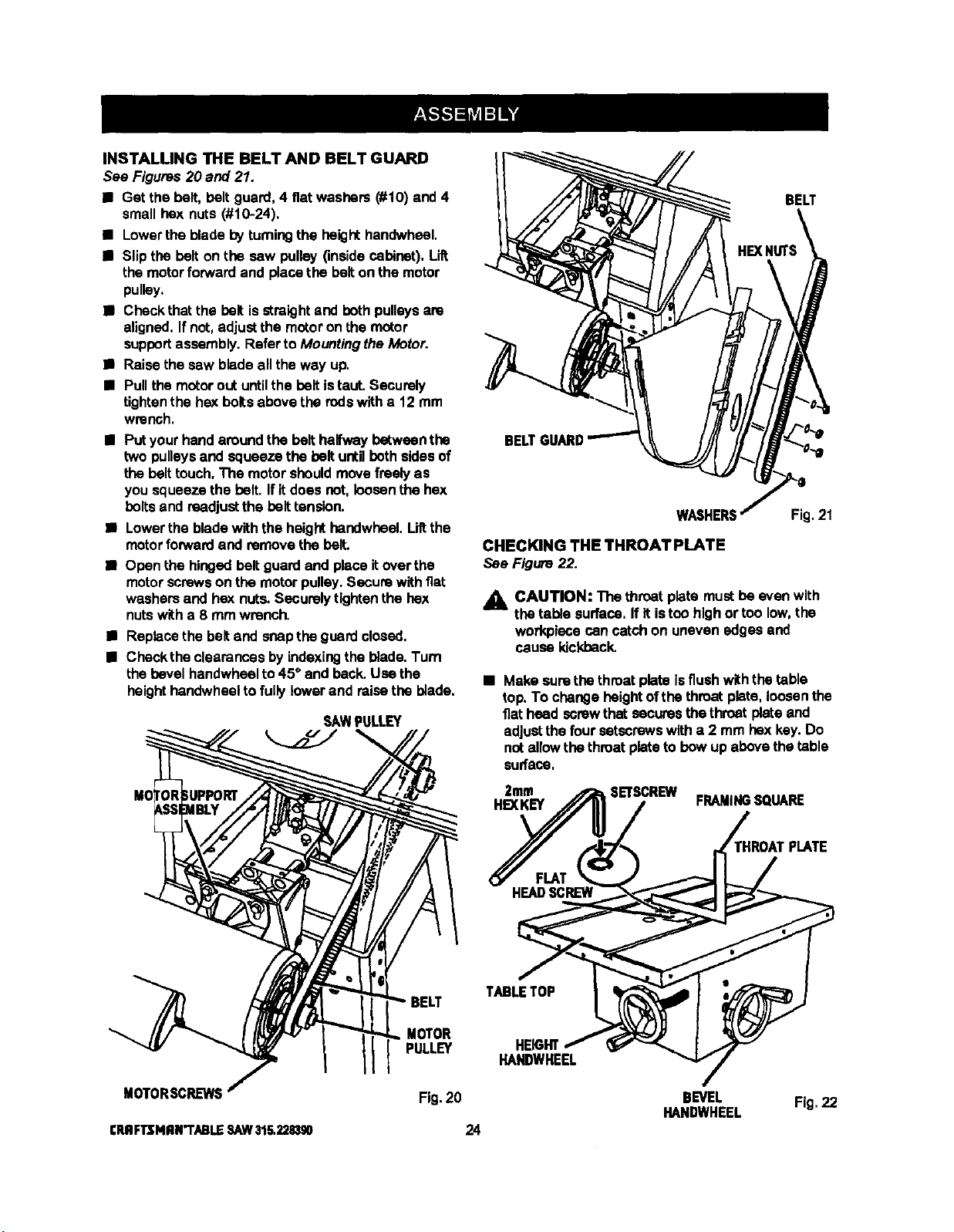
INSTALLING THE BELT AND BELT GUARD
See Figures20 and 21.
• Get the bolt,bolt guard, 4 fiatwashers (#10) and 4
small hex nuts (#10-24).
• Lowerthe blade byturningthe height handwheel,
• Slipthe bolt on the sew pulley (insidecabinet). Lift
the motorforwardand placethe bolt on the motor
pulley.
• Checkthat the bolt isstraightand bothpulleysare
aligned,If not,adjustthe motoron the motor
supportassembly. Referto Mountingthe Motor.
• Raise the sew blade allthe way up.
• Pullthe motorout untilthe beltistaut. Securely
tightenthe hex boltsabove the rodswitha 12 mm
wrench.
• Putyour handaroundthe bolt halfwaybetweenthe
two pulleys and squeeze the bolt untilbothsidesof
the belttouch.The motorshouldmovefreelyas
you squeezethe bolt. Ifitdoes not,loosenthe hex
bolts and readjustthe belttension.
• Lowerthe blade withthe height handwheel.Liltthe
motorforwardand removethe bolt.
• Open the hingedbolt guardand place itoverthe
motorscrewson the motorpulley.Secura withflat
washersand hex nuts.Securelytightenthe hex
nutswith a 8 mm wrench.
• Replacethe beltand snapthe guardclosed,
• Checkthe clearancesbyindexingthe blade.Turn
thebevel handwheelto 45* and back.Use the
heighthandwheeltofullylowerand raise the blade.
SAWPULLEY
BELT
BEL
WASHERS
CHECKING THE THROAT PLATE
See Figure22.
Fig.21
_1_ CAUTION: The throat plata mustbe evenwith
the table surface. If itistoo high ortoo low,the
workplacecan catchon uneven edges and
cause kickback.
• Make surethe throatplata isflushwiththe table
top.To changeheight ofthethroatplata, loosenthe
flatheed screwthat securesthe throatplate and
adjustthe foursetscrewswitha 2 mm hex key.Do
natallowthe throatplateto bow up abovethe table
surface.
2mm SETSCREW
HEXKEY FRAMINGSQUARE
HROATPLATE
TABLETOP
MOTORSCRL_NS
CRRFTJ;NRN"rABLESAW315.2,?.1BS0
MOTOR
PULLEY
Fig. 20
24
HEIGHT
HANDWHEEL
BEVEL
HANDWHEEL
Fig.22
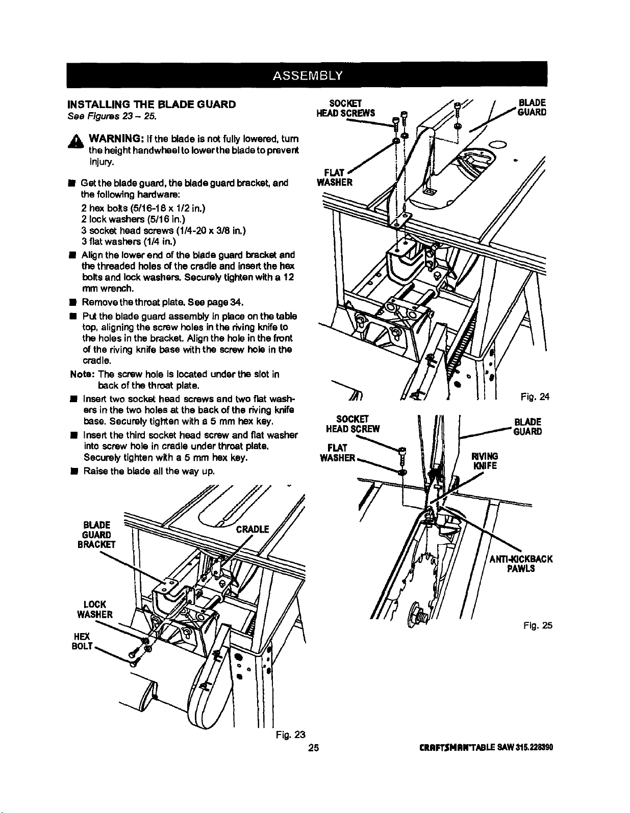
INSTALLINGTHEBLADEGUARD
See Figures23 - 25.
_L WARNING: Ifthe blade isnotfully lowered,turn
theheighthandwheeltolowerthe bladetoprevent
injury.
• Get thebladeguard,the blade guard bracket,and
the followinghardware:
2 hex bolts(5/16-18 x 1/2 in.)
2 lockwashers (5/16 in,)
3 sockethead screws (1/4-20 x 3/8 in.)
3 fiatwashers (1/4 in.)
• Alignthe lowerend ofthe blade guard bracketand
the threaded bolesof thecradleand insoltthe hex
boltsand lock washers.Securelytightenwitha 12
mmwrench.
• Remove thethroatplate,See page34.
• Putthe bladeguard assembly inplace on thetable
top,aligningthe screw holesinthe rivingknifeto
theholes inthe bracket.Alignthe holeinthefront
ofthe rivingknife base withthe screw holeinthe
cradle.
Note: The screwhole is locatedunderthe slotin
back ofthe throat plate.
• Inserttwo sockethead screwsand two flat wash-
erein the two holes at the backof the rivingknife
base, Securelytighten with a 5 mm hex key.
• Insmtthe third socket heed screwand fiat washer
intoscrew hole in cradle underthroat plate,
Securelytightenwith a 5 mm hex key.
• Raise the blade all the way up.
SOCI_ET
HEADSCREWS
FLAT
WASHER
SOCKET
HEADSCREW
FLAT
RIVING
KNIFE
BLADE
O
Fig. 24
BLADE
BLADE
GUARD
BRACKET
_NTI-KICKBACK
PAWLS
LOCK
WASHER
HEX
Fig. 25
Fig.23
25 CRAFTSNRr'I'ABLESAW315,2283g0
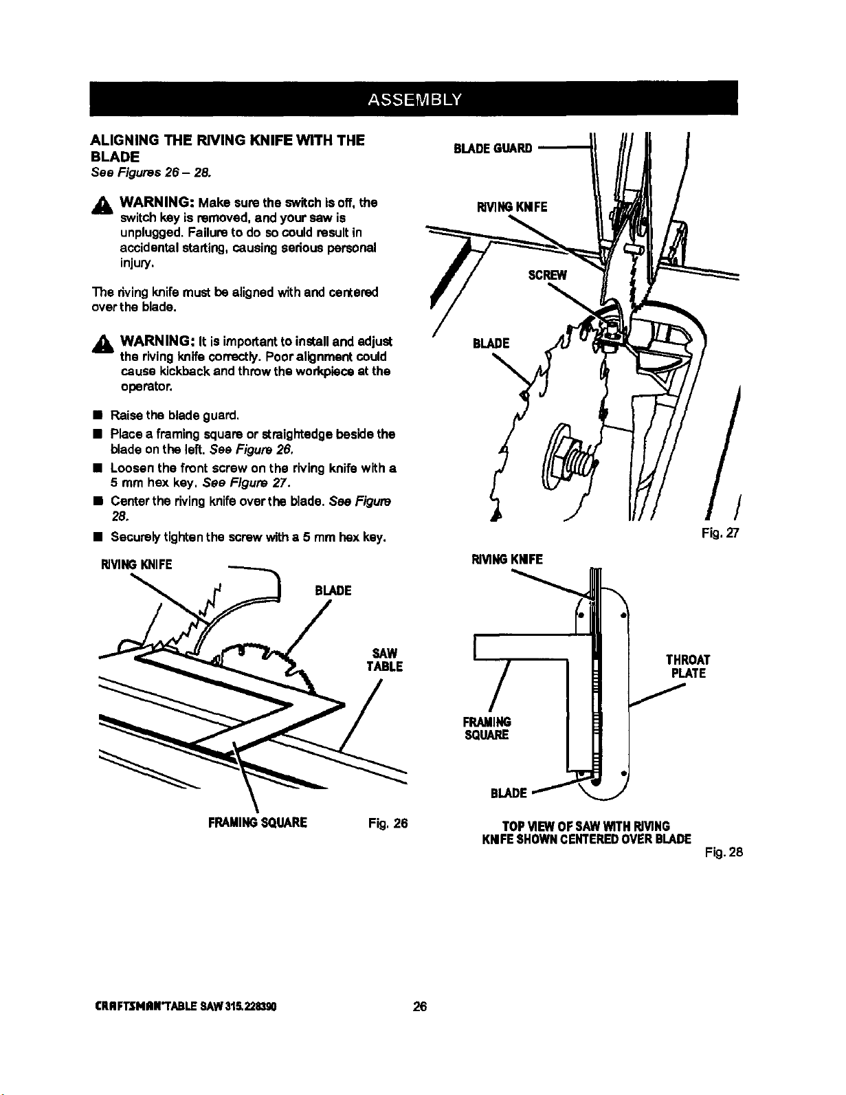
ALIGNING THE RIVING KNIFE WITH THE
BLADE
See Figures26 - 28.
_1_ WARNING: Make sure the switchisoff, the
switch key is removed, and your saw is
unplugged.Failureto do socouldresultin
accidentalstarting,causingsedous personal
injury,
The rivingknife mustbe alignedwith and centered
over the blade.
,_ WARNING: It isimportantto installand adjust
the rivingknifecorrectly.Pooralignmentcould
cause kickbackand throwthe workpieceat the
operator.
• Raise the bladeguard,
• Place a framing squareor straightedgebeside the
bladeon the left. See Figure 26.
• Loosen the front screw on the rivingknife with a
5 mm hex key. See Figure 27.
• Centarthe rivingknifeover the blade. See Figure
28.
• Securelytightenthe screwwitha 5 mm bex key.
RIVINGKNIFE
BLADE
SAW
TABLE
FRAMINGSQUARE Fig, 26
BLADEGUARD
RIVINGKNIFE
BLADE
RIVINGKNIFE
I
/
FRAMING
SQUARE
BLADEf
THROAT
PLATE
J
TOP MEW OF SAWWITHRIVING
KNIFESHOWNCENTEREDOVER BLADE
/
Fig,27
Fig.28
ICRRFTSNRR'TABLESAW315.228390 26
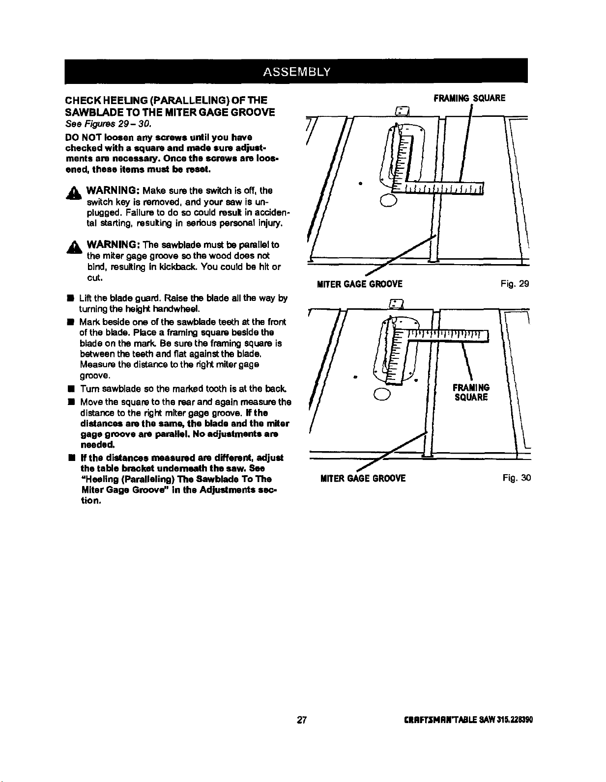
CHECK HEELING (PARALLELING) OF THE
SAWBLADE TO THE MITER GAGE GROOVE
See Figures29- 30.
DO NOT loosen any screws until you have
checked with a square and rode sure adjust-
ments are neceeaa_y. Once the screws are loos-
ened, these items must be reset.
Jl_ WARNING: Make surethe switchis off, the
switch key is removed, and your saw is un-
plugged. Failureto do so couldresult in acciden-
tal starting,resulting in serious personalinjury.
A WARNING: The sawblade mustbe parallelto
the miter gage groove sothe wooddoes not
bind,resultingin kickback.You could be hit or
cut.
• Liftthe blade guard. Raise the bladeall the way by
turningthe heighthandwbeel.
• Mark beside one ofthe sawbladeteeth at the front
of the blade. Place a framing squarebesidethe
bladeon the mark. Be surethe framingsquare is
between theteeth and fiat againstthe blade,
Measure thedistancetothe dghtmitergage
groove,
• Turn sawbladeso the marked toothis at the back.
• Move the square to the rear and again measure the
distance to the right miter gage groove. If the
distances are the same, the blade and the miter
gage groove are parallel. No adjustments are
needed.
• If the distances measured are different, adjust
the table bracket underneath the saw. See
"Heeling (Paralleling) The Sawblade To The
Miter Gage Groove" in the Adjustments se_.-
tion,
FRAMINGSQUARE
MITERGAGEGROOVE Fig. 29
MITER GAGE GROOVE Fig. 30
27 CRRFT.IflP4AN"T/_LE SAWalS,2281_
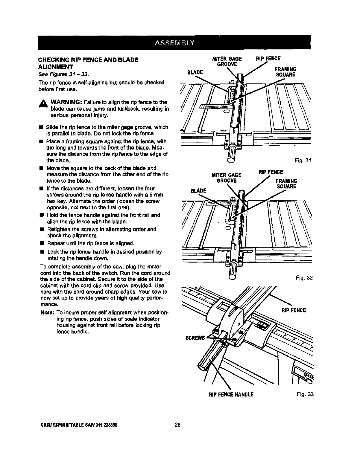
CHECKING RIP FENCE AND BLADE
ALIGNMENT
See Figures31 - 33.
The ripfence is self-aligningbut shouldbe checked
before first use.
• L WARNING: Failureto alignthe dp fenceto the
blade can cause jams and kickback,resulting in
sedous personal injury.
• Slide the dp fence tothe miter gage groove,which
is parallelto blade. Do not lock the dp fenne.
• Place a framing square againstthe dpfence, with
the longand towardsthefront of the blade. Mea-
surethe distancefrom the dpfence to the edge of
the blade,
• Movethe squareto the backof the bladeand
measurethe distancefrom the otherend ofthe tip
fenceto the blade,
• Ifthe distancesare different,loosenthe four
screwsaroundthe dpfence handlewith a 6 mm
hex key, Alternatethe order (loosenthe screw
opposite,not nextto the first one),
• Holdthe fence handleagainstthe fmot railand
alignthe ripfence withthe blade,
• Retightenthe screws inalternating order and
checkthe alignment,
• Repeat untilthe dp fence isaligned,
• Lock the ripfence handle in desired positionby
rotating the handle down.
To completeassembly of the saw, plugthe motor
cord intothe beck ofthe switch.Run the cordaround
the side ofthe cabinet. Secure itto the side ofthe
cabinetwith the cordclip and screw provided,Use
care withthe cord around sharp edges, Your sew is
now set upto provideyears of high quality perfor-
mance.
Note: To insure properserfalignmentwhen position-
ingdp fence, push skies of scale indicator
housingagainstfront railbefore lockingdp
fence handle.
BLADE
BLADE
MITERGAGE RIPFENCE
GROO_ _ FRAMINGSQUARE
MITERGAGE
GROOVE
Fig. 31
RIPFENCE
FRAMING
SQUARE
Fig. 32
RIPFENCE
RIPFENCEHANDLE
Fig. 33
CRIIFTSNRN'TABLESAW315,228390 28
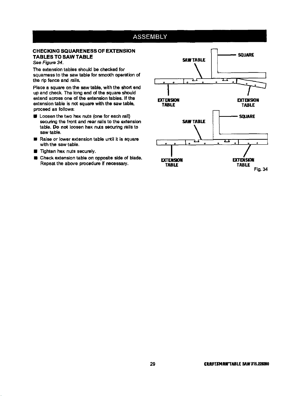
CHECKING SQUARENESS OF EXTENSION
TABLES TO SAW TABLE
See Figure34.
The extensiontables shouldbe checked for
squamess to the saw table for smoothoperationof
the ripfence and rails.
Place a square on the saw table, withthe shortend
up and check.The longend of the squareshould
extend across one of the extension tables. If the
extension table is not square with the saw table.
proceed as follows:
• Loosenthe two hex nuts (one for each rail)
securingthe front and rear railsto the extension
table. Do not loosen hex nuts secudng railsto
saw table,
• Raise or lowerextension table until itis square
with the saw table.
• "13ghtenhex nuts securely.
• Check extension table on oppositeside of blade.
Repeat the above procedureif necessary.
SAWTABLE
o o
I
EXTENSION
TABLE
EXTENSION
TABLE
F-1
SAWTABLE [ _'_- SQUARE
II ,-,., I
EXTENSION I_DI,_ON
TABLE TABLE
Fig.34
29 CRBFT._'MBrI'ABLE,_W $18.2211_0
To avoid unnecessary setups and adjustments,a
good practiceis to checkyour setupscarefullywith a
framing squareand make practicecuts in scrapwood
before makingfinish cuts in good workpieces,Do not
start any adjustments untilyou have checked with a
square and made test cutsto be sureadjustments
are needed,
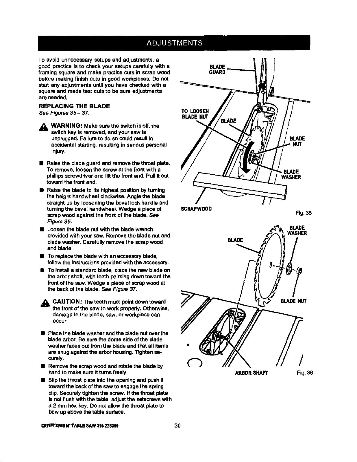
REPLACING THE BLADE
See Figures35- 37.
_lb WARNING: Make sure the switchisoff, the
switchkey isremoved, and your saw is
unplugged,Failureto do socouldresult in
accidental starting,resultingin seriouspersonal
injury,
TO LOOSEN
BLADENUT
GUARD
BLADE
NUT
• Raise the blade guard and removethe throatplate.
To remove, loosen the screwat the frontwith a
phillipsscrewdriverand liftthefront end. Punitout
towardthe frontend.
• Raise the blade to itshighest positionbyturning
the heighthandwheelclockwise.Angle the blade
straight up by looseningthe bevel lockhandle and
turningthe bevel handwheel. Wedge a piece of
scrapwood againstthe frontofthe blade. See
Figure35.
• Loosenthe blade nutwith the bladewrench
providedwith your saw,Remove the blade nutand
bladewasher, Carefullyremove the scrap wood
and blade.
• To replacethe bladewith an accessoryblade,
followthe instructionsprovidedwith the acceseorj.
• To installa standard blade, place the new bladeon
thearbor shaft,with teeth pointingdowntowardthe
frontofthe saw,Wedge a piece ofscrap woodat
the backof the blade. See Figure37.
• k CAUTION: The teeth mustpointdowntoward
the frontofthe saw to work properly.Otherwise,
damage to the blade, sew, or workpiececan
occur.
SGRAPWOOD
BLADE
/
/
!
.BIADE
WASHER
Fig. 35
l BLADENUT
• Placethe bladewasher and the bladenutover the
blade arbor.Be surethe dome side ofthe blade
washerfaces outfrom the blade and that all items
are snugagainstthe arbor housing.Tightense-
curely.
• Remove the scrapwoodand rotatethe blade by
handto make sureitturnsfreely,
• Slipthe throatplate intothe opening and pushit
towardthe backofthe saw to engagethe spring
clip,Securelytightenthe screw. If the throatplate
isnotflushwiththe table, adjustthe setscrewswith
a 2 mm hex key.Do not allowthe throatplate to
bow upabove thetable surface.
ARBORSHAFT
/
Fig.36
[RRFTSMRN"TABLESAW315.228390 30
SCRAPWOOD
BLADEGUARD
3LADE
NUT
BLADE
WASHER
TOTIGHTEN
BLADEHUT Fig.37
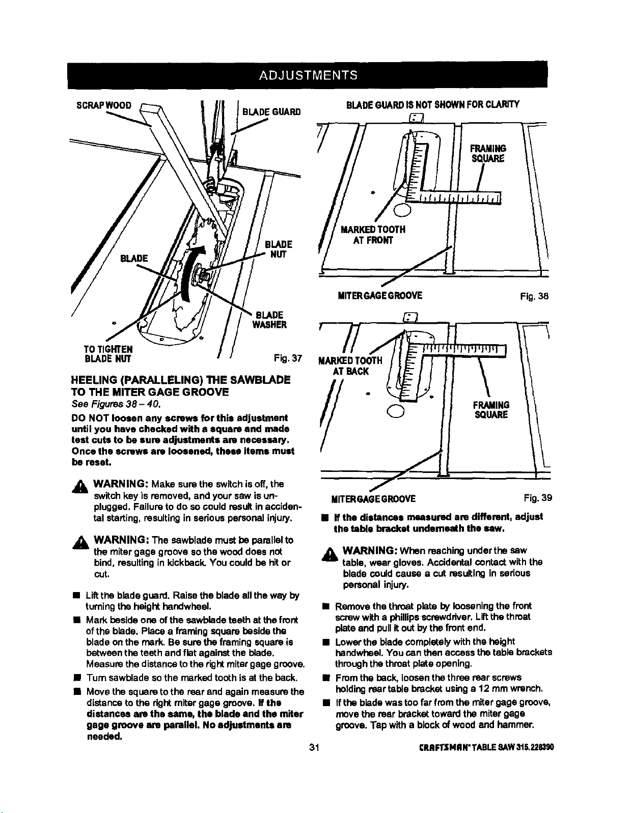
HEELING (PARALLELING) THE SAWlBLADE
TO THE MITER GAGE GROOVE
See Figures38- 40.
DO NOT loosen any screws for this adjustment
until you have checked with a square and made
test cuts to be sure adjustments am necessmy.
Once the screws are loosened, these Items must
be reset.
BLADEGUARDISNOTSHOWNFORCLARITY
f
MITERGAGEGROOVE Fig. 38
MARKEDTOOTH
ATBACK
//+
WARNING: Make sure the switchisoff, the
switchkey is removed, and your saw isun-
plugged,Failureto do so could resultin acciden-
tal starting,resultingin seriouspersonalinjury.
,_ WARNING: The sawblademust be parallelto
the mitergage groove sothe wooddoes not
bind,resulting in kickback,You couldbe hitor
cut.
• Liltthe bladeguard.Raise the bladeell theway by
turningthe heighthandwheel.
• Mark besideone ofthe cawblade teeth at thefront
ofthe blade. Place a framing squarebesidethe
blade onthe mark. Be surethe framing square is
between theteeth and flat againstthe blade.
Measure thedistancetothe rightmitergagegroove.
• Turn sawblade sothe marked toothis at the back.
• Move the squareto the rear and againmeasure the
distanceto the rightmitergage groove. If the
distances are the same, the blade and the miter
gage groove are parallel. No adjustments am
needed.
MITERGAGEGROOVE Fig.39
• If the distances measured are different, adjust
the table bracket underneath the saw.
j_ WARNING: When reachingunderthe sew
table, wear gloves. Accidentalcontactwith the
blade could cause a cut resulting in serious
personal injury.
• Removethe throatplate by looseningthe front
screwwitha phillipsscrewdriver,Liftthethroat
plateand pullitout by the frontend,
• Lowerthe bladecomplatalywith the height
handwheel.You canthen access thetable brackets
throughthe throatplateopening,
• Fromthe peck, loosenthe three rear screws
holdingrear table bracket usinga 12 mm wrench,
• Ifthe bladewas too farfrom the miter gage groove,
movethe rear brackettowardthe mitergage
groove,Tap with a blockofwood and hammer.
31 CRRFI"tMRN"TABLE:SAW315.228390
• Ifthe bladewas too close to the miter gage
groove, backthe bracket away with the blockof
woodand hammer.
• Tightenthe screws, raise the blade and recheck.
• Repeat untilblade is parallelto mitergage groove,
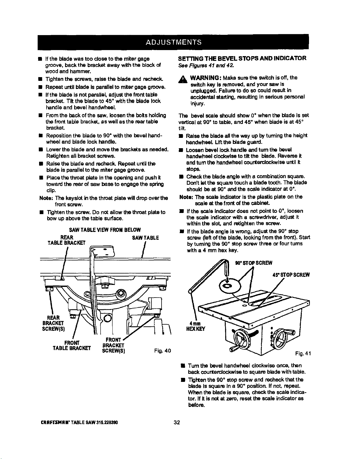
• Ifthe blade isnot parallel, adjustthefronttable
bracket.Tiltthe blade to 45° with the blade lock
handleand bevel handwheal.
• Fmmthe beckofthe saw, loosenthe boltsholding
thefront table bracket,as well as the reartable
bracket.
• Repositionthe bladeto 90° with the bevel hand-
wheel end bladelock handle.
• Lowerthe blade and movethe bracketsas needed,
Retiglten all bracketscrews.
• Raisethe blade and recheck.Repeat untilthe
bladeisparallelto the miter gage groove.
• Placethe throatplate in theopeningand pushit
towardthe rear of sew base toengage the spring
clip.
Note; The keyslotinthe throatplate willdrop overthe
frontscrew,
• Tightenthe screw,Do not allowthe throatplatato
bow up above thetable surface.
SAW TABLEVIEW FROMBELOW
REAR SAWTABLE
TABLEBRACKET /
BRACKET/ r'"l I
SCREW(sl/ l I 7--7 L\
I FRONT/
FRONT BRACKET
TABLEBRACKET SCREW(S) Fig. 40
SETTING THE BEVEL STOPS AND INDICATOR
See Figures41 and 42.
A WARNING: Make surethe switchisoff, the
switchkey is removed,andyour sew is
unplugged.Failuretodo socould resultin
accidentalstarting, rasuitingin sedous personal
ir_u_.
The bevel scaleshouldshow0° when the blade isset
verticalat 90° totable, and 45° when bladeisat 45°
tilt,
• Raise the bladeall theway up byturningthe height
handwhsel. Lift the bladeguard.
• Loosenbevel lock handleand tam the bevel
handwhselclockwiseto tiltthe blade, Ravemeit
and turnthe handwheelcounterclockwiseuntilit
stops,
• Checkthe bladeangle witha combinationsquare.
Don't letthe squaretoucha bladetooth,The blade
shouldbe at 90° and the scala indicatorat 0°.
Note: The scale indicatoristhe plastic plate on the
scaleat thefrontof the cabinet.
• Ifthe scale indicatordoes notpointto 0°, loosen
the scale indicatorwith a screwdriver,adjust it
withinthe slot,and retightenthe screw.
• Ifthe blade angleIswrong, adjustthe 90° stop
screw(leftofthe blade, lookingfrcm thefront),Start
byturningthe 90° stop screwthree or four rums
witha 4 mm hex key.
4mm
HEXKEY
90°STOPSCREW
45' STOPSCREW
Fig.41
• Turn the bevel handwheelclockwiseonce,then
beck counterclockwise to squarebladewithtable.
• Tightenthe 90° stop screwand recheck thatthe
blade issquarein a 90" position.If not,repeat,
When the bladeis square, checkthe scala indica-
tor. If it isnotat zero, resetthe scale indicatoras
before.
CRRFrSNRN"TABLESAW316._83g0 32

• Check the 45° setting.Tilt the bladewith the bevel
handwheelas far as it willgo to the left. Placethe
squareagainstthe blade(be surethe squareisnot
againstone of the saw teeth). If the blade isnot at
45°, unscrewthe 45 ° stop screw (dghtof blade),
turnthe hendwheel untilthe blade iscorrect,and
tightenthe screw. Recheck and repeat ifneces-
seW.
• Check that the scale indicatorisat 45°,
• If not,loosenthe scaleindicatorwith a screwdriver,
adjustitwithinthe slot,and retightenthe screw.
• Loosenknoband pull outon stop pinto rotate
miter gage base pest stop screws.
• Loosenthe lock nut ofthe 0° stop screwat the
stop pinwith a 8 mm wrench.
• Place a 90" square againstthe miter gage rodand
the mitergage base.
• If the rodisnot square, loosenthe knob, adjustthe
rod, and tightenthe knob.
• Adjustthe 0° stop screwuntil it rests againstthe
stop pin.
• Adjustthe plusand minus45° stop screws usinga
45° tdangle and the stepsabove,
MITER
GAGEROD MITER
GAGEBASE
KNOB
SCALE
INDICATOR
Fig, 42
ADJUSTING THE MITER GAGE
See Figure 43.
You can setthe miter gage at 0° and plusor minus
45° withthe mitergage stop pinand adjustable stop
SCreWS,
Note: The mitergage providescloseaccuracy in
angled cuts. For very closetolerances,test
cutsare recommended.
45'
STOPSCREW
0° ADJUSTABLE
STOPSCREW
LOCKNUT
STOPPIN
Fig. 43
33 CRflFTSMRN"TABLESAW316.228390
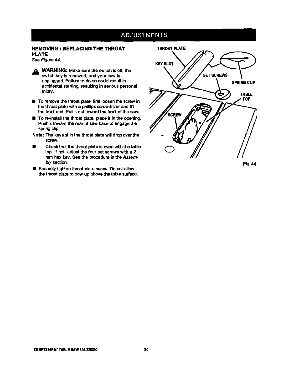
REMOVING I REPLACING THE THROAT
PLATE
See Figure44.
_k WARNING: Make surethe switchisoff, the
switchkey is removed,and yoursaw is
unplugged.Failureto do socould resultin
accidental starting,resultingin sadous personal
injury.
• To remove the throatplata,first loosenthescrewin
the throatplatewith a phillipsscrewdriver and lift
the frontend. Pullit outtowardthe frontof the saw.
• To re-installthe throat plate, place it in the opening.
Push ittowardthe rear ofsaw baseto engagethe
springclip.
Note: The keyslot inthe throatplata willdrop overthe
screW.
• Check thatthe throatplate iseven withthe table
top. If not, adjustthe four sat screws witha 2
mm hex key.See the procedureinthe Assam-
b/y section.
• Securelytightenthmat plata screw. Do notallow
thethroatplateto bow up above thetable surface.
THROATPLATE
KEYSLOT
SPRINGCUP
TABLE
Fig.44
CRRFI"SHHN"TABLESAW31S.2283gO 34
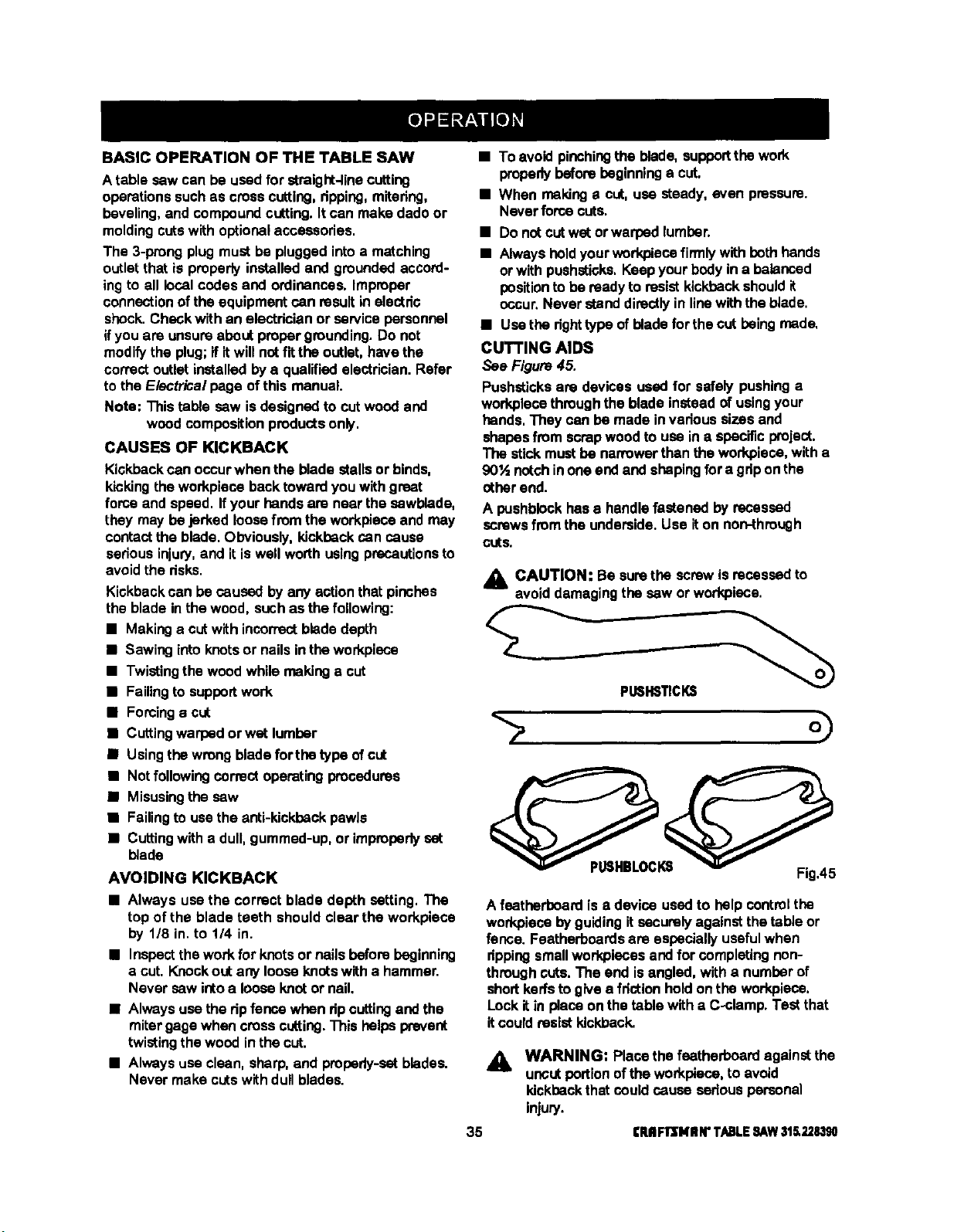
BASIC OPERATION OF THE TABLE SAW
A table sew can be used for straight-linecutting
operationssuchas crosscutting,dpping,mitadng,
beveling,and compoundcutting.It can make dadoor
moldingcutswith optionalaccessories.
The 3-prong plugmust be pluggedintoa matching
outletthat is properlyinstalledand groundedaccord-
ing to all localcodes and ordinances. Improper
connectionof the equipmentcan resultin electdc
shock.Check with an electdcian or servicepersonnel
ifyou are unsureabout propergrounding.Do not
modifythe plug;if itwillnotfit the outlet,have the
correctoutletinstalledbya qualified electrician.Refer
to the Electrical page of this manual.
Note; Thistable sew isdesignedto cutwood and
woodcompositionproductsonly,
CAUSES OF KICKBACK
Kickbackcan occurwhen the blade stallsor binds,
kickingthe workplace backtowardyou with great
force and speed. If your handsare near the sewblade,
they may be jerked loosefrom the workplaceand may
contactthe blade. Obviously,kickbackcan cause
sedous injury,and itis well worthusingprecautionsto
avoidthe risks.
Kickbackcan be caused by any actionthat pinches
the blade in the wood, such as the following:
• Making a cutwith incorrectbladedepth
• Sawingintoknotsor nailsin theworkplace
• Twistingthewood whilemakinga cut
• Failingto supportwork
• Forcinga cut
• Cuttingwarped or wet lumber
• Usingthewrong bladefor tho typeofcut
• Not following correctoperatingprocedures
• Misusingthe saw
• Failingto usethe anti-kickback pawls
• Cuttingwith a dull,gummed-up,or impmpodyset
blade
AVOIDING KICKBACK
• Always use the correct blade depth setting, The
top of the blade teeth shouldclear the workpiece
by 1/8 in.to 114 in.
• Inspectthe work for knotsor nailsbeforebeginning
a cut, Knockout any looseknotswith a hammer.
Never sew ictoa loose knotor nail.
• Alwaysuse the dp fencewhen dp cutting and the
mitergage when crosscutting.This helpsprevent
twistingthewood inthe cut.
• Alwaysuse clean, sharp, and propsdy-satblades.
Never make cutswithdull blades.
• To avoid pinchingthe blade, supportthe work
properlybeforebeginninga cut.
• When makinga cut, use steady, even pressure.
Never forcecuts.
• Do notcutwet orwarpsd lumbar.
• Always hold yourworkpiesefin'nlywith beth hands
or withpushstioks,Keep yourbodyin a balanced
position to be readyto resist kickbackshouldit
occur.Never standdirectlyin linewiththe blade.
• Usethe dghttype of blade for the cutbeing made,
CUTTING AIDS
See Figure45.
Pushsticksare devices used for safely pushinga
workplacethroughthe blade insteadofusingyour
hands,They can be made in vadoussizes and
shapesfrom scrapwoodto use ina specificproject.
The stickmustbe nanmwarthanthe workpieca,with a
90'A notchinoneendand shapingfora gdponthe
other end.
A pushblockhas e handlefastened by recessed
screwsfromthe underside.Use iton non-through
CutS,
A CAUTION: Be surethe screwisrecessedto
avoiddamagingthe sew orworkplace.
PLI6HSTICKS
A feather'boardis adevice used to help controlthe
workplacebyguidingit securelyagainstthetable or
fence. Featherboardsare especiallyusefulwhen
dpping smallwodqolecesand for completingnon-
throughcuts. The end isangled, with a numberof
shortkerfsto give a frictionhold onthe workpiese,
Lock it in place on thetable witha C-clamp. Testthat
itcould resistkickback.
&
35
WARNING: Placethe featherboardagainstthe
uncutportionofthe workplace,to avoid
kickback thatcould cause sedous personal
injury.
rRIIFIrSHIIN"T/L,BLESAW31_228,190
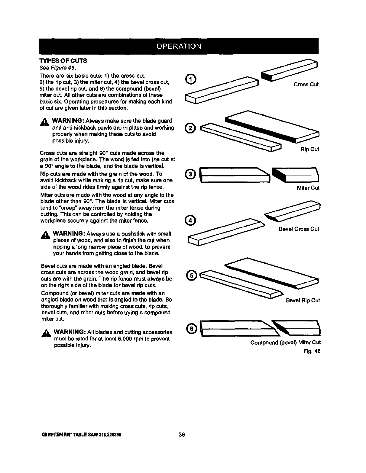
TYPESOFCUTS
See Figure46.
There are six basic cuts: 1) the cress cut,
2) the ripcut, 3) the mitercut, 4) the bevel cresscut,
5) the bevel dp cut,and 6) the compound(bevel)
miter cut, AJIothercutsare combinationsofthese
basic six. Operatingproceduresfor makingeach kind
of cutare givenlater inthis section,
_, WARNING: Always make surethe bladeguard _ ,t._.._=_ _.._
and anti-kickbackpawls are in place and working IzJ
properlywhen makingthese cutsto avoid
v
possibleinjury.
Cross cutsare straight90° cutsmade across the RipCut
grain of the workpiece, The wood isfed intothe cut at
a 90° angle to the blade, and the blade isvertical.
Ripcutsare made with the grain ofthe wood. To
avoid kickback while making a dp cut, make sure one
sideof the wood ridesfirmlyagainstthe dp fence.
Mitercutsare made withthe wood at anyangleto the
blade otherthan 90°. The blade is vertical. Miter cuts
tendto _creep" away from the miterfence during
cutting.This can be controlledby holdingthe
work.piecesecurelyagainstthe miterfence,
_. WARNING: Always usea pushstickwith small
piecesofwood, and also to finishthe cutwhen
rippinga long narrow piece ofwood, to prevent
your handsfrom getting closetothe blade.
®
MiterCut
o
Bevel CrossCut
Bevel cutsare made withan angled blade. Bevel
crosscutsare acrossthe woodgrain,and bevel rip
cutsare withthe grain. The ripfence must always be
on the rightsideof the blade for bevel dp cuts.
Compound(or bevel) miter cutsare made with an
angled blade on woodthat isangled to the blade. Be
thoroughlyfamiliar with makingcresscuts, ripcuts,
bevel cuts,and miter cutsbefore tryinga compound
mitercut,
_IL WARNING: All blades and cuttingaccessories
mustbe rated for at least 5,000 rpmto prevent
possibleinjury.
Bevel RipCUt
Compound(bevel) MiterCUt
Fig, 46
CRRFTSNRII"TABLESAW315.228390 36
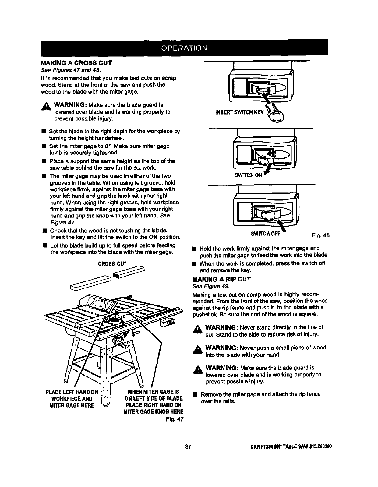
MAKING A CROSS CUT
See Figures47 and 48.
It is recommendedthat you make test cuts on scrap
wood. Stand at the front of the saw and pushthe
wood to the bladewith the miter gage.
_lb WARNING: Make sure the blade guard is
loweredover blade and isworkingproperlyto
preventpossibleinjury.
• Set the bladetothe dghtdepthfor thewod<pleceby
tumingthe height handwheel.
• Set the mitergage to 0°. Make sum mitergage
knob is securelytightened.
• Place a supportthe same heightas the topof the
sawtable behindthe saw for thecutwork.
• The mitergage may be used in either ofthetwo
groovesinthetable. When usingleftgroove,hold
workpiecefirmlyagainstthe mitergage basewith
your left:handand gdpthe knobwithyourright
hand,When usingthe rightgroove, holdworkpiece
firmlyagainstthe miter gage basewithyour right
handand gripthe knobwithyour lefthand. See
F/gum 47.
• Check thatthe wood isnottouchingthe blade.
Insertthe key and liftthe switchto the ON position.
• Letthe blade buildupto full speed beforefeeding
theworkpieceintothe bladewiththe miter gage.
CROSScur
PLACELEFTHAND ON
WORKPIECEAND
MITER GAGEHERE
WHENMITERGAGEIS
ON LEFT SiDEOF BLADE
PLACERIGHTHAND ON
MITERGAGEIOiOR HERE
Fig. 47
SWITCHOFF
Fig. 48
• Hold thework firmlyagainstthe miter gage and
pushthe mitergageto feed the workintothe blade.
• When the work iscompleted,press the switch off
and removethe key,
MAKING A RIP CUT
See Figure49.
Maldnga test cuton scrapwood is highlyrecom-
mended. Fromthefrontofthe saw, positionthe wood
against the dp fence and pushit to the bladewitha
pushstick, Be sumthe end ofthe wood is square.
_lb WARNING: Never standdirectly inthe lineof
cut, Stand to the side to reducedskof injury.
_1_ WARNING: Never pusha small piece ofwood
Into the bladewithyour hand.
,d_ WARNING: Make surethe blade guard is
loweredover bladeand isworkingproperlyto
preventpossible injury,
• Removethe mitergage andattachthe dpfence
overthe roils.
37 CRRFlr'SNIIN"TABLESAW31S.228390
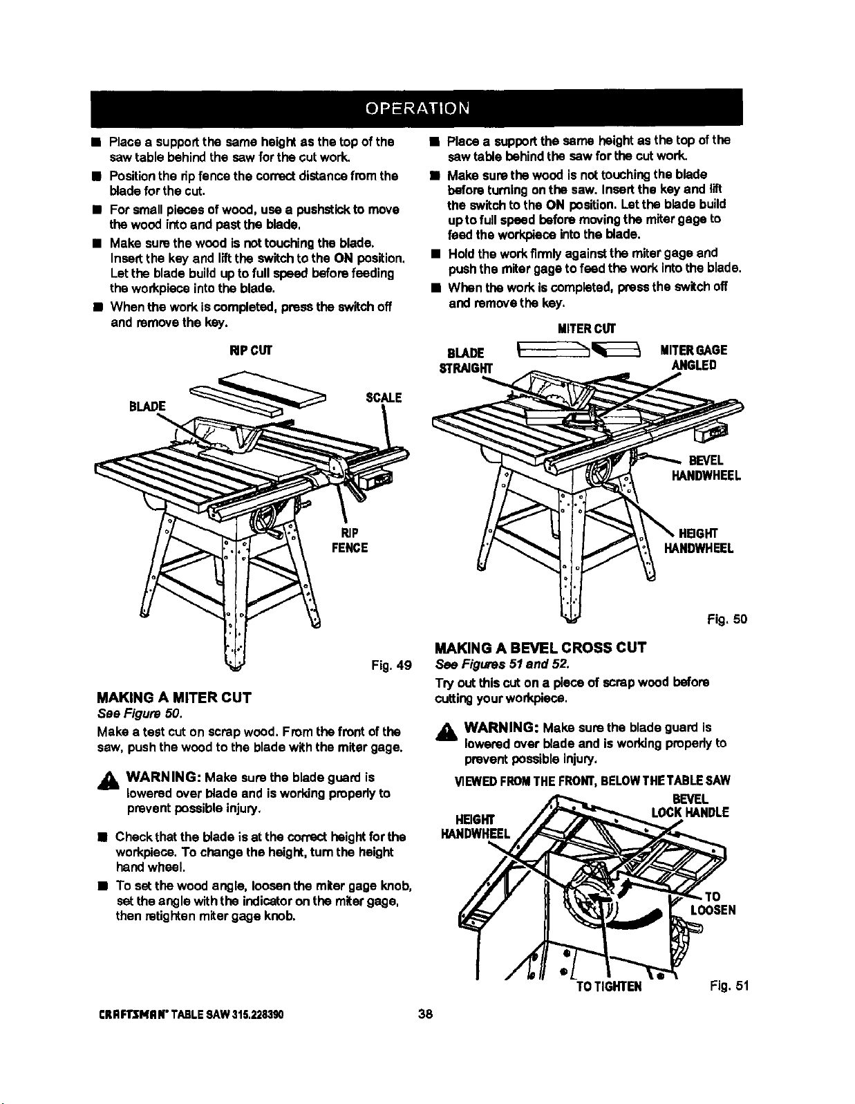
• Placea supportthe same heightas the topofthe
sawtable behindthe saw for the cut work.
• Positionthe dpfencethe correct distancefrom the
bladeforthe cut.
• For smallpieces ofwood, use a pushstickto move
thewood intoand pastthe blade,
• Make surethe wood isnottouchingthe blade.
Insertthe key and liftthe switchto the ON position.
Letthe bladebuildupto full speed beforefeeding
the workpiecointothe blade.
• When the work iscompleted,pressthe switch off
and removethe key.
RiPCUT
BLADE
SCALE
BF
FENCE
Fig. 49
MAKING A MITER CUT
See Figure 50.
Make a test cut on scrap wood, Fromthe frontofthe
saw, pushthe woodto the bladewith the miter gage.
j_, WARNING: Make sure the bladeguard is
lowered over blade and isworkingpropedyto
preventpossibleinjury.
• Check thatthe blade isat the correct height for the
workpiece,To change the height,turnthe height
handwheel.
• To setthe wood angle, loosenthe miter gage knob,
setthe angle withthe indicatoron the mitergage,
then retightenmitergage knob.
• Place a supportthe same height as thetop ofthe
sawtable behindthe saw for the cutwork.
• Make sure thewood isnottouchingthe blade
beforeturningonthe saw. Insertthe key and lift
the switch to the ON position. Letthe bladebuild
uptofullspeed beforemovingthe mitergage to
feed theworkplacointothe blade.
• Holdthe workfirmlyagainstthe mitergage and
pushthe mitergage to feed the work intothe blade.
• When thework iscompleted,pressthe switch off
and remove the key,
MITERCUT
BLADE ____________ MITERGAGE
STRAIGHT ANGLED
BEVEL
HANDWHEEL
HANDWHEEL
Fig, 50
MAKING A BEVEL CROSS CUT
See Figures 51 and 52.
Try out thiscut ona pieceof scrapwoodbefore
cuttingyourworkpiece,
,_ WARNING: Make surethe blade guard is
lowered over blade and is workingpmpedyto
preventpossible injury,
!/1EWEDFROMTHE FRONT,BELOWTHE TABLESAW
BEVEL
HEIGHT LOCKHANDLE
HANDWHEEL
LOOSEN
TOTIGHTEN Fig. 51
CRRFll3MR N"TABLE SAW 315.228390 38
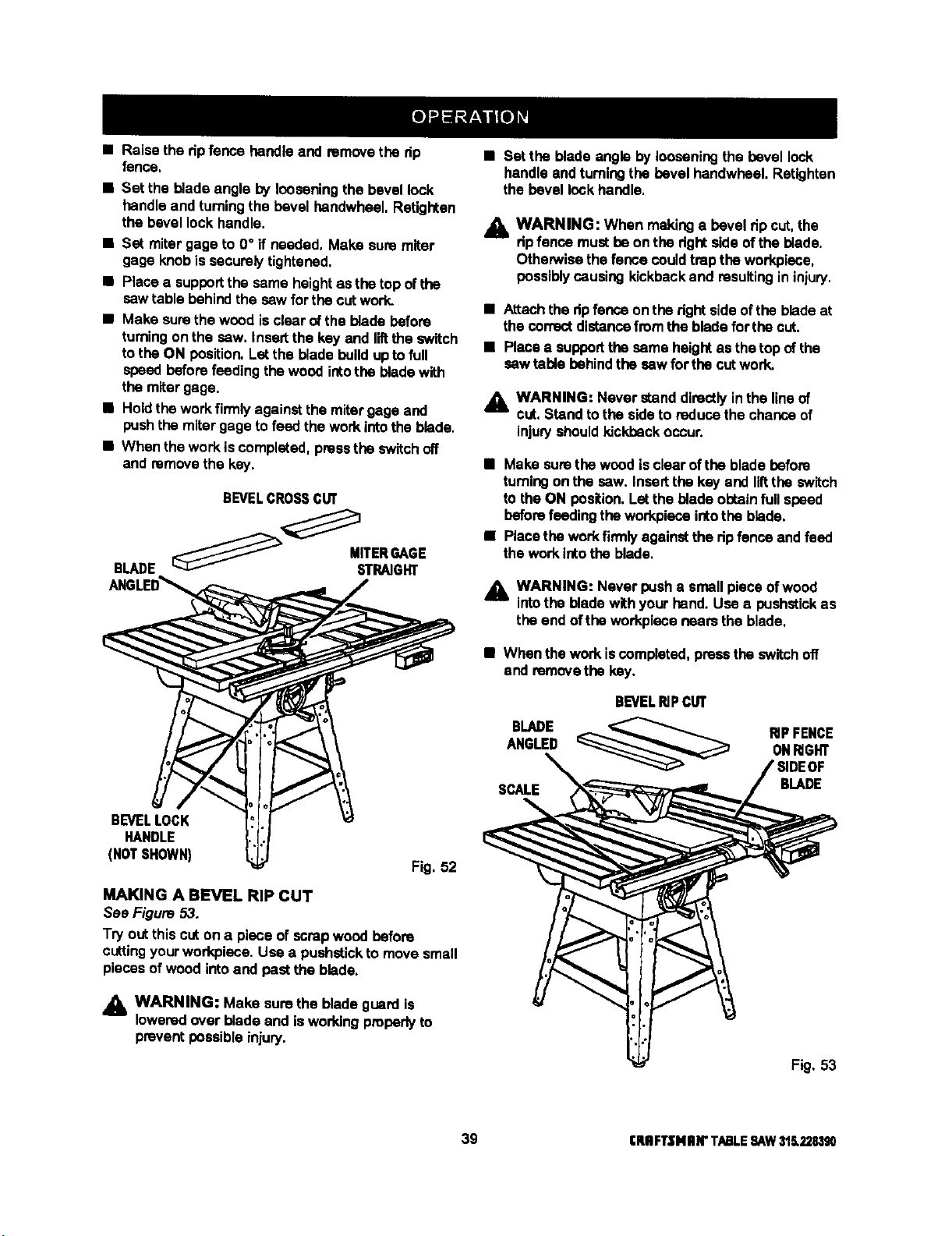
• Raise the dp fence handleand remove the dp
fence,
• Set the blade angle by looseningthe bevel lock
handle and turningthe bevel handwheel. Retighten
the bevel lock handle.
• Set miter gage to 0° if needed. Make sure miter
gage knobis securelytightened.
• Place a supportthe same heightas the top ofthe
sawtable behindthe sew forthe cutwork.
• Make surethe wood isclear of the blade before
turningon the saw, Insertthe key and liftthe switch
tothe ON position.Letthe blade buildupto full
speedbeforefeeding thewood intothe blade with
the mitergage.
• Holdthe workfirmlyagainstthe mitergage and
pushthe mitergage to feed thework intothe blade.
• When thework is completed,pressthe switch off
and remove the key.
BEVELCROSSCUT
BEVELLOCK
HANDLE
(NOTSHOWN)
Fig. 52
MAKING A BEVEL RIP CUT
See Figure 53.
Try outthis cuton a piece of scrapwood before
cuttingyourworkplace.Use a pushstickto move small
piecesof woodintoand pastthe blade.
_k WARNING: Make sure the blade guard is
loweredover blade and isworkingproperlyto
prevent possible injury.
• Set the bladeangle by looseningthe bevel lock
handle andturningthe bevel handwhael. Retightan
the bevel lockhandle.
.1_ WARNING: When makinga bevel tip cut,the
dp fence mustbe on the dghtside ofthe blade.
OthenNisethefence couldtrap the workpiece,
possibly causing kickbackand resultingin injury.
• Attachthe dp fenceon the rightsideofthe bladeat
the correctdistancefromthe blade forthe cut.
• Placea supportthe same heightas thetop of the
sew table behindthe sew for the cutwork.
,_, WARNING: Never standdirectlyinthe lineof
cut, Stand tothe side to reduce the chance of
injuryshouldkickback occur.
• Make surethe wood isclearofthe bladebefore
turningontha sew. Inserttha key and liftthe switch
to the ON position. Letthe blade obtainfullspeed
beforefeedingthe workplaceintothe blade.
• Placethe workfirmlyagainstthe ripfence andfeed
the work intothe blade.
_l, WARNING: Never pusha small piece ofwood
intothe blade withyour hand. Use e bushstick as
the end oftha workpiece nears the blade.
• When the work iscompleted,pressthe switch off
and removethe key.
BLADE
ANGLED
SCALE
BEVEL_PC_
B_DE
Fig. 53
39 CRRFTSNIIN"TABLE9AW316.228,190
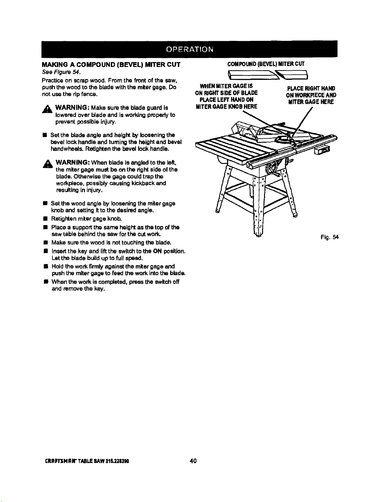
MAKING A COMPOUND (BEVEL) MITER CUT
See Figure 54.
Practice on scrap wood. Fromthe frontof the saw,
pushthe woodto the blade withthe mitergage. Do
notuse the ripfence,
• 1=WARNING: Make surethe bladeguard is
loweredover blade and is workingpropedyto
prevent possibleinjury.
• Set the bladeangle and heightby looseningthe
bevel lockhandle and turningthe heightand bevel
handwheels.Retightenthe bevel lock handle.
_lh WARNING: When blade isangled tothe left,
the miter gage must be onthe dgntsideof the
blade. Othew/ise the gage couldtrap the
workplece, possibly causingkickbackand
resulting in injuly.
• Set the woodanglo by looseningthe mitergage
knoband settingittothe desiredangle.
• Retightenmitergage knob.
• Placea supportthe same heightas the top ofthe
sew table behindthe sew for the cutwork.
• Make sumthe wood isnottouchingthe blade.
• Insertthe key and llftthe switchtothe ON position,
Letthe bladebuildup tofull speed.
• Holdthe workfirmlyagainstthe mitergage and
pushthemiter gage to feed thework into the blade.
• When thework iscompleted,pressthe switchoff
and removethe key.
COMPOUND(BEVEL)MITERCUT
WHENMITERGAGEIS
ON RIGHTSIDEOF BLADE
PLACELEFT HANDON
MITERGAGEKNOB HERE
PLACERIGHTHAND
OHWORKPIECEAND
MITERGAGEHERE
Fig. 54
CRflFrsM RN"TABLESAW318.228390 40
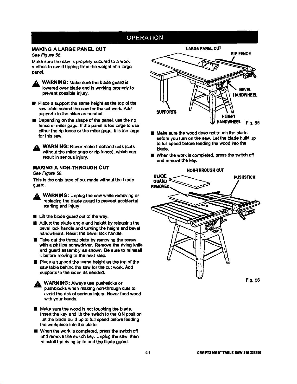
MAKING A LARGE PANEL CUT
Sea Figure 55.
Make surethe saw is properlysecuredto a work
surfaceto avoidtippingfromthe weight ofa large
panel.
LARGEPANELCUT
RIPFENCE
,_ WARNING: Make sure the blade guard is
lowered over bladeand isworkingproperlyto
preventpossibleinjury.
• Place a supportthe same heightasthe top ofthe
sawtable behindthe saw forthe cut work.Add
supportsto the sidesas needed.
• Dependingonthe shape of the panel, usathe dp
fence or miter gage. Ifthe panelistoo large to usa
eitherthe ripfence or the mitergage. itistoo large
for this saw.
_lh WARNING: Never make freehand cuts(cuts
withoutthe mitergage or ripfence), whichcan
result in sarious injury.
MAKING A NON-THROUGH CUT
See Figure 56.
This isthe onlytype ofcut made withoutthe blade
guard.
WARNING: Unplug the saw while removing or
replacing the blade guard to prevent accidental
starting and injury,
BEVEL
HANDWHEEL
SUPPORTS
HBGHT
HANDWHEEL Fig. 55
• Make surethe weed doesnottouchthe blade
beforeyouturnon the saw. Letthe bladebuildup
tofullspeed beforefeedingthe woodintothe
blade.
• When thework isccmp|efed, pressthe switchoff
and removethe key.
NON-THROUGHCUT
BLADE
GUARD
PUSHSTICK
• LiRthe bladeguard out ofthe way.
• Adjustthe bladeangle and height byreleasingthe
bevel lockhandleand turningthe heightand bevel
handwheels.Reset the bevellock handle.
• Take out the throat plate by removingthe screw
with a phillipsscrewdriver. Remove the rivingknife
and guardassembly as shown. Be sureto reinstall
it beforemovingto the nextstep.
• Placea supportthe same height as the top ofthe
saw table behind the saw for thecutwork.Add
supportsto the sides as needed.
_IL WARNING: Always usa pushsticksor
pushblaokswhen makingnon-throughcutsto
avoidthe risk ofserious injury.Never feed wood
withyour hands.
Fig. 56
• Make surethe wood is not touchingthe blade.
Insertthe key and liftthe switch tothe ON position.
Letthe bladebuildupto fullspeed beforefeeding
the workpieceintothe blade.
• When the workis completed,pressthe switchoff
and removethe switchkey.Unplugthe saw, then
reinstallthe rivingknife and the bladeguard.
41 I;RRF13NII N"TABLESAW315.228390
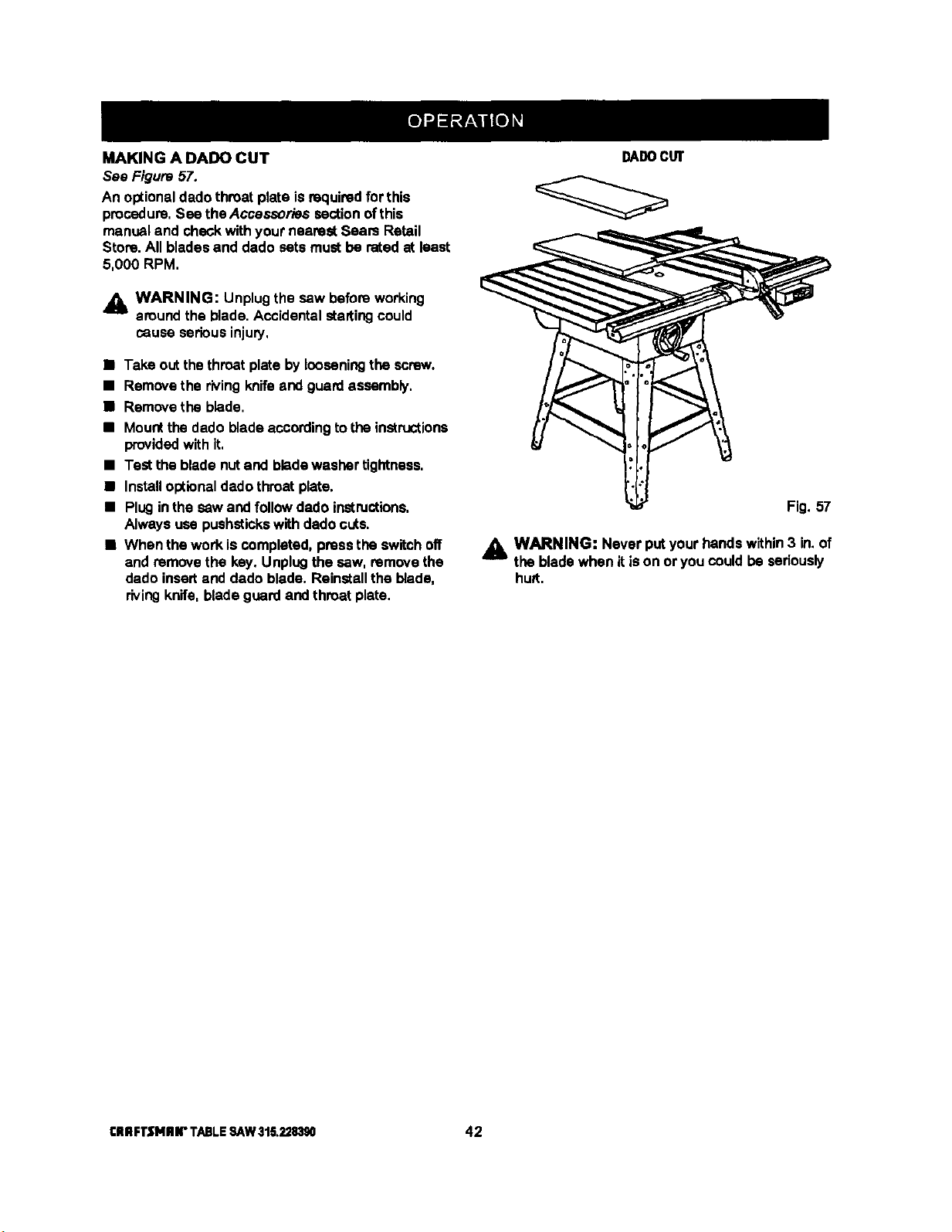
MAKING A DADO CUT
See Figure 5Z.
An optionaldado throat plate is requiredfor this
procedure,See the Accessories sectionofthis
manual and checkwithyour nearest Seam Retail
Store.All bladesand dado sets mustbe rated at least
5,000 RPM,
,_ WARNING: Unplugthe saw beforeworking
aroundthe blade. Accidentalstartingcould
cause seriousinjury,
• Take outthe throatplate by loosening the screw.
• Remove the rivingknifeend guardassembly,
• Remove the blade.
• Mountthe dado bladeaccordingto the instructions
providedwith it,
• Test the bladenut and bladawesher tightness.
• Installoptionaldado throatplate.
• Pluginthe sew and followdado instructions.
Always use pushstickswith dadocuts.
• When the work is completed,pressthe switchoff
and remove the key. Unplugthe saw. remove the
dado insertand dado blade. Reinstallthe blade,
rivingknife, bladeguard and throat plate.
DADOCUT
Fig. 57
_1= WARNING: Never put your handswithin3 in.of
the bladewhen it ison or you could be seriously
hu_t.
CIIRFI"SNIIIr TABLESAW315,228390 42
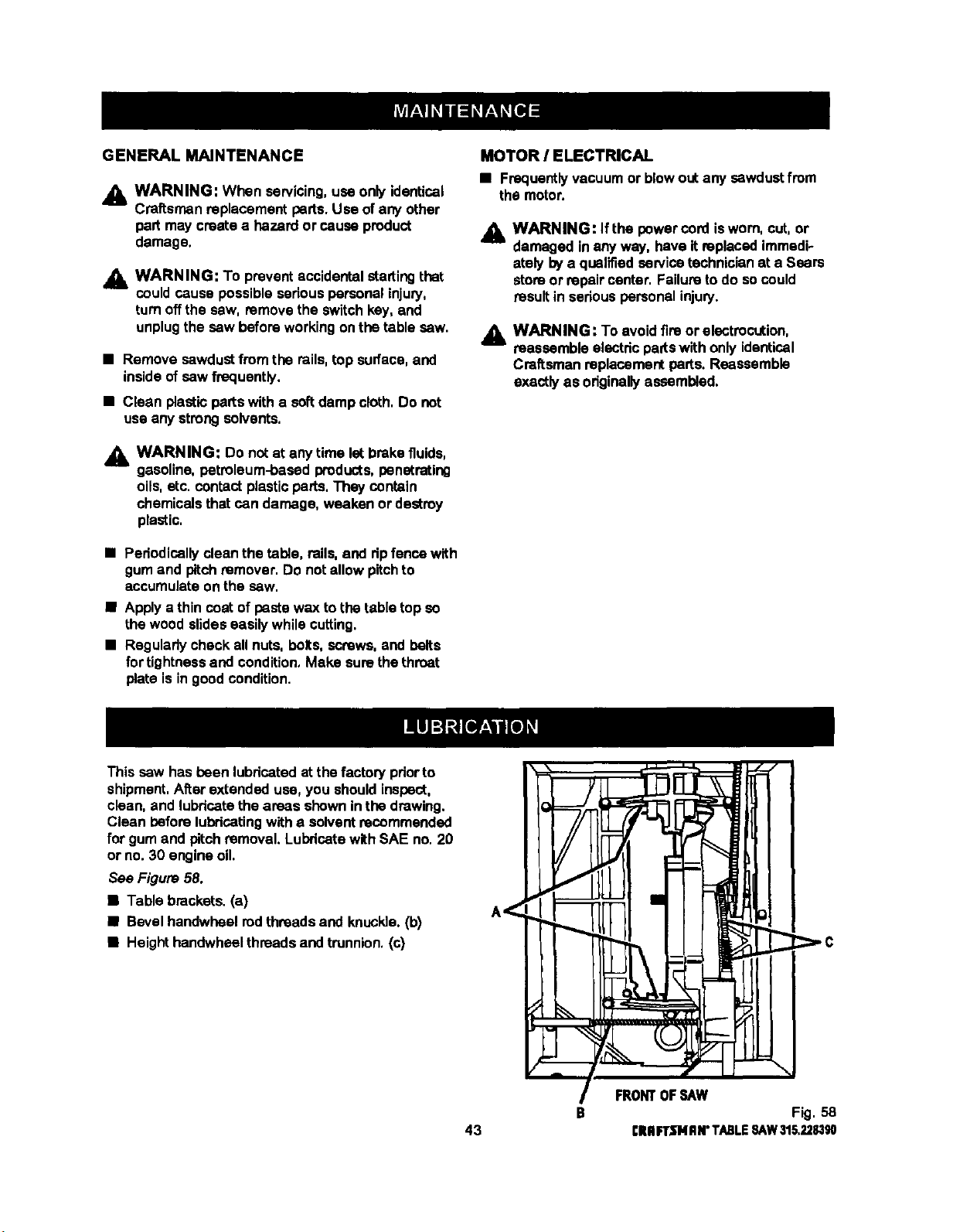
GENERAL MAINTENANCE
_1, WARNING: When servicing,use onlyidentical
Craftsman replacement parts.Use ofany other
pert may createa hazard or causeproduct
damage,
_1= WARNING: To preventaccidentalstartingthat
could cause possibleseriouspersonalinjury,
turn offthe saw, remove the switchkey, and
unplugthe saw beforeworkingonthe table saw.
• Remove sawdustfrom the rails,top surface,and
inside ofsaw frequently,
• Clean plasticparts with a softdamp cloth,Do not
useany strongsolvents.
_i, WARNING: Do not at any time let brakefluids,
gasoline, petroleum-basedproducts,penetrating
oils, etc. contactplasticparts,They contain
chemicalsthat can damage, weaken or destroy
plastic,
• Pedodically clean the table, rails, and dp fencawith
gum and pitch remover. Do not allow pitch to
accumulate on the saw.
• Apply a thin coatof paste wax to the table top so
thewood slideseasilywhile cutting.
• Regularlycheck all nuts,bolts, screws,andbelts
fortightnessand condition.Make sure thethroat
plate is in goodcondition.
MOTOR / ELECTRICAL
• Frequentlyvacuum or blowout any sawdustfrom
the motor.
,_k WARNING: If the powercordisworn, cut, or
damaged inany way, have it replacedimmedi-
ately bya qualifiedservicetechnicianat a Sears
store or repair center. Failureto do socould
result in sedous personalinjury.
WARNING: To avoidfire or electrocution,
reassembleelectdc partswith onlyidentical
Craftsman replacementparts. Reassemble
exactlyas originallyassembled.
This saw has been lubricatedat the factory pdorto
shipment,After extended use, you shouldinspect,
clean, and lubricatetheareas shownin the drawing.
Clean beforelubricatingwitha solventrecommended
for gum and pitchremoval. Lubricatewith SAE no,20
or no. 30 engine oil
See Figure 58.
• Table brackets.(a)
• Bevel handwheelrodthreadsand knuckle.(b)
• Heighthandwheelthreadsand trunnion,(c)
43
B
FRONTOF_L,_W
Fig. 58
CRIIFTSNRN"TABLESAW315.228,1_
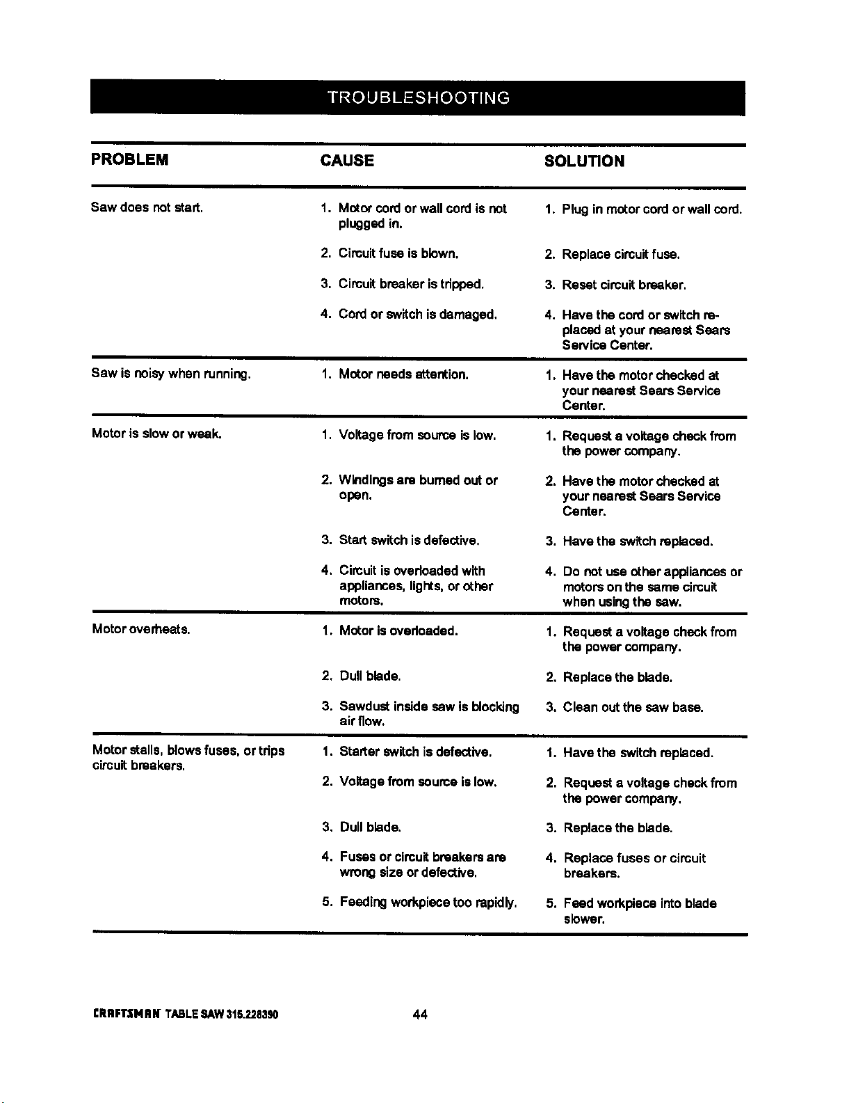
PROBLEM CAUSE SOLUTION
Sawdces notstart. 1. Motor cordorwallcord isnot 1. Plug in motorcord orwallcord.
pluggedin.
2, Circuitfuse is blown. 2.
3, Circuitbreakeristdpped. 3.
4, CON or switchis damaged. 4.
Saw isnoisywhen running.
Motoris slowor weak.
Motoroverheats.
Motor stalls,blowsfuses, or tdps
circuitbreakers.
1. Motor needsattention.
1. Voltage from sourceislow.
2. Windingsare bumad out or
open.
3. Start switchisdefective,
4. Circuitis ovedoadedwith
appliances,lights,or other
motors.
1. Motor isovedcaded.
2, Dull blade.
3. Sawdust insidesew is blocking
air flow.
1. Starter switchisdefective.
2. Voltagefrom seume islow.
3, Dull blade.
4. Fuses or circuitbreakersare
wrong size or defective,
5. Feeding workplacetoo rapidly.
1,
1.
2.
3,
4,
1.
2.
3.
Replace circuitfuse.
Reset circuitbreaker,
Have the cordor switch re-
placedat yournearest Sears
Sen/ice Center,
Havethe motorchecked at
yournearest Sears Service
Center.
Requesta voltagecheckfrom
the powercompany.
Have the motorchecked at
your nearest Sears Service
Center.
Have the switchreplaced.
Do not use otherappliancesor
motorson the same circuit
when usingthe sew.
Requesta voltage checkfrom
the powercompany.
Replace the blade.
Clean out the saw base.
1. Have the switch replaced.
2. Request a voltage checkfrom
the powercompany,
3. Replace the blade.
4. Replace fuses or circuit
breakers.
5. Feed workplace intoblade
slower.
CRRFI"$NIIN TABLESAW31&2283_ 44
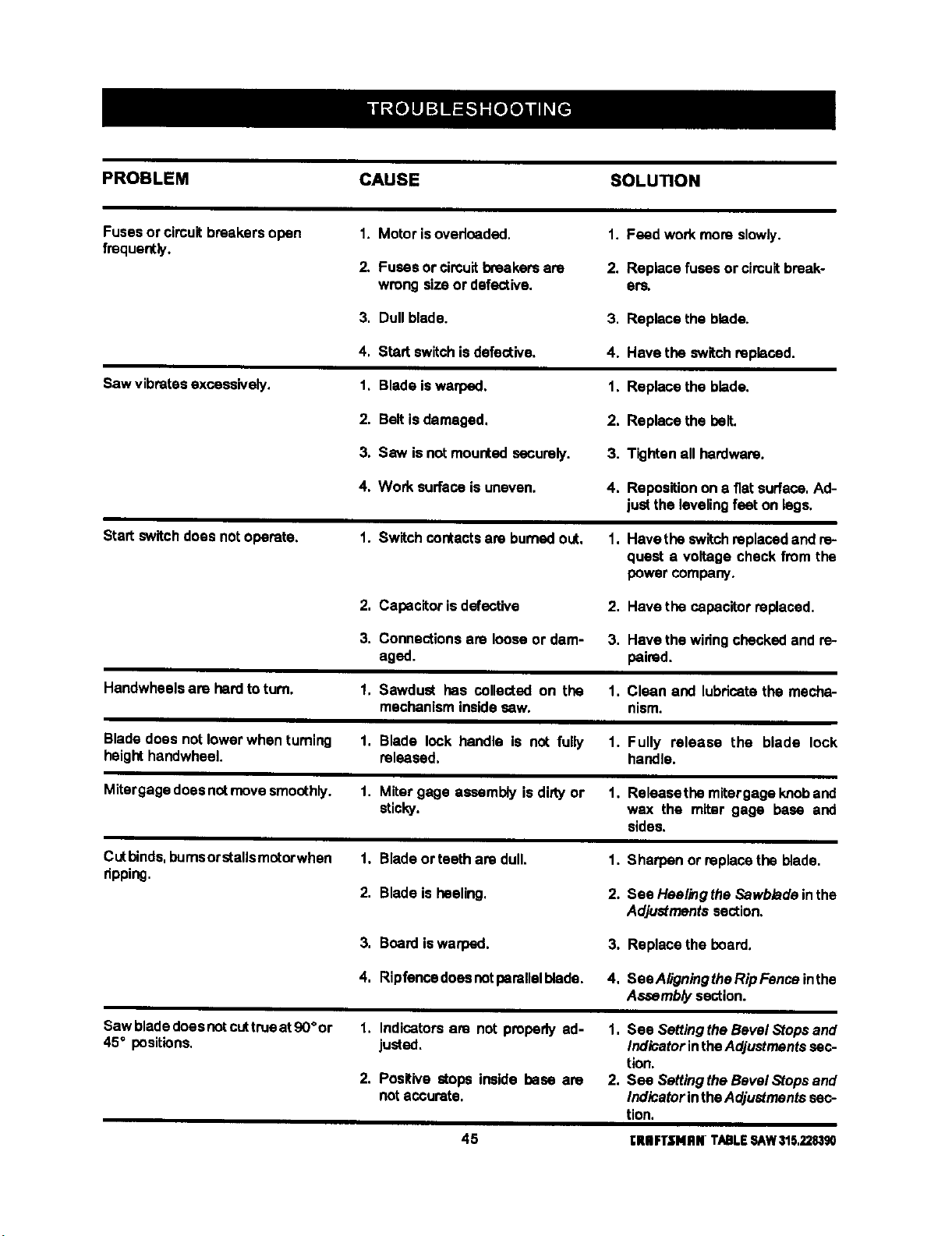
PROBLEM CAUSE SOLUTION
Fusesor circuitbreakers open
frequently.
1. Motor isovedceded.
2. Fuses orcircuitbreakersare
wrong size or defective.
I. Feed work more slowly.
2. Replace fuses or circuit break-
era,
3. Dull blade. 3. Replace the blade.
Saw vibratesexcessively.
4, Startswitchisdefective,
1, Blade iswarped.
4. Have the switchreplaced.
1, Replace the blade.
2. Belt isdamaged.
2. Replace the belt.
3. Saw isnot mounted securely. 3. Tightenall hardware.
4, Work surface is uneven.
4. Repesitionon a fiat surface.Ad-
just the levelingfeet on legs.
Startswitch does notoperate.
1. Switch contacts are burned out, 1. Have the switch replaced and ra-
quest a voltage check from the
power company.
2, Capacitorisdefective
2, Have the capacitorreplaced,
3. Connectionsare loose or dam- 3. Have the widngchecked and ra-
aged. paired.
Handwheelsare herd toturn.
1, Sawdust has collected on the 1. Clean and lubdoatethe mecha-
mechanisminsidesew. nism.
Blade does notlower when turning
height handwheel.
1. Blade lock handle is not fully 1. Fully release the blade lock
released, handle.
Mitergage doesnotmovesmoothly.
1. Miter gage assembly isdirtyor 1, Raleasethe mitergage knoband
sticky, wax the miter gage base and
sides.
Cutbinds,bumsorstalls motorwhen
ripping.
1, Blade orteeth are dull.
2. Blade is heeling,
1. Sharpen or raplasethe blade.
2. See Heelingthe Sawbladeinthe
Adjustmentssection,
3. Board iswarped. 3. Raplacethe board.
4, Ripfencedoeenotperallalblede. 4, SeaAligningtheRipFenoaintha
Assembly section.
Saw bladedoesnotcuttrueat 90°or
45° positions.
1. Indicators are not properly ad-
justed.
2. Positive stops inside base are
notaccurate.
1, See SettingtheBevel Stopsand
IndicatorintheAdjustmentssec-
tion.
2. Sea SettingtheBevel Stops and
IndicatorintheAdjustmentssec-
tion.
45 I:IUlFTSHRN TABLESAW315,2283_
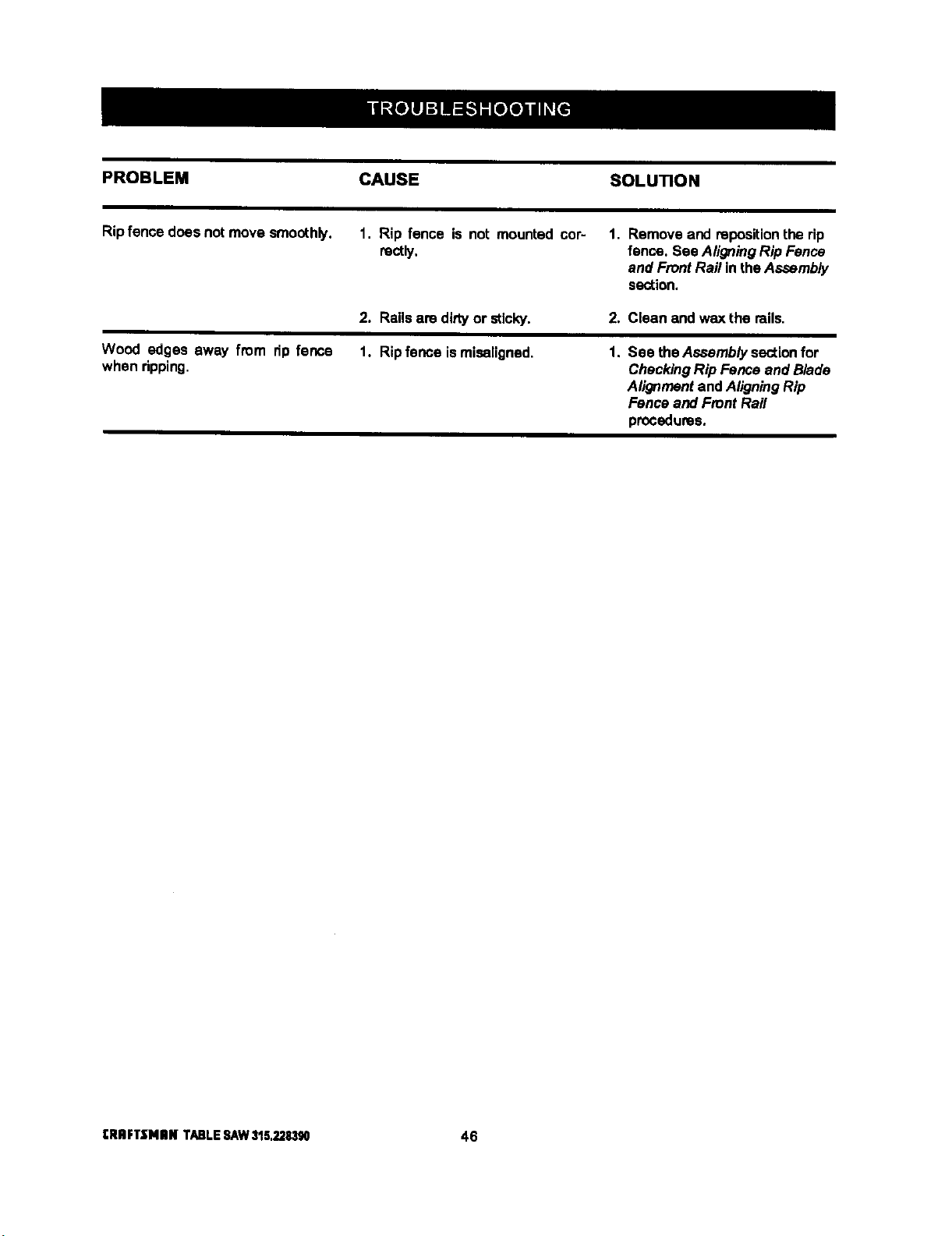
PROBLEM CAUSE SOLUTION
Ripfence does notmove smoothly. 1. Rip fence is not mounted cor-
rootly.
1. Remove and repositionthe dp
fence. See AligningRip Fence
and Front Rail intheAssembly
section.
Wood edges away from dp fence
when dpping.
2. Railsare dirtyor sticky.
1. Ripfence ismisaligned.
2. Clean and wax the mils.
1. See theAssemblysectionfor
CheckingRip Fence and Blade
Alignmentand AligningRip
Fence and Front Rail
procedures.
rRRFTSNIIH TABLESAW$15,2283g0 46

47 CRIIFTSMRNTABLESAW315.228390

