
Loading ...
Loading ...
Loading ...
18 19
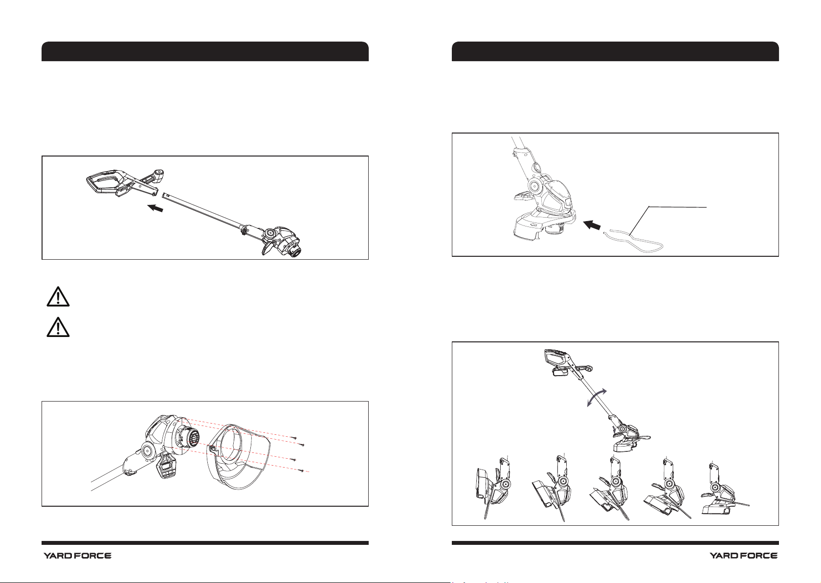
Assembling the Flower protector (Fig 5)
The Flower protector is designed to protect owers, trees and garden furniture and so on,
which stay in your cutting area.
1. Align the ower protector with corresponding slot on the head of the device.
2. Push it in; Make sure that it sits in place securely.
Flower protector
Fig 5
Adjusting the operating angle of the cutting head (Fig 6)
The cutting head of this device can be stop in 5 positions in quick manner.
1. Depress the pedal board with your foot. Meanwhile, tilt the operating bar.
2. When it gets close to required position, release your foot from the pedal board,
3. Keep moving, the tongue of pedal board will fall into required position. At this moment,
the cutting head has been xed at new angle.
Fig 6
90
o
60
o
45
o
30
o
0
o
Step 1
Step 2
Assembling the rear housing (Fig 3)
Insert the pole into the rear housing. Before inserting, make sure the front handle is on the
same side with the black cover of the power head. Then push hard the pole into the handle,
when hear a click, the installation is completed. To make sure the pole has been inserted in
the correct position, please check if the red arrow on the pole is just pointing the edge of
upper handle.
Fig 3
Assembling the safety guard (Fig 4)
WARNING! The safety guard must be properly installed. The safety guard
provides partial protection from the risk of thrown objects to the operator and
others.
WARNING! If safety guard is not properly installed, damage to unit (including
motor failure) will be result.
1. Remove four mounting screws from motor housing.
Note: They are pre-mounted on the motor housing by factory to help end-user nd them
quickly. And send a message to end-user, where these four screws should be used for.
2. Fit the safety guard onto the motor housing.
3. Fix the safety guard in place by using four screws.
Fig 4
ASSEMBLY
SAFETY INFORMATION
ASSEMBLY
Loading ...
Loading ...
Loading ...