Loading ...
Loading ...
Loading ...
SERVICE AND ADJUSTMENTS
WARNING: TO AVOID SERIOUS INJURY, BEFORE PERFORMING ANY SERVICE OR ADJUST-
MENTS:
• Depress clutch/brake pedal fully and set parking brake.
• Place motion control lever in neutral (N) position.
• Place attachment clutch in "DISENGAGED" position.
• Turn ignition key to "STOP" and remove key.
• Make sure the blades and all moving parts have completely stopped,
• Disconnect spark plug wire from spark plug and place wire where it cannot come in contact
with plug,
TRACTOR
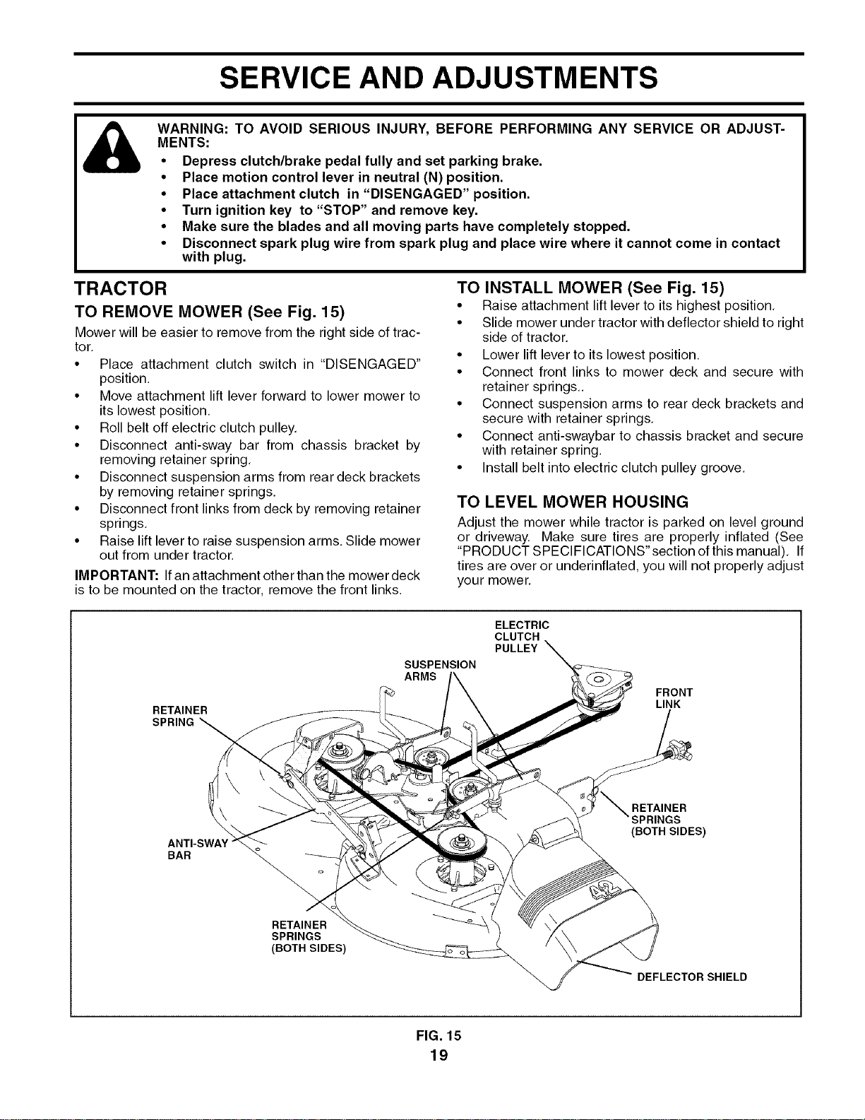
TO REMOVE MOWER (See Fig. 15)
Mower will be easier to remove from the right side of trac
tor
• Place attachment clutch switch in "DISENGAGED
position
• Move attachment lift lever forward to lower mower to
its lowest position
• Roll belt off electric clutch pulley
• Disconnect antisway bar from chassis bracket by
removing retainer spring
• Disconnect suspension arms from rear deck brackets
by removing retainer springs
• Disconnect front links from deck by removing retainer
springs
• Raise lift lever to raise suspension arms Slide mower
out from under tractor
IMPORTANT: If an attachment other than the mower deck
is to be mounted on the tractor remove the front links
TO INSTALL MOWER (See Fig. 15)
• Raise attachment lift lever to its highest position
• Slide mower under tractor with deflector shield to right
side of tractor
• Lower lift lever to its lowest position
• Connect front links to mower deck and secure with
retainer springs
• Connect suspension arms to rear deck brackets and
secure with retainer springs
• Connect anti swaybar to chassis bracket and secure
with retainer spring
• Install belt into electric clutch pulley groove
TO LEVEL MOWER HOUSING
Adjust the mower while tractor is parked on level ground
or driveway Make sure tires are properly inflated (See
'PRODUCT SPECIFICATIONS section of this manual) If
tires are over or underinflated, you will not properly adjust
your mower
RETAINER
SPRING
SUSPENSION
ARMS
ELECTRIC
CLUTCH
PULLEY
FRONT
LINK
BAR
RETAINER
SPRINGS
(BOTH SIDES)
RETAINER
SPRINGS
(BOTH SIDES)
DEFLECTOR SHIELD
FIG. 15
19
Loading ...
Loading ...
Loading ...