Loading ...
Loading ...
Loading ...
Millbrook House, Grange Drive, Hedge End, Southampton, SO30 2DF
0844 879 3587
dimplex.co.uk | gdcgroup.co.uk
40
NOTE: If the heat pump is in heating “ON” mode and the maximum outside temperature is reached,
the heat pump will revert to and maintain the set back temperature until the heating is turned off and
on again. To prevent this, it is recommended to set your summer temperature (see heat curves section
4.4.12), at a higher value (the default outside ambient setting is 18°C).
4.4.13 Comfort level
For end-users, the preferred method of modifying the heating system comfort level is by using the comfort
level function rather than modifying the heat curve. Here, it is possible to raise or lower the water input
temperature within a range of 9K (-3 to +6) by accessing the comfort level.
For more information please see the A-Class User Manual
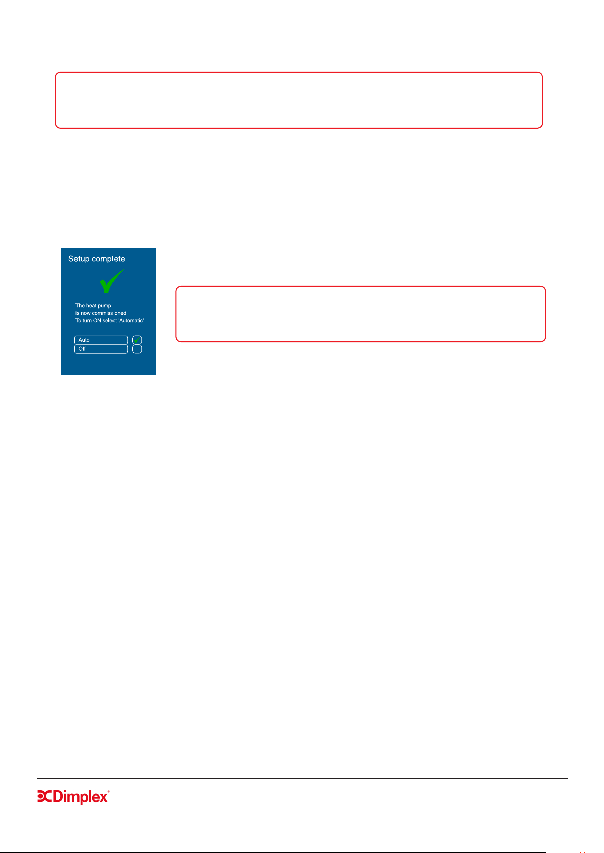
4.4.14 Setup complete
NOTE: To complete commissioning and allow the heat pump to operate, you
must select the ‘Setup complete’ submenu in the installer menu, as shown in
gure 33. if you do not see this screen, commissioning has not been successful
and the heat pump will not operate correctly.
Once all of these steps have been carried out successfully, you will see the
screen shown in gure 33.
Figure 33: Setup complete
Selecting Auto will activate all settings, where as selecting Off will enable the heat pump only to carry out
frost protection (i.e. no heating is required but the heat pump is protected from freezing conditions).
The default setting for the heat pump is Off. To turn on the heat pump, you must return to the home screen
to access the user menu.
For further information on end user controller instructions please see A-Class Air Source Heat Pump User
Guide supplied in the hydraulics pack.
4.5 Additional Installer Menu Options
Once the commissioning process has been completed, additional menus will be available to the installer,
as outlined in this section. These options must be accessed through the service menu.
4.5.1 Service menu
The service menu can be accessed, in a similar manner to the installation menu, by inputting the installer
menu code (22) and then using the ’Login’ access code 998. Access to this menu may be required for fault
nding or servicing.
4.5.2 Message log
The message log menu provides a list of all errors that have taken place, including the date and time when
they occurred. Selecting an individual error code will provide more information on the type of error that
occurred if an SD card is present. Active error messages will show a ticked box.
Loading ...
Loading ...
Loading ...