Loading ...
Loading ...
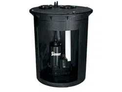
Installation Instructions.
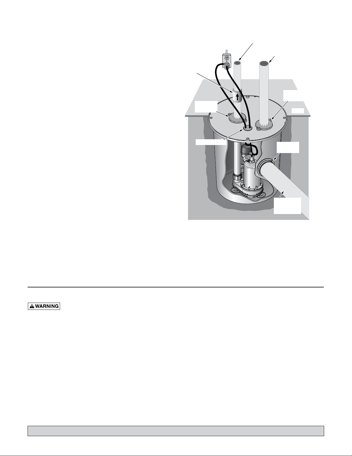
1. Dig the hole for the basin and the sub-base. The hole
must be deep enough so the top of the basin is flush with
the finished floor.
NOTICE: The sub-base should include 4” of sand or
gravel. The maximum diameter of rock should be 1/2”; 3/4”
maximum diameter pea gravel is recommended.
2. Level the sub-base out until it is smooth. Sharp rock can
damage the basin.
3. Reach into the inlet hole to retrieve the hardware kit.
Locate the cord grommet in the hardware kit.
4. Reach into the inlet hole again to pull the power cords
up through the cord grommet hole in the cover. Press
the cords into the cord grommet and install the grommet
in the cover.
5. Locate the inlet hub in the hardware kit, and snap it into
the inlet hole.
6. Install the basin on top of the sub-base.
7. Insert a 4” inlet pipe through the inlet hub. Insert it 2”
into the basin. Dish soap can be used to lubricate the
inlet hub. If necessary, file the sharp edges of the pipe to
prevent damage to the hub.
NOTICE: The inlet pipe should pitch down to the basin
inlet at 1/4” per foot. This will cause the water to run into
the basin.
8. Backfill around the basin with crushed rock, with a
maximum diameter of 1/2”, or use pea gravel.
9. Install a 1-1/2” discharge pipe into the 1-1/2” discharge
flange.
10. Install a 2” vent pipe into the vent flange. The vent pipe
must go through the roof of the building or it can be
connected to an existing vent pipe. The sump basin
must be vented.
NOTICE: Proper ventilation is needed to prevent
negative basin pressure and to provide air within the
basin.
11. Install a 1-1/2” check valve in the discharge pipe. Make
certain the flow indicating arrow points away from the
pump. This check valve will keep the water from running
back into the basin when the pump is not running.
NOTICE: To prevent pump contamination, clear basin
of any debris during or after installation.
12. Plug the pump into a properly grounded outlet.
13. Check the operation by filling the basin with water and
observing pump operation through one complete cycle.
Make sure no parts of the assembly interfere with the float.
OPERATION
Failure to make this operational check may
lead to improper operation, premature failure, and flooding.
NOTICE: The shaft seal depends on water for lubrication
and cooling. Do not operate the pump unless it is submerged
in water as the seal may be damaged if allowed to run dry.
Allowing the pump to run dry will void the warranty.
An automatic overload protector in the motor will protect
the motor from burning out due to overheating/overloading.
When the motor cools down, the overload protector will
automatically reset and start the motor.
If the overload trips frequently, check for the cause. It could
be a stuck impeller, wrong/low voltage, or an electrical failure
in the motor. If an electrical failure in the motor is suspected,
have it serviced by a competent repairman.
The pump is permanently lubricated. No oiling or greasing is
required.
NOTICE: The pump will not remove all water. For extended
operation, water depth must be at least 5” (13 cm) to prevent
motor overheating.
Airlocks
When a pump airlocks, it runs but does not move any water.
An airlock will cause the pump to overheat and fail. The
discharge pipe is plumbed with a predrilled anti-airlock hole.
Leakage from the anti-airlock hole is normal during pump
operation.
Float Switch – Operational Check
1. Fill the sump with the correct amount of water to check
the operation and tightness of the connections. During
the first automatic cycle, it may take 30 seconds or more
before the pump is primed and pumping. The pump will
start as indicated in the “Pump, Motor, Switch and Cord
Specifications” table on Page 2.
2. Check the turn-off position. The pump will stop
approximately as indicated in the “Pump, Motor, Switch
and Cord Specifications”.
3. If the pump does not operate, check the electrical service.
3
For parts or assistance, call Simer Customer Service at 1-800-468-7867 / 1-800-546-7867
5596 0407
4" Inlet Pipe
Slope @ 1/4"
Per Foot
4" Snap-in
Inlet Hub
Cord Grommet
Discharge
Flange
Vent
Flange
Floor
1-1/2" Discharge
Pipe
Vent Pipe – Extend vent
through roof or connect
to existing vent.
Plug the Float Switch
into a Properly
Grounded Outlet.
Check Valve
Purchase check valve and inlet, vent
and discharge pipes locally.
Figure 1 – Typical Installation
Loading ...
Loading ...
Loading ...