Loading ...
Loading ...
Loading ...
E-3
English
5.1
Standards
The CTHK screw-in heaters are VDE certified and meet the
requirements of the following standards/guidelines:
DIN EN 60335-1
DIN VDE 0700-253
DIN EN 60529, degree of protection IP54
DIN 1988 technical regulations for
drinking water installations (TRWI)
EU directive 2006/95/EC (low voltage directive)
EU directive 1935/2004/EC (contact with food)
EU directive 97/23/EC (pressure equipment directive)
The plastic material of the connection casing fulfils the
requirements of § 5 Subsection 1 of the German foodstuffs and
consumer goods law and the recommendations of the German
federal office of consumer protection and food safety (KTW
certification).
5 Assembly, installation
and safety instructions
5.1 General installation and safety
instructions
ATTENTION!
Installation of the heating element and initial start-up must only be
performed by a qualified technician! Improper installation will void any
warranty claims.
The CTHK screw-in heaters must be installed by a technician in
adherence with the valid standards and installation regulations.
The following regulations must be adhered to:
The German Electrical Engineers’ Association (VDE)
stipulations and the regulations of the local utility company
The heating installation regulation (HeizAnl.V)
When used in pressure vessels: The AD instruction sheet
(workgroup pressure vessels) A3, Section 3.28
The DIN 1988 series standards
For closed water heaters, the arrangement of the fittings and
safety devices used must always be observed (acc. to
country-specific standards).
During operation, the electric heating element and the sensor
pipe must be completely immersed in water. The heat-induced
flow of water must not be obstructed.
The screw-in heater has a safety temperature limiter to prevent
further heating of the device when the water has reached a
maximum temperature of 95°C. According to DIN EN 60335-2-
21, the maximum water temperature may be up to + 20°C higher
(
⇒115°C) and thereby also has an influence on all the other
"components and installations" in the heat distribution system
and the generator circuit!
NOTE
When using a pressure relief system, it must be ensured that water is
able to drip from the outlet pipe of the pressure relief system, and this
pipe must be left open to the outside atmosphere; · the pressure relief
system must be operated regularly in order to remove limescale deposits
and to ensure that it is not blocked; an outlet pipe connected to the
pressure relief system at a constant downward angle must be installed in
a frost-free area.
Care must be taken to ensure that, in the event of a temperature
controller malfunction, the connection components (connection
pipes, safety valve combinations, etc.) will withstand the max.
possible controller temperature (according to the standard) and
further damage will be prevented.
In the case of very hard water, formation of limescale will limit the
function. Adequate measures must be taken, such as reducing
the temperature, installing a water softening system, or regularly
removing the limescale.
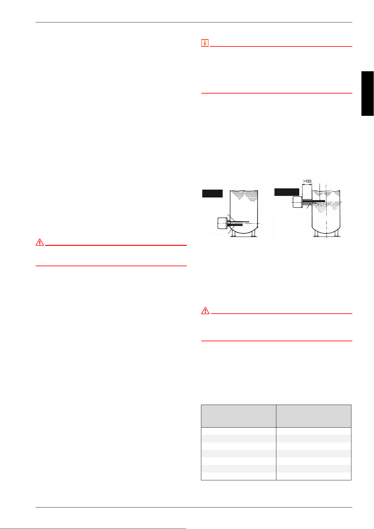
Mounting position:
In order to ensure that temperature sensor and heating element
reach far enough into the boiler, the R 1 ½" connecting sleeve of
the cylinder must not be longer than 130 mm.
In order to heat the entire contents of the boiler uniformly, the
screw-in heater should be installed as far down in the boiler as
possible.
A minimum distance (installation length + 100 mm) must be
maintained in front of the connecting sleeve for mounting, etc.
ATTENTION!
During installation make sure that the immersion pipe (temperature
sensor) is installed in the correct position. The immersion pipe must
always be mounted above (1 phase) or above and between (3 phases) the
heating element(s)!
Recommended fluid amounts
See the following table for the amount of fluid to be heated in
relation to the power consumption (acc. to VDE 0700 Part 73 §
7.12.1).
The specified amounts are minimum amounts. Deviations are
possible depending on the application. Tubular heating elements
must always be covered by a sufficient amount of fluid.
Nominal power
consumption
(W)
Amount of fluid (approx.)
(litres)
2000 5
3000 8
4500 12
6000 16
7500 20
9000 24
12000 32
&RUUHFW
,QFRUUHFW
7HPSHUDWXUHFRQWUROOHU
+HDWLQJHOHPHQW
7HPSHUDWXUH
FRQWUROOHU
+HDWLQJHOHPHQW
)ODQJHIUDPHWRRORQJ
DQGZHOGHGLQWRRKLJK
7HPSHUDWXUHFRQWUROOHU
XQGHUQHDWKKHDWLQJHOHPHQW
IULJLG]RQH
Loading ...
Loading ...
Loading ...