Loading ...
Loading ...
Loading ...
4. Remove the liner from its packaging and place the back of the liner on the floor or countertop
in front of the wall where it will hang. Save the trim kit and hardware for step 10.
5. With the liner on its back facing you, remove the shield(s) and blower housing(s) as follows:
a) Remove the shipping tape that is securing the blower shield(s) inside the liner.
b) Remove the shield(s) by lightly pulling it (lifting it) toward the front of the liner.
c) Gently close the back draft damper(s) from the top side of the liner.
d) To remove the blower housing(s), unsnap the suitcase latches (one on each side of the
housing).
e) Support the housing and lift it away from the blower base, then tip it back toward you to
clear the blower wheel(s), and then lift it up and out from the liner.
Make sure power is off at the supply panel / breaker during service or
installation.
6. One blower motor must be removed from each blower assembly to access the connection
box(es). The blower assembly will have a decal identifying the location of the connection
box(es). It is not necessary to remove the blower wheel from the motor.
a) Remove the three screws retaining the blower motor.
b) Pull the motor out far enough so you can reach its electrical connector.
c) Unplug the connector, set the blower motor and screws aside.
• To lighten the liner for easier handling, the remaining motor(s) can be removed as well, in the
same manner as above.
7. WIRING PREPARATION:
a) Install an appropriate 1/2” UL listed electrical wire clamp through each motor box electrical
opening on top of the liner.
b) Install electrical wiring from the service panel to the liner location for each motor box.
Consult the connection diagrams (on previous page) for further details on electrical
placement. See “ELECTRICAL SUPPLY AND GROUNDING” on page1 for power
requirements.
Electrical (2
)
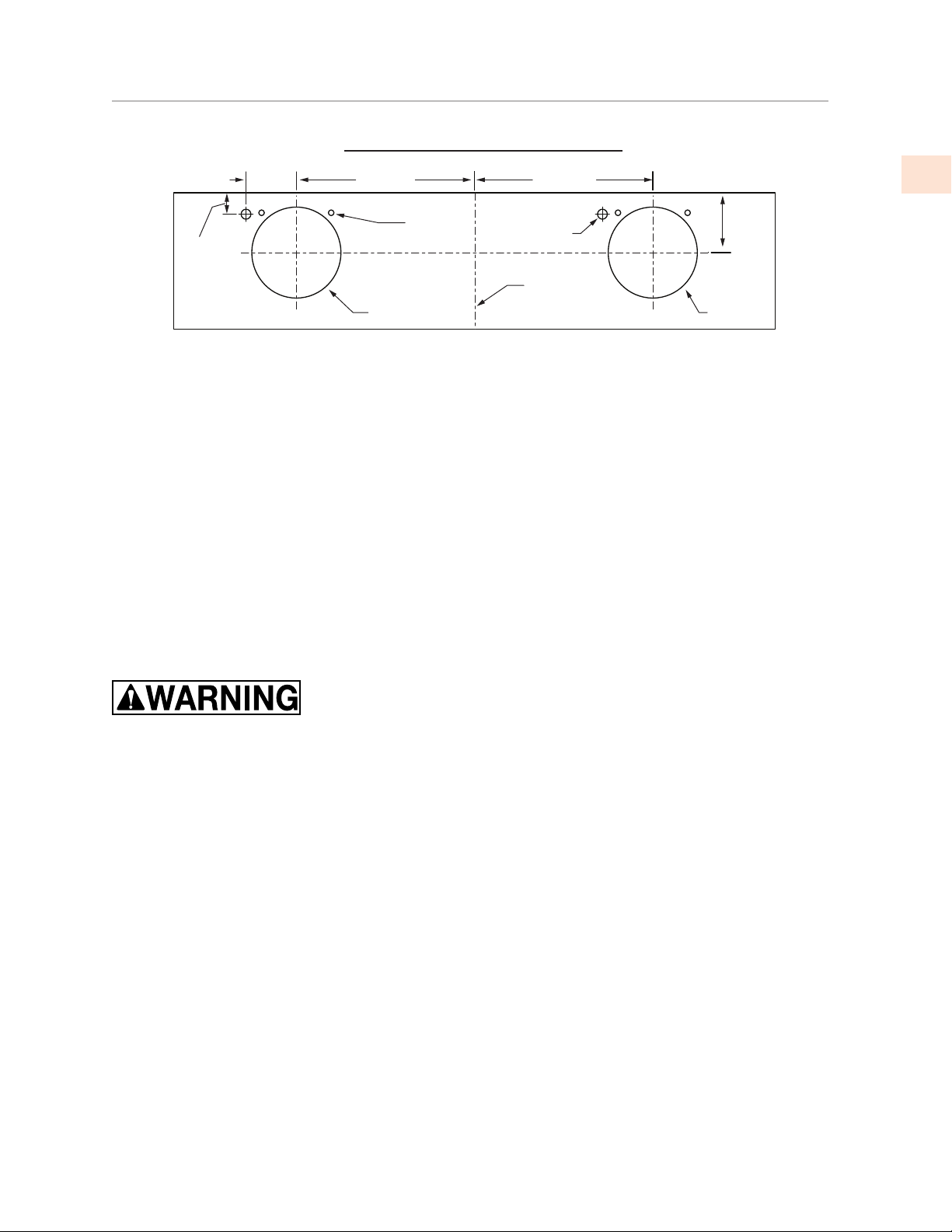
Connection diagram (48”- 54” widths)
Two WM2L Dual blowers (1200 CFM)
(Top view)
Wall side
Centerline
of liner
Motor
cooling
vent (4)
8"
[20.3 cm] Round
5-1/2"
[14 cm]
1-3/4"
[4.4 cm]
5-1/4"
[13.3 cm]
11"
[29.9 cm]
11"
[29.9 cm]
8"
[20.3 cm] Round
INSTALLATION
(CONT.)
©2019 Hestan Commercial Corporation
13
EN
Loading ...
Loading ...
Loading ...