Loading ...
Loading ...
Loading ...
4
INSTALLATION OPTIONS
Read this entire manual before you install and use your pellet stove. Failure to follow instructions may result
in property damage, bodily injury, or even death! See specic installation details for clearances and other
installation requirements.
Freestanding Unit - supported by pedestal/legs and placed on a non-combustible oor surface in compliance
with clearance requirements for a freestanding stove installation.
Alcove Unit - supported by pedestal/legs and placed on a non-combustible oor surface in compliance with
clearance requirements for an alcove installation.
Your pellet stove may be installed to code in either a conventional or mobile home (see Special Mobile Home
Requirements). It is recommended that only a authorized technician install your pellet stove, preferably an NFI
certied specialist. DO NOT CONNECT THIS UNIT TO ANY AIR DISTRIBUTION DUCT OR SYSTEM. The use of other
components other than stated herein could cause bodily harm, heater damage, and void your warranty.
IMPROPER INSTALLATION: The manufacturer will not be held responsible for damage caused by the malfunction
of a stove due to improper venting or installation. Call (800) 750-2723 and/or consult a professional installer if
you have any questions.
Installation
CLEARANCES
Your pellet stove has been tested and listed for installation in residential, mobile home, and alcove applications
in accordance with the clearances given. For safety reasons, please adhere to the installation clearances and
restrictions. Any reduction in clearance to combustibles may only be done by means approved by a regulatory
authority.
INSTALL ALL VENTS AT CLEARANCES SPECIFIED BY THE VENT MANUFACTURER
When this unit is being installed on a combustible oor it is mandatory that a 1/2” (13 mm) thick non-combustible
hearth pad be installed under the heater. The non-combustible hearth pad must extend at least 6” (152 mm)
beyond the fuel loading and ash removal openings and at least the depth of the heater plus 6” (152 mm) out in
front of the heater. The oor protector must extend 2” (51mm) beyond each side of the exhaust vent. This applies
to both freestanding heaters and insert heaters.
BACK WALL
Figure 5
Figure 6
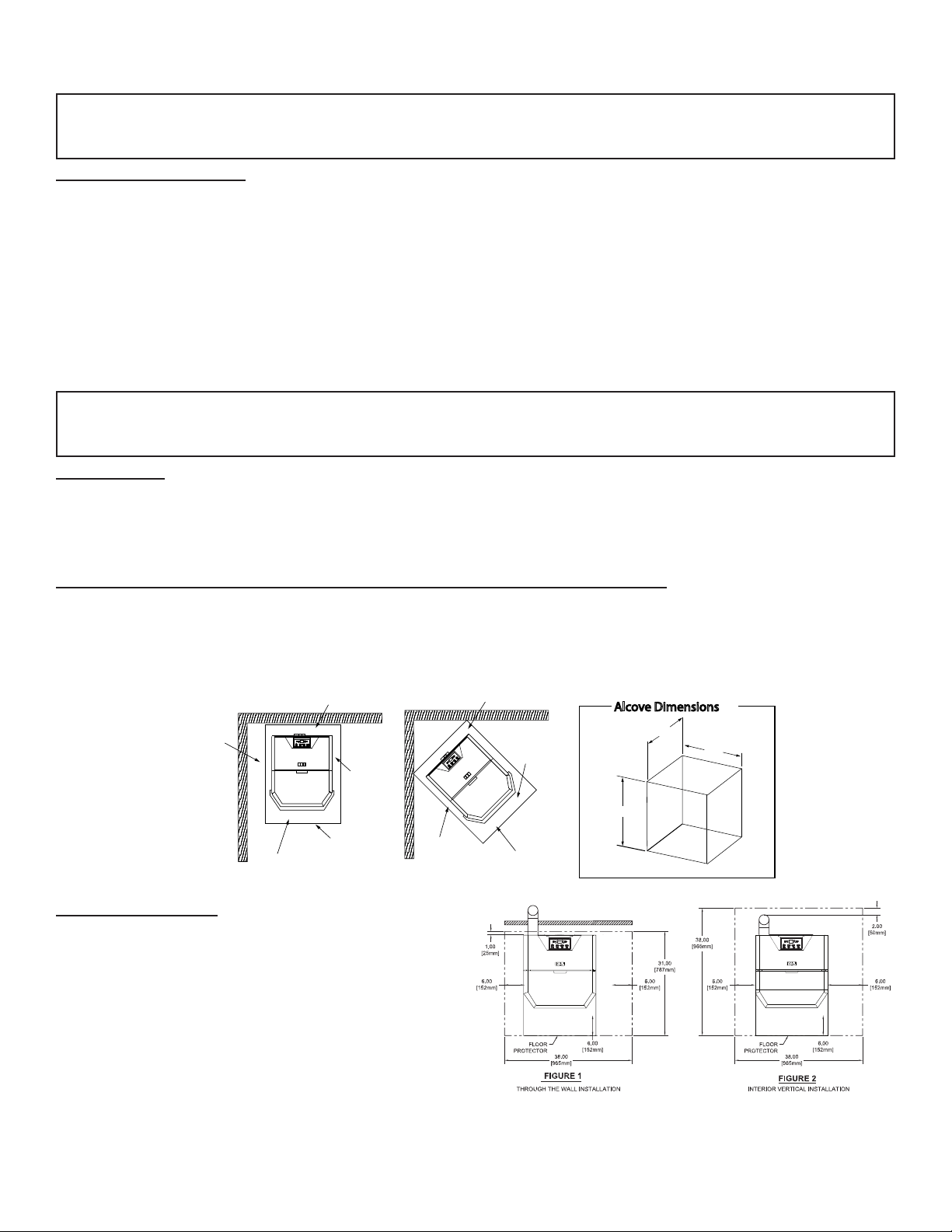
Alcove Dimensions
36”
35”
40”
2”
6”
USA 6”
CANADA 8”
FLOOR PROTECTION
USA 6”
CANADA 18”
2”
FLOOR
PROTECTION
USA 6”
CANADA 8”
USA 6”
CANADA 18”
BACK WALL
Figure 5
Figure 6
Alcove Dimensions
36”
35”
40”
2”
6”
USA 6”
CANADA 8”
FLOOR PROTECTION
USA 6”
CANADA 18”
2”
FLOOR
PROTECTION
USA 6”
CANADA 8”
USA 6”
CANADA 18”
BACK WALL
Figure 5
Figure 6
Alcove Dimensions
36”
35”
40”
2”
6”
USA 6”
CANADA 8”
FLOOR PROTECTION
USA 6”
CANADA 18”
2”
FLOOR
PROTECTION
USA 6”
CANADA 8”
USA 6”
CANADA 18”
FLOOR PROTECTION
This heater must have a non-combustible oor
protector (ember protection) installed beneath it if the
oor is of combustible material. If a oor pad is used,
it should be UL listed or equal. The oor pad or non-
combustible surface should be large enough to cover
at least the area under the product and 6” (152 mm)
beyond the front and beyond each side of the fuel
loading and ash removal openings. Floor protection
must extend under and 2“ (51 mm) to each side of
the chimney tee for an interior vertical installation.
Canadian Installations require a minimum of 450 mm
[17.7”] beyond the front of the unit and 200 mm [7.8”]
beyond each side of the unit. A Floor Protector of 1/4”
thick is recommended for this installation.
Attention: DO NOT vent under any porch, deck, awning, or in any semi enclosed or roofed area. Doing so may
result in unpredictable airow at the vent cap under certain conditions and can affect the performance of
your stove, as well as, other unforeseeable issues.
Loading ...
Loading ...
Loading ...