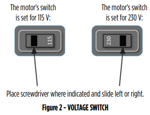
To change the pump voltage from the factory setting of 115 Volts, a qualified electrician should:
1. Disconnect power supply to pump
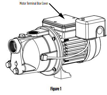
2. Remove the cover from the motor terminal box
3. Slide the voltage switch from 115 V to 230 V, as shown in Figure 2
4. Reassemble the terminal box cover
QUICK INSTALLATION GUIDE (Replacing an Existing Pump)
This quick installation guide assumes you will be cutting the existing pump free from the plumbing.
More detailed instructions are provided in the Detailed Installation Instructions.
WARNING DO NOT RUN THE PUMP BEFORE PRIMING IT; THE SEAL AND IMPELLER COULD BE PERMANENTLY DAMAGED
1. Ensure power has been shut off at the breaker before proceeding.
2. This pump is dual voltage (115/230 V)! Inspect the voltage wiring on the pump and ensure it matches the voltage on the breaker before continuing with the installation (see Voltage Setting Instructions).
3. Completely relieve pressure from the water system before working on the water system. Open the faucet nearest the tank and allow the water to drain until the tank is empty.
4. Disconnect wiring from the pressure switch to the electrical source.
5. Using a hacksaw or reciprocating saw, cut all PVC piping as close to the old pump as possible at both the suction and discharge openings. Ensure the pipe from the well and the pipe from the tank are clean and free of any pipe shavings or pieces as these could get into the pump and damage the impeller.
6. Set the new pump in place.
7. Seal the threads on the suction opening on the pump with PTFE tape or thread compound and insert the 1-1/4" male galvanized adapter into the suction opening. Tighten securely but do not over-tighten as this could crack the fitting.
8. Attach the 1-1/4" PVC pipe from the well to the male adapter (additional fittings may need to be added). Check to ensure the joints are airtight. Even a pinhole can prevent proper operation of the pump.
9. Seal the threads of the discharge opening on the pump with PTFE tape or thread compound and insert the 1" male PVC adapter into the discharge opening. Tighten securely but do not over-tighten as this could crack the fitting.
10. Attach the 1" PVC pipe from the tank to the 1" male PVC adapter (additional fitting may need to be added). Check to ensure the joints are airtight. Even a pinhole can prevent proper operation of the pump.
11. A pressure gauge is not supplied with the pump. It should be installed into the 1/8" NPT hole on the front of the casing on the opposite side of the pressure switch (see Typical Installations Figures 3, 4, 5, or 6).
12. An electrician should be employed to do the wiring and connect the electrical service to the pump (see Wiring Instructions).
13. Prime the pump (see Priming Instructions).
14. Verify everything has been completed using the Installation Checklist provided in this manual.
DETAILED INSTALLATION INSTRUCTIONS
WARNING DO NOT RUN THE PUMP BEFORE PRIMING IT; THE SEAL AND IMPELLER COULD BE PERMANENTLY DAMAGED
Before proceeding, ensure power has been shut off at the breaker. If this is replacing an existing pump, completely relieve pressure from the water system before working on the water system. Open the faucet nearest the tank and allow the water to drain until the tank is empty.
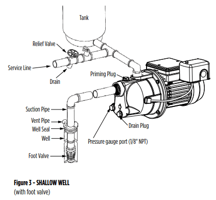
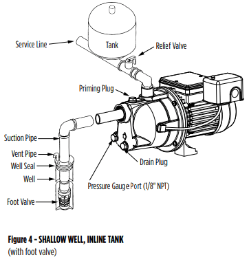
SHALLOW WELL APPLICATION (for pumping depths down to 25 ft [7.6 m])
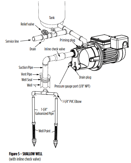
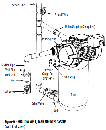
Shallow well installations use only a single pipe connecting the pump to the water supply. This pump can be used for drilled wells (see Figures 3, 4 or 6) or driven wells (see Figure 5). Drilled wells are holes drilled into the ground by professional well drillers using a large rig. Driven wells use well points (also known as sand points), which is a long pointed tube with a screen that allows water to enter the pipe but keeps out sand and sediment. The water level in a driven well is fairly high or near ground level (maximum 30 ft [9.1 m]). Continue with the appropriate shallow well installation.
DRILLED WELLS (with foot valve)
1. Measure from the bottom of the well to the top of the well and subtract 5 ft (1.5 m). This is the length of 1-1/4" rigid PVC pipe and couplings you will need from the bottom of the well to the first elbow. Cut the pipe and use a round file to smooth the pipe cutting. Ensure the pipe is clean and free of any pipe shavings or pieces as these could get into the pump and damage the impeller. The remainder of the pipe will be used to connect the pump to the well.
2. Attach the 1-1/4" male PVC adapter to one end of the rigid PVC pipe and attach the adapter to the foot valve. Check to ensure the joints are airtight. Even a pinhole can prevent proper operation of the pump.
3. Firmly clamp the unfinished end of the pipe with a pipe clamp 1 ft (30 cm) from the top of the pipe. This will prevent the pipe from dropping to the bottom of the well. Lower this section into the well foot valve first.
4. On the end protruding from the well, which is held in place with the pipe clamp, insert the well seal and have the pipe protrude 1 ft (30 cm) outside of the well seal. If you have measured correctly, the foot valve will be suspended 4 ft (1.2 m) from the bottom of the well. This will ensure sand and sediment doesn’t get drawn into the system. Install a well vent tube in the well cap.
5. Attach the end of the pipe securely to a 1-1/4" PVC 90° elbow.
6. Install the pump in a clean, dry, and ventilated location which provides adequate room for services and protection from freezing temperatures. It should be bolted to a good foundation, preferably concrete, and provided with adequate drainage. Locating the pump as close as possible to the water source reduces the friction in the suction pipe and will provide maximum performance.
7. A pressure gauge is not supplied with the pump. It should be installed into the 1/8" NPT hole on the front of the casing on the opposite side of the pressure switch (see Typical Installations Figures 3, 4 or 6).
8. Attach a 1-1/4" male galvanized adapter into the suction inlet. Do not over-tighten as this could crack the fitting.
9. Use the remainder of the PVC pipe from Step 4. Smooth the pipe cutting using a round file. Ensure the pipe is clean and free of any pipe shavings or pieces as these could get into the pump and damage the impeller; connect one end of the pipe to the adapter attached to the suction inlet. Check thoroughly for any leaks. All connections and joints must be airtight. A small pinhole leak can prevent the pump from operating properly.
10. Follow the Pump to Tank Installation procedures.
11. Verify everything has been completed using the Installation Checklist provided in this manual.
DRIVEN WELL (with check valve and well point)
1. Drive the well point into the ground according to the instructions that come with the well point. It must be deep enough to bore through the water bearing formation below the water table but should not exceed 25 ft (7.6 m) in depth. An individual well point may not supply the amount of water needed. Sometimes it is necessary to use more than one well point to increase the water supply. The two separate well points can be jointed together using additional piping and a cross joint (see Figure 5).
2. Plan to have at least 1 ft (30 cm) of pipe protruding from the ground. The rise pipe should be galvanized pipe in approximately 5 ft (1.5 m) sections. This makes it easier to hand drive. Use as much pipe and as many drive couplings as it takes to both reach the water and account for the 1 ft (30 cm) of pipe protruding from the ground.
3. Attach a 1-1/4" galvanized elbow onto the pipe protruding from the ground.
4. Attach a 1-1/4" galvanized nipple to the 1-1/4" galvanized elbow.
5. Attach a 1-1/4" check valve to the 1-1/4" galvanized nipple.
6. Attach a 1-1/4" male PVC adapter to the 1-1/4" check valve.
7. Install the pump in a clean, dry, and ventilated location which provides adequate room for services and protection from freezing temperatures. It should be bolted to a good foundation, preferably concrete, and provided with adequate drainage. Locating the pump as close as possible to the water source reduces the friction in the suction pipe and will provide maximum performance.
8. A pressure gauge is not supplied with the pump. It should be installed into the 1/8" NPT hole on the front of the casing on the opposite side of the pressure switch (see Typical Installations Figure 5).
9. Attach a 1-1/4" male galvanized adapter into the pump suction inlet. Do not over-tighten as this could crack the fitting. Measure from this adapter to the check valve that was installed in Step 6. Cut 1-1/4" PVC pipe to this measurement. Using a round file, smooth the pipe cutting. Ensure the pipe is clean and free of any pipe shavings or pieces as these could get into the pump and may damage the impeller. Attach the 1-1/4" PVC pipe to the adapter and then to the check valve. Check thoroughly for any leaks. All connections and joints must be airtight. A pinhole leak can prevent proper operation of the pump.
10. Driven wells water levels may, at times, be too low to pump up. To prevent damage to the pump, have an electrician replace the pressure switch with a low pressure cut-off switch.
11. Follow the Pump to Tank Installation procedures.
12. Verify everything has been completed using the Installation Checklist provided in this manual.
TYPICAL INSTALLATIONS
PUMP TO TANK INSTALLATION
Little Giant® recommends using pre-charged diaphragm tanks. Instructions for connecting the pump to a diaphragm tank have been provided for your convenience.
If a non-diaphragm tank is used in the pressure system, an air volume control must be used to maintain an air cushion in the pressure tank. If not, air in the tank will gradually be absorbed by water, causing the tank to water log and the pump to short cycle (turn off and on frequently). This greatly shortens the life of the motor. An air volume control will provide the right air/water ratio and prevent water logging. Refer to the pressure tank owner’s manual for instructions.
NOTE: A check valve should never be installed between the pump and the tank.
Before proceeding, ensure power has been shut off at the breaker. If this is replacing an existing pump, completely relieve pressure from the water system before working on the water system. Open the faucet nearest the tank and allow the water to drain until the tank is empty.
WARNING
75 PSI PRESSURE RELIEF VALVE RECOMMENDED
This pump is capable of producing high pressure. Installing a 75 psi pressure relief valve is highly recommended.
1. The discharge pipe from the pump to the tank should be as short and direct as possible and should be the same size as the discharge outlet. You should have already attached a 1" PVC adapter to the discharge opening of the pump.
2. Attach a PVC 90° elbow to the adapter.
3. Attach a male PVC adapter to the tank. The tank fitting size depends on the system connect on the tank.
4. Install a 1" brass tank tee to the tank adapter.
5. Measure the distance from the tank tee to the elbow (or restrictor valve) on the pump’s discharge and attach 1" PVC piping to fit.
6. Attach accessories to the brass tee such as restrictor valve (recommended for well point installations), high pressure safety relief valve (recommended for all installations), and drain cock. Ensure the high pressure safety relief valve’s location is near the discharge of the pump, in an area with adequate drainage. Be sure to direct the valve so that any water flow will not spray toward the pump or any other electrical devices.
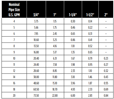
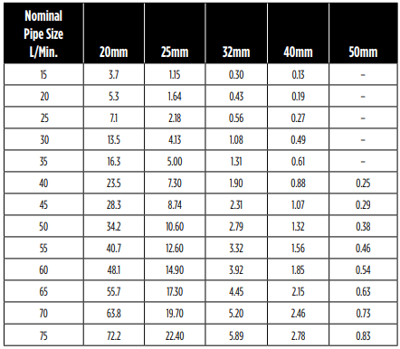
7. Add piping and coupling to join up the service line. The size of the service line required is governed entirely by the amount of water needed and the length of the pipe. The pipe selected should be large enough so that the friction loss (determined from Table 1, Friction Loss for Plastic Pipe) will never exceed 20 ft (6 m) of head.
8. Remove the PVC cap on the air valve on the tank.
9. Check the tank pre-charge with a tire gauge. It should be equal to 2 psi below the pressure switch cut-in setting (the pressure at which the pump will start). For this pump that is 30 psi, therefore the pre-charge pressure should be adjusted to 28 psi. Use a tire pump or air compressor to charge the tank, if necessary.
10. Replace and tighten the PVC cap on the air valve.
11. See Typical Installations for examples of different pump/tank configurations.
12. Verify everything has been completed using the Installation Checklist provided in this manual.
Table 1 - FRICTION LOSS FOR PLASTIC PIPE*
Loss of head in feet due to friction per 100 feet of pipe.
Loss of head in meters, due to friction per 100 meters of pipe.
*For galvanized pipe, double the figures.
PRIMING THE PUMP
WARNING DO NOT RUN THE PUMP BEFORE PRIMING IT; THE SEAL AND IMPELLER COULD BE PERMANENTLY DAMAGED.
NOTE: You will need enough water to fill the suction line(s) and casing. Priming time depends on the distance from the water source to the pump (5-15 minutes).
USING AN INLINE CHECK VALVE
1. Open the discharge valve on service line and nearby tap to monitor water flow.
2. With a wrench, remove the priming plug.
3. Pour clean water through the priming plug opening.
4. Continue filling the pump until water flows out of the priming hole.
5. Reinstall the priming plug, hand tighten.
6. Start the pump. If a tap is visible, you may see a short discharge of water that will last 5-10 seconds.
7. Run the pump for 2 minutes and then shut it off. Remove the priming plug.
8. You have completed the first priming cycle, consisting of Steps 3 to 7. This process will have to be repeated from 2 to 6 times, depending on the length of your suction line. (Approximately one priming cycle for every 5 ft [1.5 m] of suction line.) You will know when to stop because the pump will begin to pump water continuously.
9. Once the pump begins pumping water continuously, firmly tighten the priming plug with a wrench.
10. If the pump does not draw water within 8 tries, shut it off and check the suction line for leaks.
USING A FOOT VALVE
1. Open the discharge valve on the service line and nearby tap to monitor water flow.
2. With a wrench, remove the priming plug.
3. Pour clean water through the priming plug opening. You will need approximately 1 quart (1 liter) of water for every 3 ft (1 m) of suction line. NOTE: If you are unable to fill the suction line, please follow the directions for an inline check valve.
4. Continue filling the pump until water flows out of the priming hole.
5. Reinstall the priming plug, hand tighten.
6. Start the pump. If the pump is primed correctly it should start pumping water immediately.
7. If within 2 minutes water is not being pumped continuously, stop the pump. Remove the priming plug. Repeat Steps 3 through 7. If this does not work, stop the pump and check the suction line for leaks.
8. Once the pump begins pumping water continuously, firmly tighten the priming plug with a wrench.
MAINTENANCE
WARNING RISK OF ELECTRICAL SHOCK
Before servicing motor-operated equipment, shut off the power at the main electrical panel and disconnect the power supply from motor and accessories. Use safe working practices during servicing of equipment.
PERFORM INSPECTIONS MONTHLY
1. Ensure pump is still securely bolted to the foundation.
2. To avoid any fire hazards, ensure that there is adequate clearance from any combustible materials, shelving or cabinets. Ensure there are no leaves or debris near the pump.
3. Ensure that the motor is securely wired into a proper GFCIprotected circuit. Test the GFCI periodically by pressing the test switch when the pump is operating. This should shut off the pump. If the GFCI does not shut the pump off, have an electrician replace the GFCI as soon as possible. Remember to reset the GFCI by pressing the reset switch.
4. Look for any signs of leaks in pipes. Replace or repair, if necessary.
5. Clean the exterior of the pump, if needed, with a solution of vinegar and water.
DRAINING
Should the unit be subject to freezing, it will be necessary to drain the pump and tank. To do this, shut off the power to the pump at the main electrical panel. Open a tap in the water system to release the pressure. Remove the drain and priming plugs from the pump casing. Remove the pressure tank drain plug (if so equipped). Allow ample time for the system to drain before reinstalling the plugs.
LUBRICATION
The pump requires none.
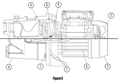
REPLACING MECHANICAL SEAL (See Figure 8)
CAUTION ONLY DULY QUALIFIED PERSONS SHOULD PERFORM MAINTENANCE ON ELECTRICAL AND/OR MECHANICAL DEVICES.
Disassembly:
1. Shut off the power to the pump at the main service panel and disconnect the power supply from motor.
2. Open a tap in the water system to release the pressure.
3. Remove the drain and fill plugs to allow the pump to drain.
4. Remove the bolts (1) and remove casing (2).
5. Remove fan shroud fasteners from the motor and remove the fan shroud (3).
CAUTION Care must be taken not to damage the motor fan or shroud.
6. Remove the impeller (4) by firmly holding on to the motor fan (5) and turn the impeller in a clockwise direction.
7. Slip rotating seal (9) off the shaft.
8. Remove motor tie bolts and remove motor (6) from adapter (7) by slightly tapping end of motor shaft with a mallet.
9. Remove the adapter plate and the O-ring.
Reassembly:
1. Clean all parts thoroughly before assembling.
2. Lightly lubricate (soapy water) the rubber cap on the ceramic seal (8) and push it into the adapter (7) using thumbs only. Make sure the smooth surface of the ceramic seat faces outward.
CAUTION Do not use petroleum-based cleaners or lubricants.
CAUTION Care must be taken not to contaminate the ceramic seal face.
NOTE: If the pump will remain out of service for longer than one week, the seal components must be installed dry (no lubrication).
3. Reassemble the motor (6) to the adapter. Align the tabs of the adapter plate with the slot at the bottom of the motor housing.
4. Lubricate the rubber components of the rotating seal (9) (soapy water) and slip it on to the shaft with the ‘carbon’ ring towards the ceramic seat.Replace the impeller (6) and the diffuser (4).
CAUTION Care must be taken not to contaminate the ceramic seal face.
5. Replace the impeller (4) and the shroud with fasteners. Lubricate and replace the O-ring.
6. Replace the casing (2), making sure that O-ring is not damaged and is in place.
7. Replace drain and fill plugs.
8. Reconnect power.
9. Prime the pump.
TROUBLESHOOTING
PROBLEM
POSSIBLE CAUSE
Motor will not start
No power to pressure switch due to blown fuses, open switches or loose connections.
Pump pressure switch not closed.
Pump fails to deliver water
Pump not completely primed.
Suction lift is too great.
Foot valve is either not submerged, buried in the mud or plugged.
Restrictor valve is fully closed.
Pump loses prime
Air leaks in suction line.
Well draws down too far.
Faulty foot valve.
For well point installations where pump is losing pressure or unable to prime
Have an electrician install a low pressure cut-off switch to shut down the pump prior to critical failure.
Install or adjust a restrictor valve to offset available capacity.
Add a larger tank (20 gallon or larger) for additional capacity.
Pump delivers water but not at rated capacity
Leaks in suction or discharge line.
Foot valve, suction line, impeller or nozzle are partially plugged.
Suction lift is greater than recommended.
Improper impeller rotation or low speed.
Venturi or diffuser is plugged.
Motor is wired for improper voltage.
Low line voltage at motor.
Filtration cartridge (if used) needs changing or is not installed properly.