Loading ...
Loading ...
Loading ...
EN-4
English
4.1
4.1 Installation of the Return
Sensor
Select the appropriate sensor for the corresponding regula-
tion (consider the enclosure).
The return sensor is inserted in the immersion sleeve of the
DDV.
For improved heat transfer the use of thermal compound is
recommended.
The return sensor is connected to terminal J2-B2 in control-
ler N1
The existing return sensor must be disabled.
The circulation pumps are not supplied and must be se-
lected in accordance with pressure loss and flow volume of
the system. All commercial circulation pumps with nominal
diameter of DN 25 (DDV 25) and DN 32 (DDV 32) are appli-
cable.
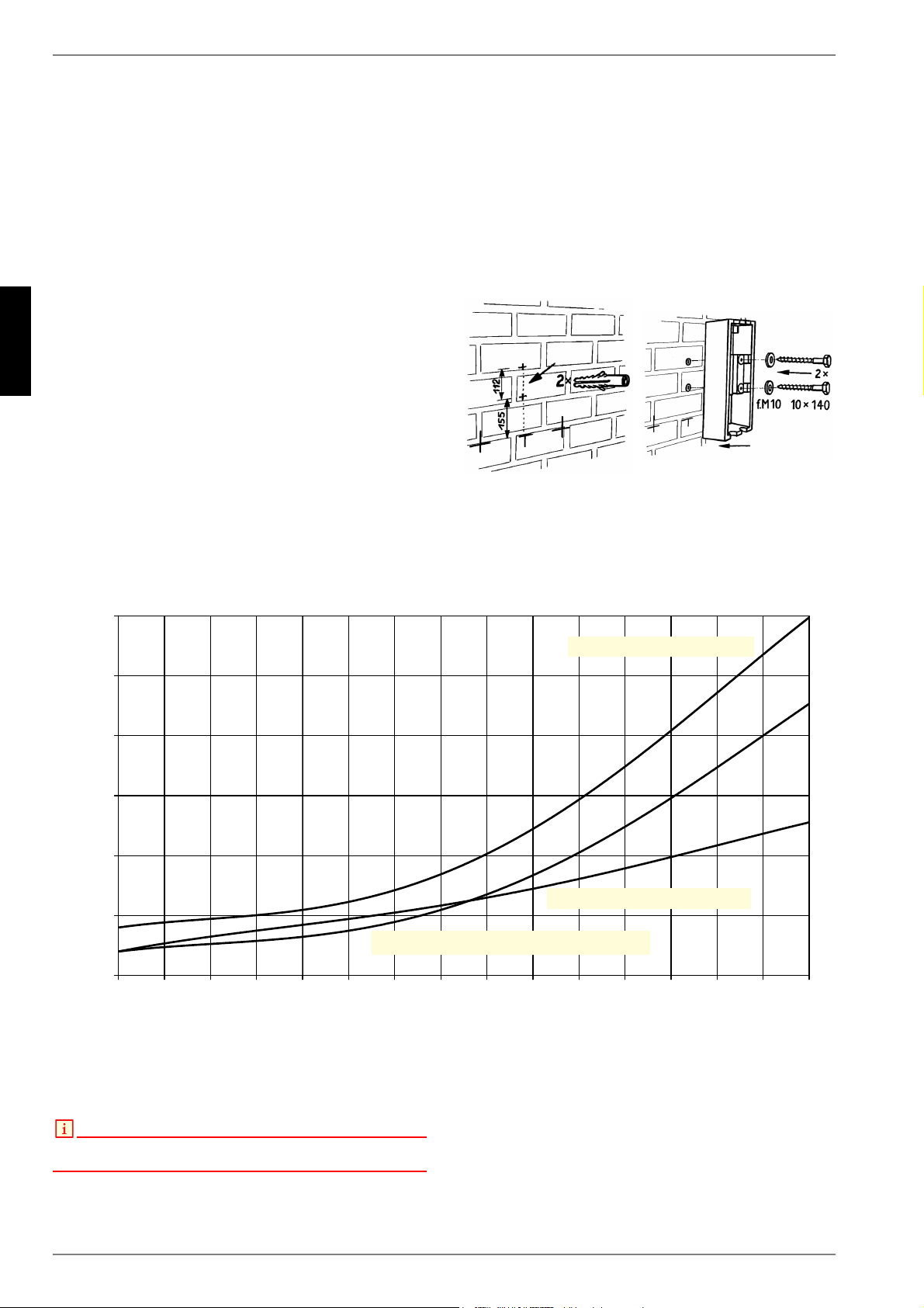
4.2 Wall mounting
DDV with insulation attached to existing pipework.
Tighten fitting hand-tight.
Align dual differential pressureless manifold and mark out
the drilling holes. Then remove dual differential pressureless
manifold with insulation again.
Drill holes according to marks and insert dowels.
Affix bottom tray of insulation with screws (supplied) to the
wall.
Install DDV and connect wtih the pipeline network.
5 Volume Flow - Pressure Loss Diagram
The DDV 25 is recommended for heat pumps for heating pur-
poses up to a maximum heating water flow of 2 m³/h.
The DDV 32 is recommended for heat pumps for heating pur-
poses up to a maximum heating water flow of 2.5 m³/h.
NOTE
With heating and cooling systems the project engineering documents are
to be observed !
9ROXPH)ORZ3UHVVXUH/RVV'LDJUDPIRU''9DQG''9
9ROXPHIORZ>OK@
3UHVVXUHORVV>EDU@
)ORZFRXUVH+HDWSXPSEXIIHUWDQNFRQVXPHU
)ORZFRXUVH%XIIHUWDQNFRQVXPHU
)ORZFRXUVH+HDWSXPSEXIIHUWDQN
Loading ...
Loading ...
Loading ...