
Loading ...
Loading ...
Loading ...
7
Pre-Installation
5.8 Building Regulation G3 Discharge
Requirements
As part of the requirements of Building Regulation G3
complies with BS EN 1490. Any discharge from a water
heater system should be conveyed to where it is visible,
but will not cause danger to persons in or about the
building. The tundish and the discharge pipes should be
Building Regulation approved document G3, (England
and Wales), Part P of Northern Ireland and Standard
4.9 of Scotland.
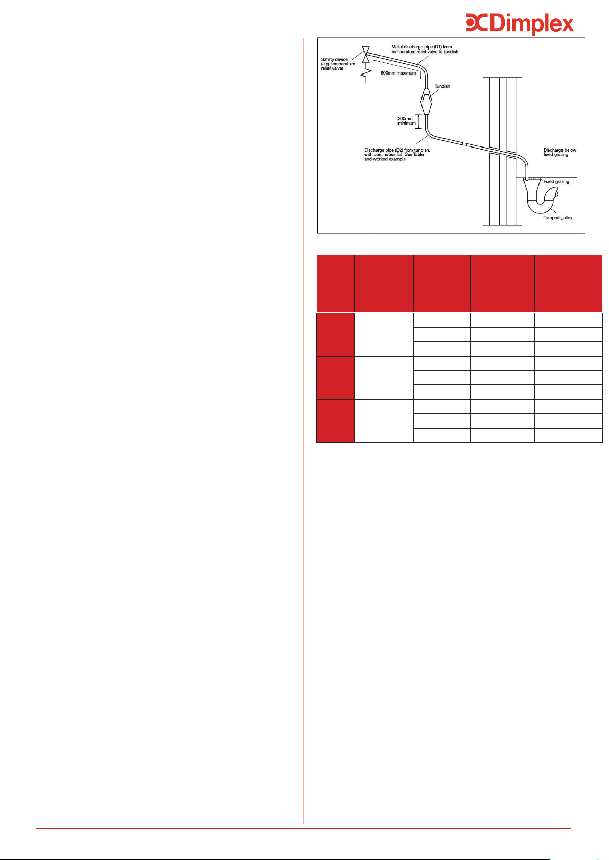
The discharge pipe (D2) from the Tundish should:
- “have a vertical section of pipe at least 300mm long
below the tundish before any elbows or bends in the
pipework and be installed with a continuous fall of at
The discharge pipe (D2) should be made of:
- “metal; or other material that has been demonstrated
to be capable of safely withstanding temperatures of
the water discharged and is clearly and permanently
marked to identify the product and performance
standard”
Dimplex strongly recommends the use of metal
pipework only and Dimplex does not take responsibility
for any damage caused from discharges.
The discharge pipe D2 should be at least one pipe size
larger than the nominal outlet size of the safety device
unless its total equivalent hydraulic resistance exceeds
that of a straight pipe 9m long, i.e. for discharge pipes
between 9m and 18m the equivalent resistance length
should be at least two sizes larger than the nominal
outlet size of the safety device; between 18m and 27m
at least 3 sizes larger, and so on; bends must be taken
Figure 2, Table 2 and the worked example.
Note: An alternative approach for sizing discharge
pipes would be to follow Annex D, section D.2 of BS
6700:2006 + A1:2009).
This example is for a G½ temperature relief valve with
a discharge pipe (D2) having 4 No. 22mm elbows and
length of 7m from the tundish to the point of discharge.
From Table 2, the maximum resistance allowed for a
straight length of 22mm copper discharge pipe (D2)
from a G½ temperature relief valve is 9.0m. Subtract the
resistance for 4 No. 22mm elbows at 0.8m each = 3.2m.
Therefore the maximum permitted length equates to
5.8m, which is less than the actual length of 7m,
therefore calculate the next largest size.
Maximum resistance allowed for a straight length of
28mm copper discharge pipe (D2) from a G½
temperature relief valve is: 18m.
Subtract the resistance for 4 No. 28mm elbows at 1.0m
each = 4m.
Therefore the maximum permitted length equates to
14m.
As the actual length is 7m, a 28mm (D2) copper pipe will
be satisfactory.
- Where a single common discharge pipe serves more
than one system, it should be at least one pipe size
larger than the largest individual discharge pipe (D2)
to be connected.
Figure 2: Typical discharge pipe arrangement
If required, precautions can be taken to minimise
conditioner or water softener. These devices should be
installed in hard water areas where high water
storage temperatures are required, i.e. greater than
60°C storage temperatures, particularly when water
hardness exceeds 200ppm. Should the water heater
require de-scaling, this must be performed by a
Value
outlet
size
Minimum size
of discharge
pipe before
tundish (mm)
Minimum size
of discharge
pipe after
tundish (mm)
Maximum
allowed length
of pipe after
tundish (m)
Length to be
subtracted for
each elbow or
bend
(m)
G1/2 22 9
27
22 9
27
G1 9
27
Loading ...
Loading ...
Loading ...