Loading ...
Loading ...
Loading ...
109
17. Disassembly Instructions
Note: This part is for reference, the photos may have slight difference with your machine.
17.1 Indoor unit
Ducted Unit
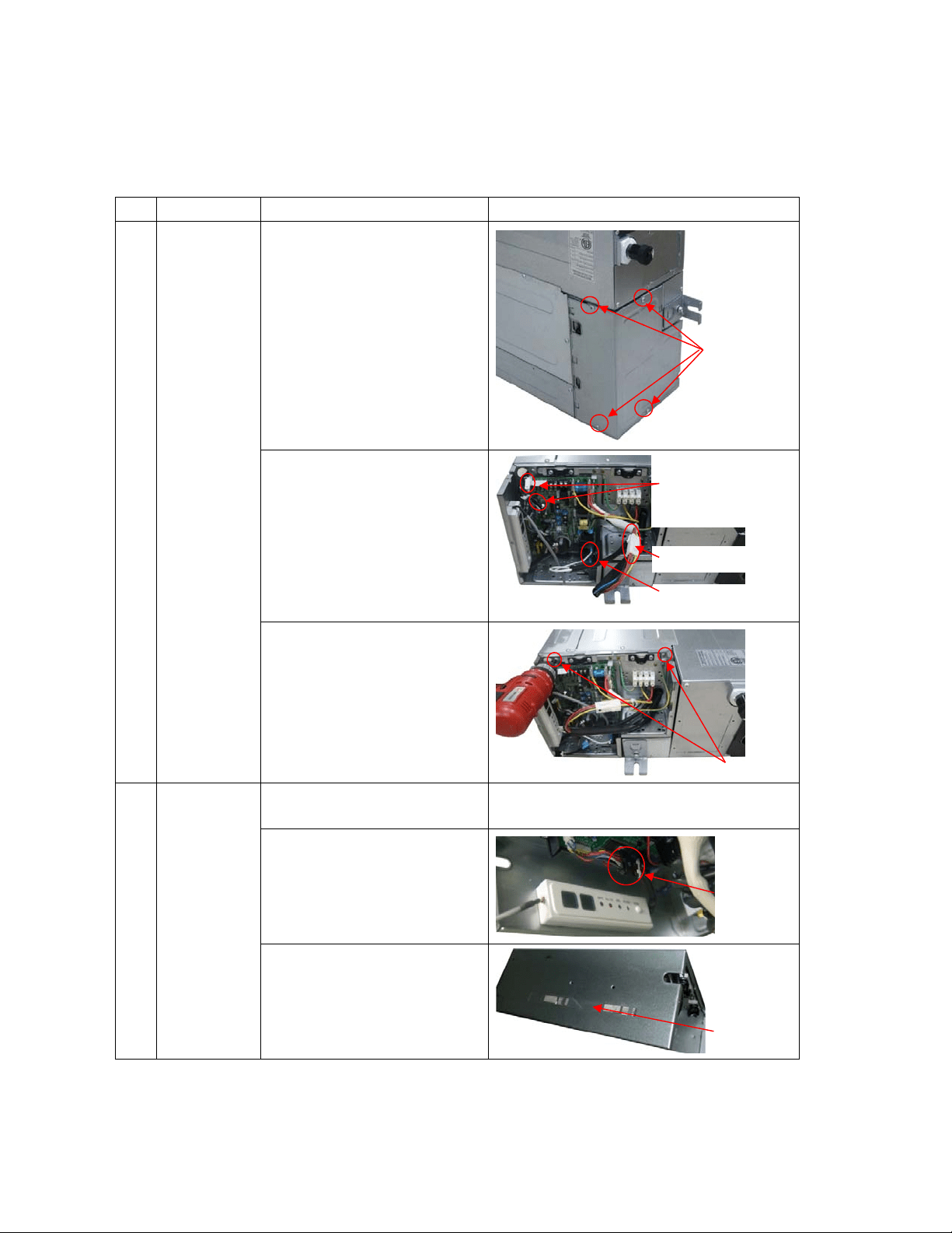
No. Parts name Procedures Remarks
1 Remove the
electronic
control box
1) Screw off the screws to
remove the cover of
electronic control
box
2) Disconnect the fan motor
wire, fan capacity wire,
room t
emperature sen
sor
w
ire and evaporator
temperature sensor wire
3) Screw off the screws to
remove elect
ronic
co
ntrol box
2 Remove the
display
board
1) Remove the cover o
f
e
lectronic control
box
Repeat the operation of step1 of No1
2) Disconnect the display
board wire connected to
PC
B
3) Remove the sticker
Four screws
Connector
Sticker
2 screws
Plug of room
temperate sensor
and evaporator
temperature sensor
Fan motor wire
Fan capacity wire
Loading ...
Loading ...
Loading ...