Loading ...
Loading ...
Loading ...
6
• Select a wall to the exterior of the building. This wall should have the required clearance to combustibles inside and out
as mentioned in this manual. Make certain that electrical wires, conduit, water or gas pipes do not pass through the area
you have selected.
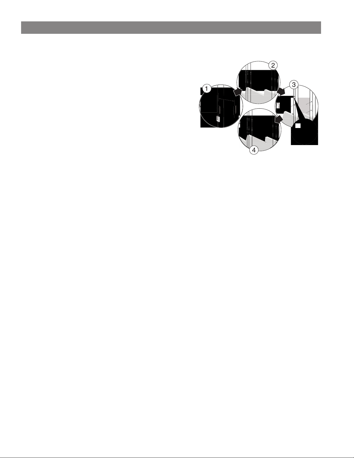
STEP: 1 MOUNT THE WALL PLATE
Note: Any material covering the wall (such as sheetrock) must not exceed 5/8” 16 mm).
Option 1: Mounting on a wood-stud wall
1. Locate the studs in exterior wall. Verify the center of the stud with an
edge-to-edge stud fi nder. Mark center point at predetermined height
which meets all clearance requirements of the appliance.
Note: Make sure that the opening for the exhaust thimble is
not to close to a stud in the wall before the hole is cut.
2. At the wall height that was determined in the previous step, place
a mid-sized nail through the center triangular shaped hole of the
mounting plate to hold it while the locations of the mounting holes
and the exhaust/intake through hole are marked. Make sure that the
wall mounting plate is fl ush against the wall, then level the mounting
plate and verify that pilot holes are centered properly on the studs. Use
a pencil to mark the pilot hole locations, and intake/ exhaust through
hole, then remove the mounting plate from the wall.
3. Drill the four pilot holes to a depth of 2” (75 mm) using a 5/32” (3.96 mm) diameter drill bit.
4. Find the center of the through hole for the wall thimble and drill a pilot hole all the way through the wall to the exterior with
an installer bit. Use this hole as a center point to cut your hole through the exterior wall.
5. Carefully cut exhaust/intake through hole in exterior wall completely through to the outside. (SEE VENT CLEARANCES
SECTION TO INSURE PROPER INSTALLATION)
6. Install the wall thimble included with the vent kit to the manufactures instructions.
7. Realign the wall mount with the pilot holes and exhaust/intake through hole. Insert the four 1/4” x 2” lag bolts with washers,
and tighten the lag bolts until the wall mounting bracket is pulled fi rmly against the exterior wall.
WARNING: AVOID POTENTIAL INJURIES OR PROPERTY DAMAGE! DO NOT OVER-TIGHTEN THE LAG BOLTS.
THIS COULD POTENTIALLY STRIP THE MOUNTING HOLES AND CAUSE THE BOLTS NOT TO HOLD CORRECTLY.
Option 2: Mounting on a solid concrete or concrete block wall
1. Level the wall plate and mark the hole locations.
2. At the wall height you determined in the previous step, place a small nail thru center triangle hole of bracket and align the
wall mount against the wall. Level bracket and verify that pilot holes are not located in the mortar of the cinder blocks. Use
a pencil to mark the pilot hole locations, and intake/exhaust thru hole then remove the wall plate.
3. Drill pilot holes to a depth of 2” (75 mm) using a 5/32” (3.96 mm) diameter masonry drill bit.
4. Carefully cut intake/exhaust thru hole in exterior wall thru to the outside. (SEE VENT CLEARANCES SECTION TO INSURE
PROPER INSTALLATION)
5. Insert 1/4” concrete wall anchors into the pilot holes and make sure that the anchors are seated fl ush with the concrete surface.
6. Align the wall plate with the anchors. Place washers over the screw holes in the wall plate, insert 1/4” x 2” lag bolts through
the washers, and then tighten the lag bolts until the washers are pulled fi rmly against the wall plate and the wall mount is
pulled fi rmly against the exterior wall.
STEP: 2 MOUNTING THE HEATING UNIT TO THE WALL PLATE
Note: The Heating Unit is heavy. You will need assistance with this step.
1. Before hanging the unit on the wall bracket the exhaust/intake transition piece needs to be mounted on the back of the unit.
On the exhaust side of the unit there is a ring that is held on with four screws, it needs to be removed so the transition piece
can be mounted. Use the supplied Phillips head self-tapping screws to attach the transition piece. Once the transition piece is
mounted the ring on the outside of the unit can be put back on.
2. After you have your hole cut and mounting bracket secured to the wall, the heating unit can hung on the bracket.
3. Align /intake with the hole in the wall mounting bracket and thimble, and carefully insert heating unit. Tilt the top of the
heating unit towards the wall and lower onto the wall mounting bracket making sure that the right and left bracket mounted
to the unit hooks over the top of the wall mounting bracket. Allow the Heating Unit to pivot downward becoming parallel to
the wall mounting bracket. Lift the unit up and the lower hooks will engage with the mounting bracket.
4. Once the unit is securely hanging on the wall mounting bracket there are two 7/16” head bolt on the bottom of the bracket
that need to be tightened down to lock the unit to the bracket.
5. Once the unit is locked down the exhaust/ intake pipe can be attached to the unit on the outside of the house.
5/8”
[16mm]
16”
[406mm]
3”
[75mm]
WALL INSTALLATION
Loading ...
Loading ...
Loading ...