IN079 Rev B 0118 13 Saber Way, Ward Hill, MA 01835 | homeaire.com
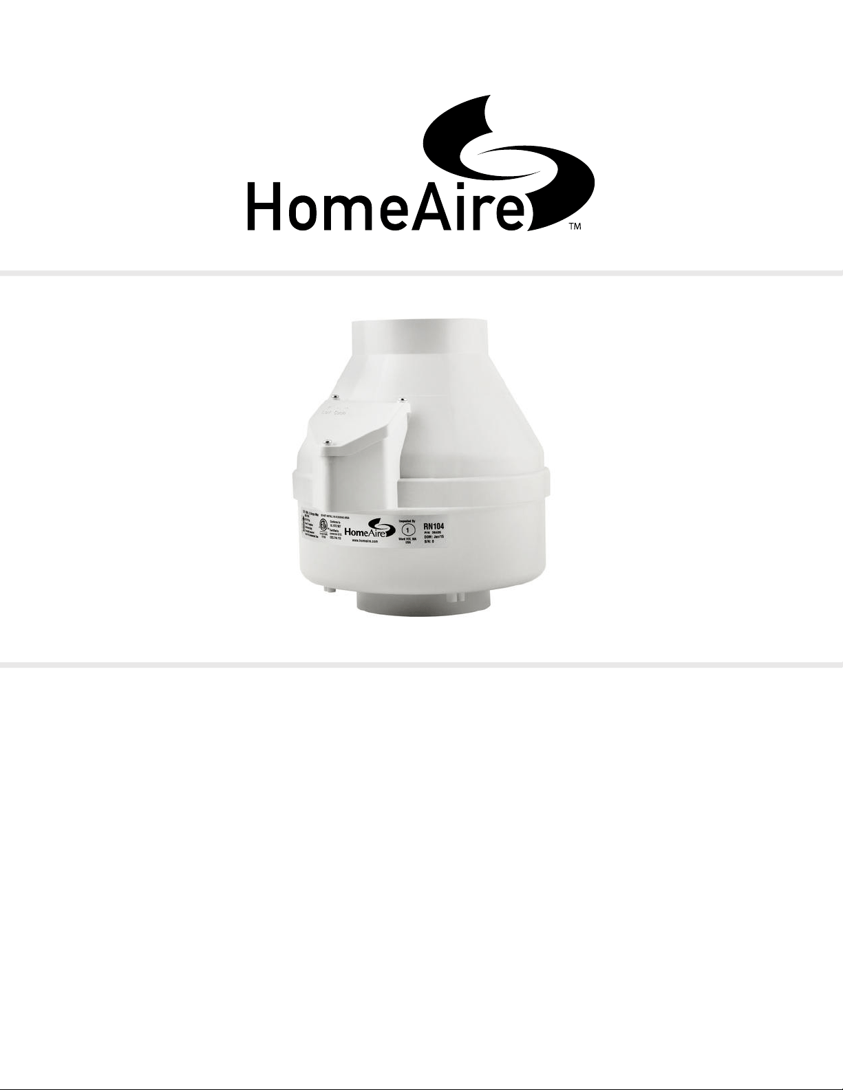
RN104
Installation Instructions

IN079 Rev B 0118 23 Saber Way Ward, Hill, MA 01835 | homeaire.com
Fan Installation & Operating Instructions
RN104
Please Read and Save These Instructions.
DO NOT CONNECT POWER SUPPLY UNTIL FAN IS COMPLETELY INSTALLED. MAKE SURE ELECTRICAL
SERVICE TO FAN IS LOCKED IN “OFF” POSITION. DISCONNECT POWER BEFORE SERVICING FAN.
1. WARNING! For General Ventilating Use Only. Do Not Use to Exhaust Hazardous, Corrosive or Explosive Materials,
Gases or Vapors.
2. NOTE: Fan is suitable for use with solid state speed controls; however, use of speed controls is not
generally recommended.
2. WARNING! Check voltage at the fan to insure it corresponds with nameplate.
3. WARNING! Normal operation of this device may affect the combustion airow needed for safe operation of fuel
burning equipment. Check for possible backdraft conditions on all combustion devices after installation.
4. NOTICE! There are no user serviceable parts located inside the fan unit.
Do NOT attempt to open. Return unit to the factory for service.
5. WARNING! Do not leave fan unit installed on system piping without electrical power for more than 48 hours. Fan
failure could result from this non-operational storage.
6. WARNING! TO REDUCE THE RISK OF FIRE, ELECTRIC SHOCK, OR INJURY TO PERSONS, OBSERVE THE
FOLLOWING:
a) Use this unit only in the manner intended by the manufacturer. If you have questions, contact the
manufacturer.
b) Before servicing or cleaning unit, switch power off at service panel and lock the service disconnecting
means to prevent power from being switched on accidentally. When the service disconnecting means
cannot be locked, securely fasten a prominent warning device, such as a tag, to the service panel.
c) Installation work and electrical wiring must be done by qualied person(s) in accordance with all applicable
codes and standards, including re rated construction.
d) Sufcient air is needed for proper combustion and exhausting of gases through the ue (chimney) of fuel
burning equipment to prevent backdrafting. Follow the heating equipment manufacturers’ guidelines
and safety standards such as those published by any National Fire Protection Association, and the
American Society for Heating, Refrigerating and Air Conditioning Engineers (ASHRAE), and the local code
authorities.
e) When cutting or drilling into a wall or ceiling, do not damage electrical wiring and other hidden utilities.
f) Ducted fans must always be vented to outdoors.
g) If this unit is to be installed over a tub or shower, it must be marked as appropriate for the application and
be connected to a GFCI (Ground Fault Circuit Interrupter) protected branch circuit.
IN079 Rev B 0118 33 Saber Way, Ward Hill, MA 01835 | homeaire.com
1.0 SYSTEM DESIGN CONSIDERATIONS
1.1 INTRODUCTION
The RN104 radon fan is intended for use by trained, professional, certied/licensed radon mitigators. The purpose of
these instructions is to provide additional guidance for the most effective use of RN104. These instructions should be
considered supplemental to EPA/radon industry standard practices, state and local building codes and regulations. In
the event of a conict, those codes, practices and regulations take precedence over these instructions.
1.2 FAN SEALING
The RN104 radon fan is factory sealed; no additional caulk or other materials are required to inhibit air leakage.
1.3 ENVIRONMENTALS
The RN104 radon fan is designed to perform year-round in all but the harshest climates without additional concern
for temperature or weather. For installations in an area of severe cold weather, please contact RadonAway for
assistance. When not in operation, the fan should be stored in an area where the temperature is never less than 32
degrees F or more than 100 degrees F.
1.4 ACOUSTICS
The RN104 radon fan, when installed properly, operates with little or no noticeable noise to the building occupants.
The velocity of the outgoing air should be considered in the overall system design. In some cases the “rushing” sound
of the outlet air may be disturbing. In these instances, the use of a RadonAway Exhaust Mufer is recommended.
(To ensure quiet operation of inline and remote fans, each fan shall be installed using sound attenuation techniques appropriate for the
installation. For bathroom and general ventilation applications, at least 8 feet of insulated exible duct shall be installed between the exhaust or
supply grille(s) and the fan(s). The RN104 is not suitable for kitchen range hood remote ventilation applications.)
1.5 GROUND WATER
In the event that a temporary high water table results in water at or above slab level, water may be drawn into the
riser pipes, thus blocking air ow to the RN104. The lack of cooling air may result in the fan cycling on and off as
the internal temperature rises above the thermal cutoff. Should this condition arise, it is recommended that the fan be
turned off until the water recedes, allowing for return to normal operation.
1.6 SLAB COVERAGE
The RN104 can provide coverage up to 2000+ sq. ft. per slab penetration. This will primarily depend on the sub-
slab material in any particular installation. In general, the tighter the material, the smaller the area covered per
penetration. Additional suction points can be added as required. It is recommended that a small pit (5 to 10 gallons
in size) be created below the slab at each suction hole.
Fan Installation & Operating Instructions
RN104 | P/N 23060
IN079 Rev B 0118 43 Saber Way Ward, Hill, MA 01835 | homeaire.com
1.7 CONDENSATION & DRAINAGE
Condensation is formed in the piping of a mitigation system when the air in the piping is chilled below its dew point.
This can occur at points where the system piping goes through unheated space such as an attic, garage or outside.
The system design must provide a means for water to drain back to a slab hole to remove the condensation. The
RN104 MUST be mounted vertically plumb and level, with the outlet pointing up for proper drainage through the fan.
Avoid mounting the fan in any orientation that will allow water to accumulate inside the fan housing. The RN104 are
NOT suitable for underground burial.
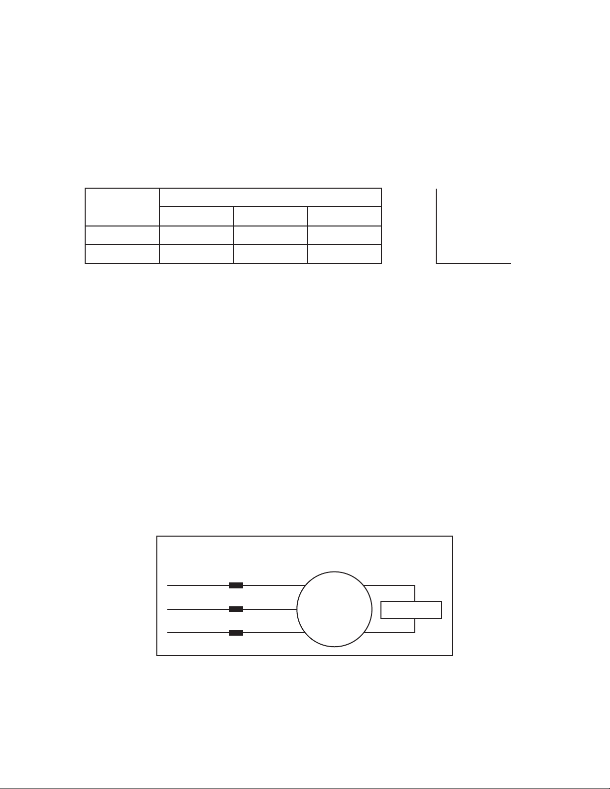
For RN104 piping, the following table provides the minimum recommended pipe diameter and pitch under several
system conditions.
*Typical RN104 operational ow rate is 25 - 90 CFM. (For more precision, determine ow rate by measuring Static Pressure, in
WC, and correlate pressure to ow in the performance chart in the addendum.)
Pipe
Diameter
Minimum Rise per Ft of Run*
@25 CFM @50 CFM @100 CFM
4” 1/8” 1/4” 3/8”
3” 1/4” 3/8” 1 1/2”
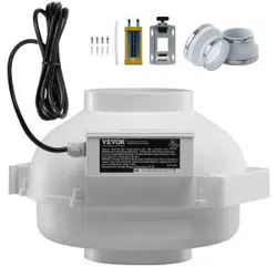
1.8 SYSTEM MONITOR & LABEL
A System Monitor, the manometer included in the RN104 System Kit or an audible alarm such as the (P/N 28001-
2, 28001-4 or 28421), is required to notify the occupants of a fan system malfunction. A System Label (provided
with RN104 System Kit sold by RadonAway) with instructions for contacting the installing contractor for service and
identifying the necessity for regular radon tests to be conducted by the building occupants must be conspicuously
placed in a location where the occupants frequent and can see the label.
1.8 ELECTRICAL WIRING
The RN104 operates on standard 120V, 60Hz AC. All wiring must be performed in accordance with National Fire
Protection (NFPA) National Electrical Code, Standard #70, current edition, for all commercial and industrial work,
and state and local building codes. All wiring must be performed by a qualied and licensed electrician. Outdoor
installations require the use of a UL Listed watertight conduit. Ensure that all exterior electrical boxes are outdoor
rated and properly sealed to prevent water penetration into the box. A means, such as a weep hole, is recommended
to drain the box.
1.9 SPEED CONTROLS
The RN104 Fan is rated for use with electronic speed controls; however, speed controls are generally not
recommended. If used, the recommended speed control is Pass & Seymour Solid State Speed Control (Cat. No.
94601-1).
RUN
RISE
120 VAC
Common
Ground
Capacitor
White
Black Brn
Brn/Wht
Green
Motor
GP/GPc XP/XPc XR Series Fan Wiring Diagram
RN104 Fan Wiring Diagram
IN079 Rev B 0118 53 Saber Way, Ward Hill, MA 01835 | homeaire.com
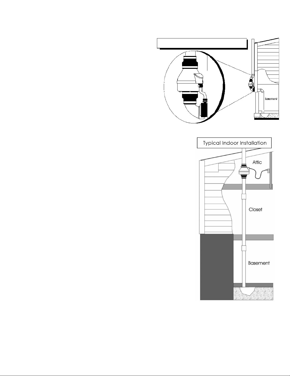
2.0 INSTALLATION
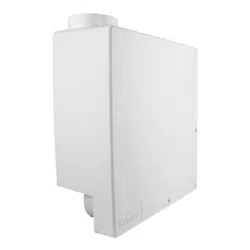
The RN104 can be mounted indoors or outdoors. (It
is suggested that EPA and radon mitigation standards
recommendations be followed in choosing the fan location.)
The RN104 Fan may be mounted directly on the system piping
or fastened to a supporting structure by means of an optional
mounting bracket.
The ducting from the fan to the outside of the building has a
strong effect on noise and fan energy use. Use the shortest,
straightest duct routing possible for best performance, and
avoid installing the fan with smaller ducts than recommended.
Insulation around the ducts can reduce energy loss and inhibit
mold growth. Fans installed with existing ducts may not
achieve their rated airow.
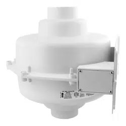
2.1 MOUNTING
Mount the RN104 vertically with outlet up. Insure the unit is plumb and level.
When mounting directly on the system piping assure that the fan does not
contact any building surface to avoid vibration noise.
2.2 MOUNTING BRACKET (optional)
The RN104 Fan may be optionally secured with a mounting bracket
manufactured by RadonAway (P/N 25007). Foam or rubber grommets may also
be used between the bracket and mounting surface for vibration isolation.
2.3 SYSTEM PIPING
Complete piping run, using exible couplings as a means of disconnect for
servicing the unit and for vibration isolation. As the fan is typically outside of
the building thermal boundary and is venting to the outside, installation of
insulation around the fan is not required.
2.4 ELECTRICAL CONNECTION
Connect wiring with wire nuts provided, observing proper connections (See
Section 1.8).
Note that the fan is not intended for connection to rigid metal conduit.
2.5 VENT MUFFLER (optional)
Install the mufer assembly in the selected location in the outlet ducting.
Solvent weld all connections.
The mufer is normally installed at the end of the vent pipe.
Typical RN104 Outdoor Installation
IN079 Rev B 0118 63 Saber Way Ward, Hill, MA 01835 | homeaire.com
2.6 OPERATION CHECKS & ANNUAL SYSTEM MAINTENANCE
______ Verify all connections are tight and leak-free.
______ Ensure the RN104 fan and all ducting are secure and vibration-free.
______ Verify system vacuum pressure with manometer. Insure vacuum pressure is within normal
operating range and less than the maximum recommended operating pressure.
(Based on sea-level operation, at higher altitudes reduce by about 4% per 1000 feet)
(Further reduce Maximum Operating Pressure by 10% for High Temperature environments.)
See Product Specications. If this is exceeded, increase the number of suction points.
______ Verify Radon levels by testing to EPA Protocol and applicable testing standards.
Typical CFM Vs. Static Pressure “WC
0” .5” 1.0” 1.5” 1.75” 2.0”
RN104 112 95 70 40 - -
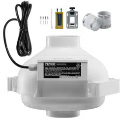
Model Size Weight Inlet/Outlet
RN104 9.5”H x 8.5” Dia. 6 lbs 4.5” OD
Model
Power Consumption
120VAC, 60Hz, 1.5 Amp Maximum
Maximum Recommended Operation Pressure*
(Sea Level Operation)**
RN104 45 - 66 watts 1.7” WC
RN104 Inlet/Outlet: 4.5” OD (4.0” PVC Sched 40 size compatible)
Size: 9.5H” x 8.5” Dia.
Weight: 6 lbs.
Recommended Ducting: 3” or 4” Schedule 20/40 PVC Pipe
PVC Pipe Mounting: Fan may be mounted on the duct
pipe or with integral anges.
Storage Temperature Range: 32-100 degrees F
Thermal Cutout: RN104: 120ºC (266ºF)
*Reduce by 10% for High Temperature Operation **Reduce by 4% per 1000 ft. of altitude.
The following chart shows fan preformance for the RN104 Fan:
RN104 Product Specications
Continuous Duty
Thermally Protected
Class B Insulation
3000 RPM
Residential Use Only
Rated for Indoor or Outdoor Use
IN079 Rev B 0118 73 Saber Way, Ward Hill, MA 01835 | homeaire.com
IMPORTANT INSTRUCTIONS TO INSTALLER
Inspect the HomeAire™ RN Series Fan for shipping damage within 15 days of receipt. Notify HomeAire of any
damages immediately. HomeAire is not responsible for damages incurred during shipping. However, for your benet,
HomeAire does insure shipments.
There are no user serviceable parts inside the fan. Do not attempt to open the housing. Return unit to factory for
service.
Install the RN104 Fan in accordance with all ANSI/AARST standard practices, state and local building codes, and
state regulations.
Provide a copy of this instruction or comparable radon system and testing information to the building occupants
after completing system installation.
Warranty
Subject to any applicable consumer protection legislation, HomeAire warrants that the RN104 Fan (the “Fan”) will be free from defects
in materials and workmanship for a period of two (2) years from the date of purchase (proof of purchase required).
HomeAire will replace any Fan which fails due to defects in materials or workmanship. The Fan must be returned (at Owner ’s cost)
to the HomeAire factory. Any Fan returned to the factory will be discarded unless the Owner provides specic instructions along with
the Fan when it is returned regardless of whether or not the Fan is actually replaced under this warranty. Proof of purchase must be
supplied upon request for service under this Warranty.
This Warranty is contingent on installation of the Fan in accordance with the instructions provided. This Warranty does not apply where
any repairs or alterations have been made or attempted by others, or if the unit has been abused or misused. Warranty does not cover
damage in shipment unless the damage is due to the negligence of HomeAire.
HomeAire is not responsible for installation, removal or delivery costs associated with this Warranty.
LIMITATION OF WARRANTY
EXCEPT AS STATED ABOVE, THE RN SERIES FAN IS PROVIDED WITHOUT WARRANTY OF ANY KIND, EITHER EXPRESS
OR IMPLIED, INCLUDING, WITHOUT LIMITATION, IMPLIED WARRANTIES OF MERCHANTABILITY AND FITNESS FOR A
PARTICULAR PURPOSE.
IN NO EVENT SHALL HOMEAIRE BE LIABLE FOR ANY DIRECT, INDIRECT, SPECIAL, INCIDENTAL, OR CONSEQUENTIAL
DAMAGES ARISING OUT OF, OR RELATING TO, THE FAN OR THE PERFORMANCE THEREOF. HOMEAIRE’S AGGREGATE
LIABILITY HEREUNDER SHALL NOT IN ANY EVENT EXCEED THE AMOUNT OF THE PURCHASE PRICE OF SAID PRODUCT. THE
SOLE AND EXCLUSIVE REMEDY UNDER THIS WARRANTY SHALL BE THE REPAIR OR REPLACEMENT OF THE PRODUCT, TO
THE EXTENT THE SAME DOES NOT MEET WITH HOMEAIRE’S WARRANTY AS PROVIDED ABOVE.
For service under this Warranty, contact HomeAire for a Return Authorization (RMA) Number and shipping information. No returns can
be accepted without an RMA. If factory return is required, the customer assumes all shipping costs to and from factory.
HomeAire™
3 Saber Way
Ward Hill, MA 01835
TEL. (800) 767-7080
FAX (978) 521-3964
Record the following information for your records:
Serial Number: Purchase Date: