Loading ...
Loading ...
Loading ...
Installat
ion and User Instructions R01128
-8 09/15
Page
21
Installation
4.5 Limitations
- The solar collector array must be
specified correctly, to ensure it is
compatible with the model of
cylinder installed. This is to prevent
the cylinder overheating or the solar
array to be exposed to prolonged
stagnation periods.
- The heat exchangers in this range of
cylinders have been specifically
designed for solar applications.
Great care must be taken if using
these cylinders with other heat
sources, due to the heat exchange
capacity of the product.
- Solar cylinders must be installed with
a solar hydraulic pump station,
which incorporates non-return
valves.
- When the cylinder is installed with a
low cost pump station which
incorporates only one non-return
valve, then an additional non-return
valve is to be installed within the
closed loop to prevent gravity
circulation.
5 Installation
5.1 Cold Water Inlet with
Inlet Control Group
5.1.1 Correctly site the
cylinder
Install the cylinder in an appropriate
location, ensuring all of the
recommendations have been
considered (see chapter 4.2).
5.1.2 Install the inlet group
The inlet group regulates the pressure
of the incoming mains water supply to
the cylinder and removes any debris
that might be water borne.
Note: Between the inlet group and
the cold water inlet on the cylinder
NO isolating device may be fitted,
as by doing so important safety
devices could be isolated!
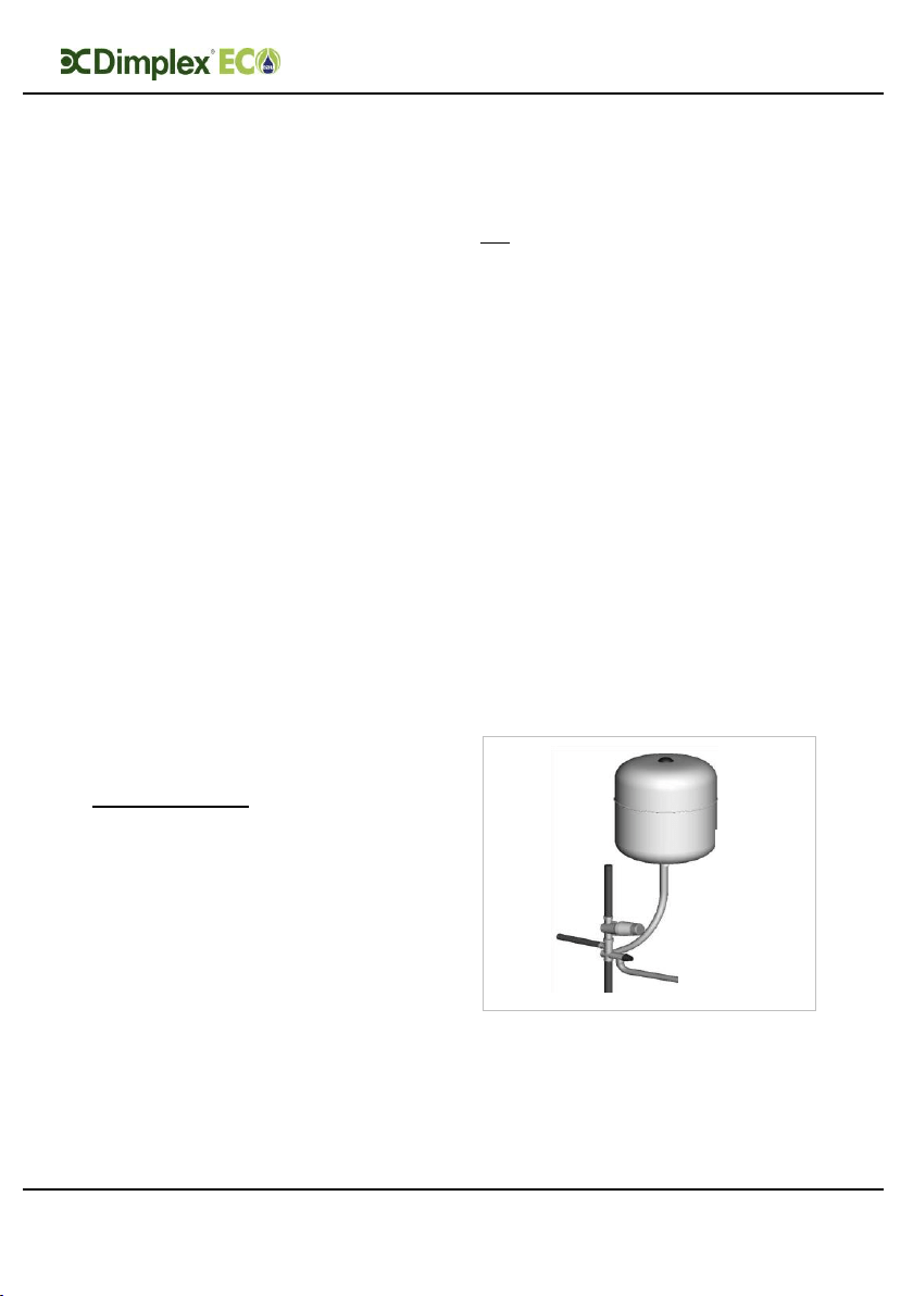
5.1.3 Expansion vessel
The expansion vessel is mandatory on
all EC-Eau cylinders and can be
connected directly to the cold water
inlet group, utilising the flexible hose
supplied with the vessel. The
expansion vessel should always be
fitted in accordance with the
manufacturer’s instructions. No
isolating device should be fitted
between the water cylinder and the
cold water inlet group.
Furthermore, it is recommended to
mount the vessel higher than the
cylinder to avoid having to drain the
cylinder when maintaining and
replacing the expansion vessel.
Figure 5: Connection of the expansion
vessel to the inlet group
Loading ...
Loading ...
Loading ...