Loading ...
Loading ...
Loading ...
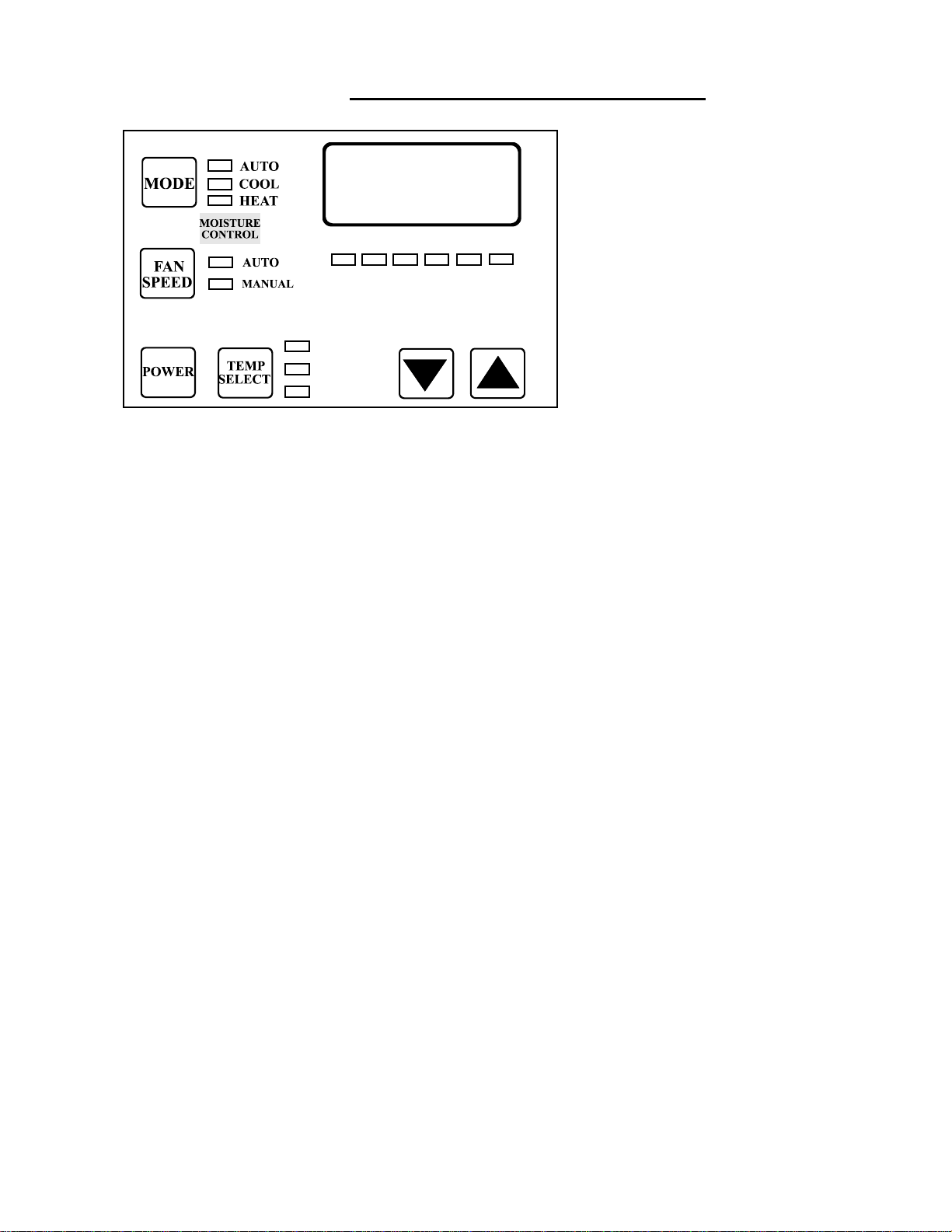
CHECKOUT OF UNIT OPERATION
POWER BUTTON: Press the power
button once to toggle the unit to the on
mode. Press the power button again to
toggle the unit to the off mode.
FAN BUTTON: Press and release the
fan button to advance from auto to
manual fan. Press and release to increase
the manual fan speeds, 1 through 6. Press
and release again returns to the auto fan
mode. The selected fan mode is indicated
by the Auto and Manual fan LED’s.
UP BUTTON: Momentarily press and
the set point will appear in the
temperature display. The set point increases one degree each time the up button is pressed and
released.
DOWN BUTTON: Momentarily press and release to display the set point. The set point is
decreased one degree each time the button is pressed and released.
MODE BUTTON: The Mode Button is used to select one of 2 Operating Modes. Press and release
to advance to the next mode. Continue to press and release until the desired Operating Mode is
reached. The mode selected is indicated by the Mode LED.
TEMP SELECT BUTTON: Press and release to view inside (return) air temperature, outside
(discharge) air temperature or set point. The appropriate LED will be lit indicating which
temperature is displayed.
THREE DIGIT DISPLAY: The inside (return) temperature is displayed whenever the control is
turned on. The display also provides a readout of the outside (discharge) air temperature which is
located in the supply airflow.
COOL MODE LED: The Cool Mode LED is lit when Cooling is selected.
MOISTURE CONTROL LED: The Moisture LED is lit when the Moisture Control is selected.
MANUAL FAN LED: The Manual Fan LED is lit when a manual fan speed is selected.
AUTO FAN LED: The Auto Fan LED is lit when automatic fan speed operation is selected.
FAN SPEED BAR GRAPH: There are six(6) individual fan speed LED’s. Each LED represents
one (1) fan speed. Low fan (1) is indicated by illuminating the first LED. High fan speed is
indicated by illuminating all six (6) LED’s.
LED: The system operating status (Compressor On or Off) is indicated by turning On the right most
decimal point in the 3 Digit Display.
INSIDE
OUTSIDE
SETPOINT
14
Loading ...
Loading ...
Loading ...