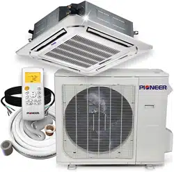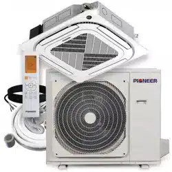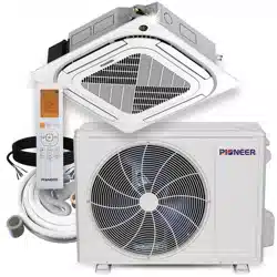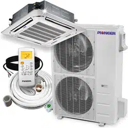
CASSETTE- TYP E AIR CONDI TION ER
Installation Manual
Super-Slim Ceiling Cassette
IMPORTANT NOTE:
Read this manual carefully before
installing or operating your new air
conditioning unit. Make sure to save
this manual for future reference.
Ceiling Cassette Type Ductless Split Systems
CB024 - CB036 - CB048 Compact Indoor Units
CYB024 - CYB036 - CYB048 System Sets
Accessories .................................................... 04
a. Indoor Unit Parts ......................................... 07
b. Indoor Unit Installation Instructions ....... 08
Safety Precautions ..................................... 05
Outdoor Unit Installation ......................... 11
a. Outdoor Unit Installation Instructions ...... 11
b. Outdoor Unit Types and Specifications .... 12
c. Notes on Drilling Hole in Wall .................... 13
Drainpipe Installation ............................... 14
Table of Contents
Installation Manual
Indoor Unit Installation
........................... 07
Installation Overview ............................... 06
1
2
5
3
4
6
Page 3
Refrigerant Piping Connection ....................... 16
A. Notes on Pipe Length and Elevation .............. 16
B. Refrigerant Piping Connection Instructions ...17
Wiring ................................................. 19
a. Outdoor Unit Wiring ................... 19
b. Indoor Unit Wiring ...................... 20
c. Power Specifications ................... 21
d. Wiring Diagram ........................... 22
Air Evacuation
................................................. 23
a. Evacuation Instructions ................................ 23
b. Note on Adding Refrigerant ....................... 24
Panel Installation .......................... 25
Test Run ............................................. 27
MC MC
7
8
9
10
11
LN
Page 4
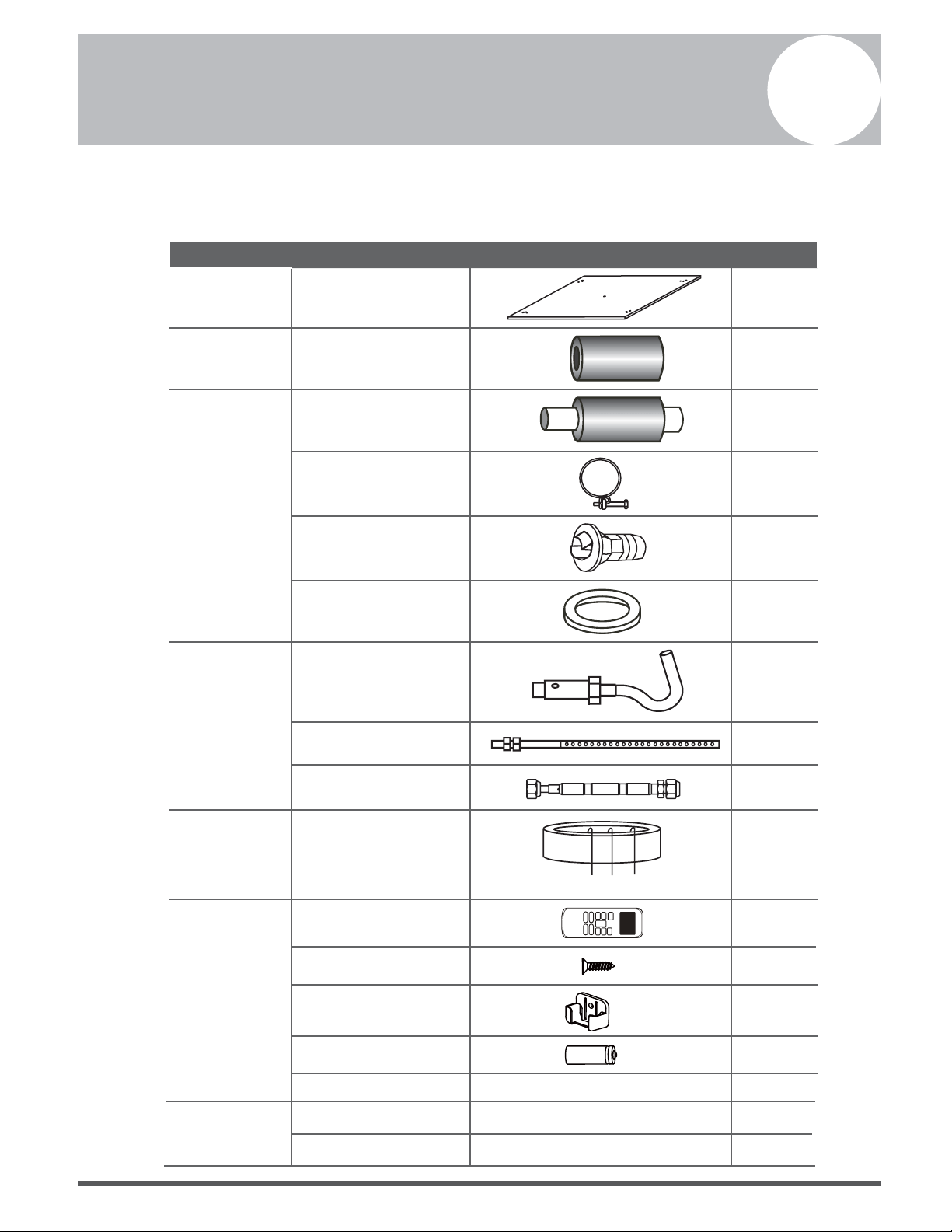
Accessories
1
The air conditioning system comes with the following accessories. Use all of the installation parts
and accessories to install the air conditioner. Improper installation may result in water leakage,
electrical shock and fire, or cause the equipment to fail.
Name Shape Quantity
Indoor unit
installation
Installation paper template
(some models)
1
Refrigeration
Fittings
Soundproof/insulation
sheath (some models)
1
Drainpipe
Fittings
Outlet pipe sheath (some
models)
1
Outlet pipe clasp (some
models)
1
Drain joint (some models)
1
Seal ring (some models)
1
Installation
Accessory (some
models)
Ceiling hook
4
Suspension bolt
4
Orifice tube (some units)
1
EMC Magnetic
Ring (some
models)
Remote
controller & Its
Frame (some
models)
Magnetic ring (wrap the
electric wires P & Q & E
around the magnetic ring
twice)
Q
P
E
1
1
2
1
1
1
1
2
Remote controller
Fixing screw for remote
controller holder ST2.9 x 10
Remote controller holder
Dry battery AAA
Owner’s manual
Installation manual
Remote controller illustration
Page 5
Safety Precautions
2
Read Safety Precautions Before Installation
Incorrect installation due to ignoring instructions can cause serious damage or injury.
The seriousness of potential damage or injuries is classified as either a WARNING or CAUTION.
WARNING
• Carefully read the Safety Precautions before installation.
•
In certain functional environments, such as kitchens, server rooms, etc., the use of specially
designed air-conditioning units is highly recommended.
• Only trained and certied technicians should install, repair and service this air
conditioning unit.
Improper installation may result in electrical shock, short circuit, leaks, fire or other damage to
the equipment and personal property.
• Strictly follow the installation instructions set forth in this manual.
Improper installation may result in electrical shock, short circuit, leaks, fire or other damage to
the equipment.
• Before you install the unit, consider strong winds, typhoons and earthquakes that might aect
your unit and locate it accordingly. Failure to do so could cause the equipment to fail.
• After installation, ensure there are no refrigerant leaks and that the unit is operating properly.
Refrigerant is both toxic and flammable and poses a serious health and safety risk.
Note about Fluorinated Gasses
1.
This air-conditioning unit contains fluorinated gasses. For specific information on the type of gas
and the amount, please refer to the relevant label on the unit itself.
2.
Installation, service, maintenance and repair of this unit must be performed by a certified
technician.
3.
Product uninstallation and recycling must be performed by a certified technician.
4.
If the system has a leak-detection system installed, it must be checked for leaks at least every 12
months.
5.
When the unit is checked for leaks, proper record-keeping of all checks is strongly recommended.
Failure to observe a warning may result in death. The appliance must be installed in
accordance with national regulations.
Failure to observe a caution may result in injury or equipment damage.
WARNING
CAUTION
Page 6
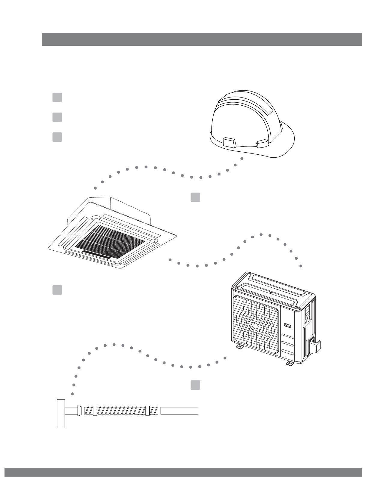
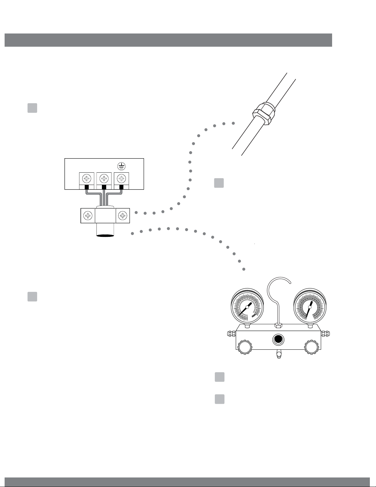
Installation Overview
3
stallation
e
rview
LN
1
2
3
4
5
MC MC
6
7
8
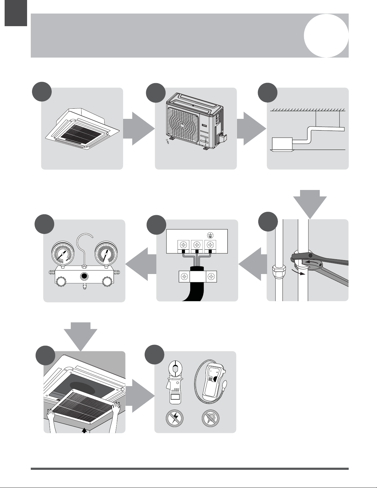
Install the indoor unit
(Page 7)
INSTALLATION ORDER
Install the outdoor unit
(Page 11)
Install the drainpipe
(Page 14)
Evacuate the refrigeration system
(Page 23)
Connect the wires
(Page 19)
Connect the refrigerant pipes
(Page 16)
Install the front panel
(Page 25)
Perform a test run
(Page 27)
Page 7
Indoor Unit Installation
4
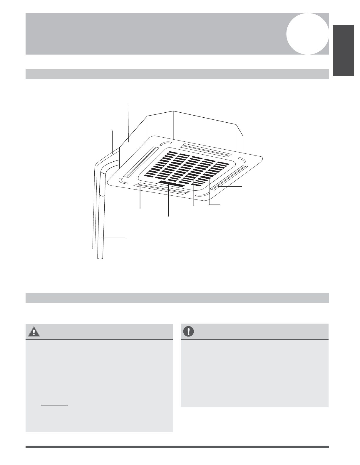
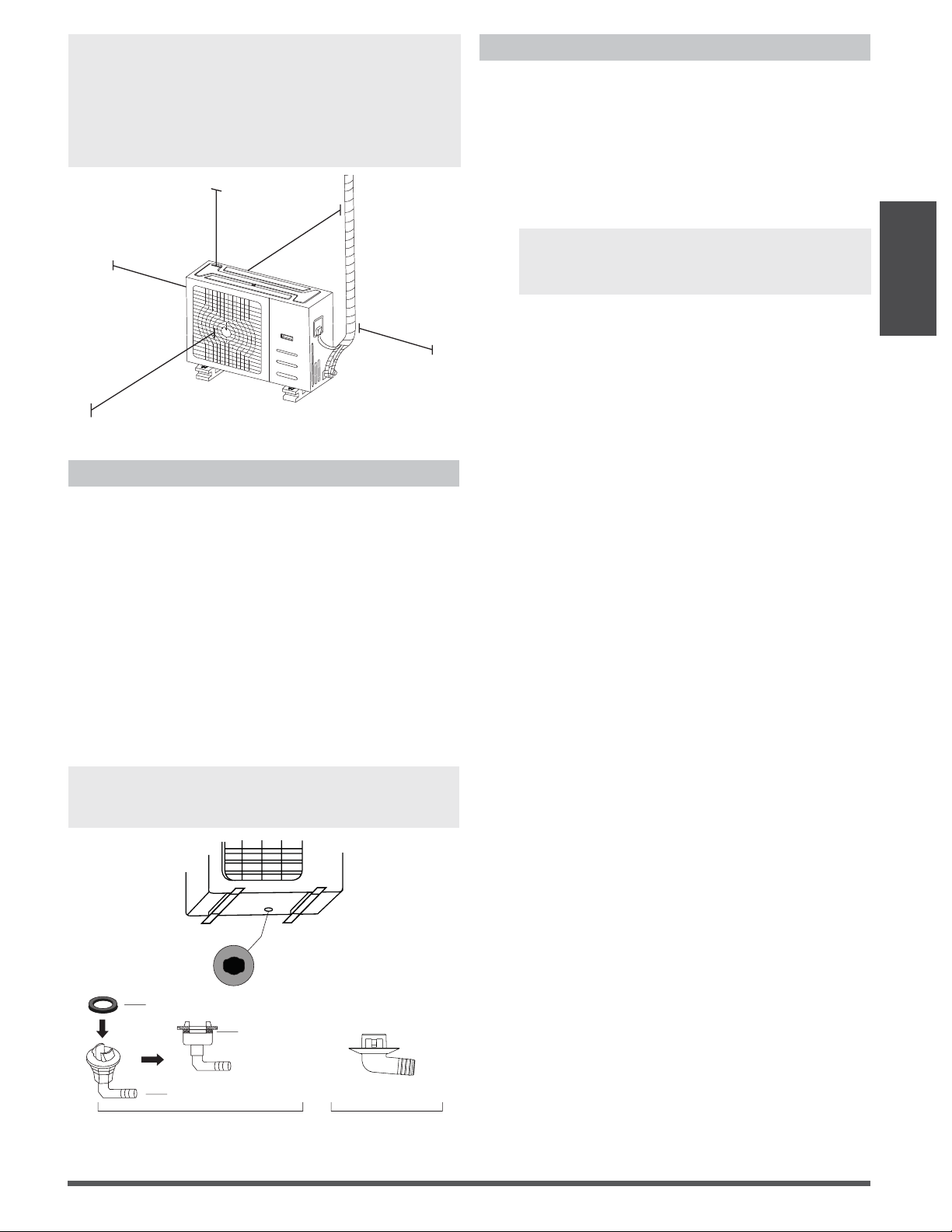
Indoor Unit Parts
Drain pump
(within indoor unit)
Drain pipe
Air outlet
Air inlet
Display panel
Front grille
Louver
Refrigerant pipe
Fig. 4.1
Safety Precautions
WARNING
• Securely install the indoor unit on a
structure that can sustain its weight. If the
structure is too weak the unit may fall
causing personal injury, unit and property
damage or death.
• Install the indoor unit at a height of more
than 2.5m (8’) above the floor.
• DO NOT install the indoor unit in the
bathroom or laundry room as excessive
moisture can short the unit and corrode the
wiring.
CAUTION
• Install the indoor and outdoor units, cables
and wires at least 1m (3.2’) from televisions
or radios to prevent static or image
distortion. Depending on the appliances, a
1m (3.2’) distance may not be sufficient.
• If the indoor unit is installed on a metal
part of the building, it must be electrically
grounded.
Indoor Unit
Installation
Page 8
Indoor Unit Installation Instructions
NOTE: Panel installation should be done after
piping and wiring.
Step 1: Select installation location
The indoor unit should be installed in a location
that meets the following requirements:
The unit is at least 1m (39”) from the nearest
wall.
There is enough room for installation and
maintenance.
There is enough room for the connecting
pipe and drainpipe.
The ceiling is horizontal and its structure
can sustain the weight of the indoor unit.
The air inlet and outlet are not impeded.
The airflow can fill the entire room.
There is no direct radiation from heaters.
CAUTION
DO NOT install the unit in the following
locations:
In areas with oil drilling or fracking
In coastal areas with high salt content in the air
In areas with caustic gases in the air, such
as near hot springs
In areas with power fluctuations, such as
factories
In enclosed spaces, such as cabinets
In kitchens that use natural gas
In areas with strong electromagnetic waves
In areas that store flammable materials or
gas
In rooms with high humidity, such as
bathrooms or laundry rooms
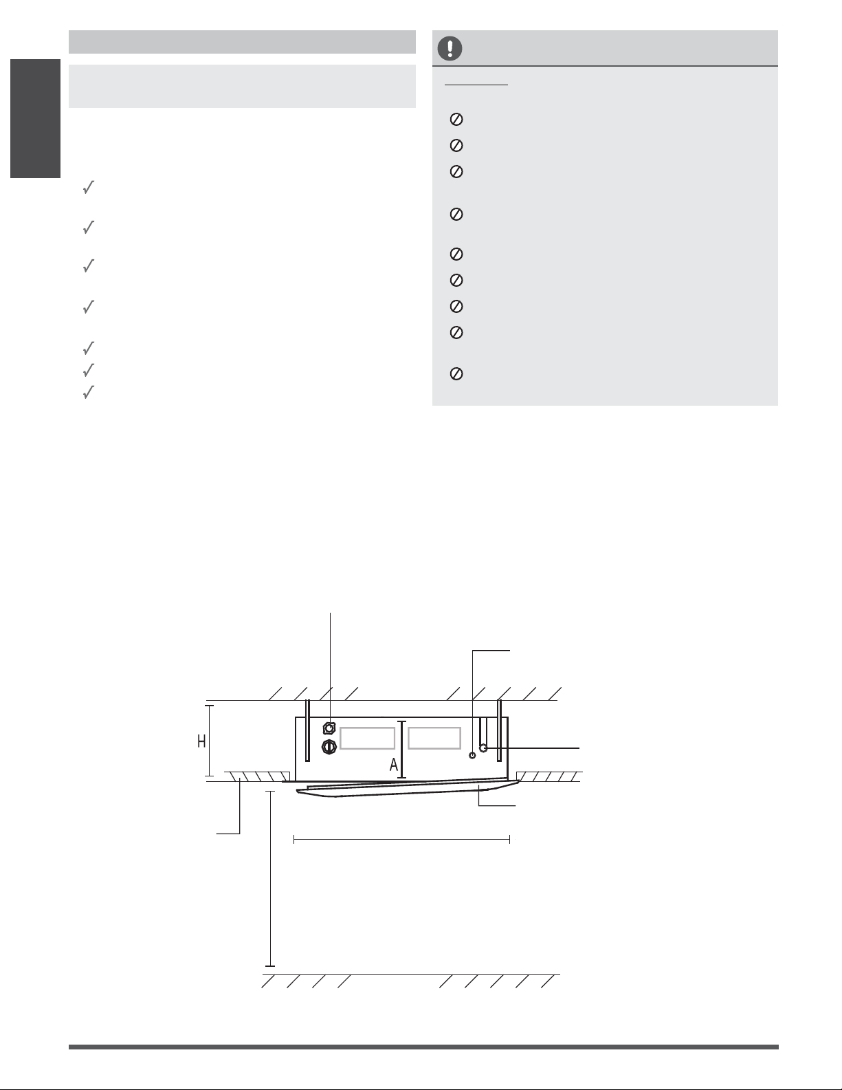
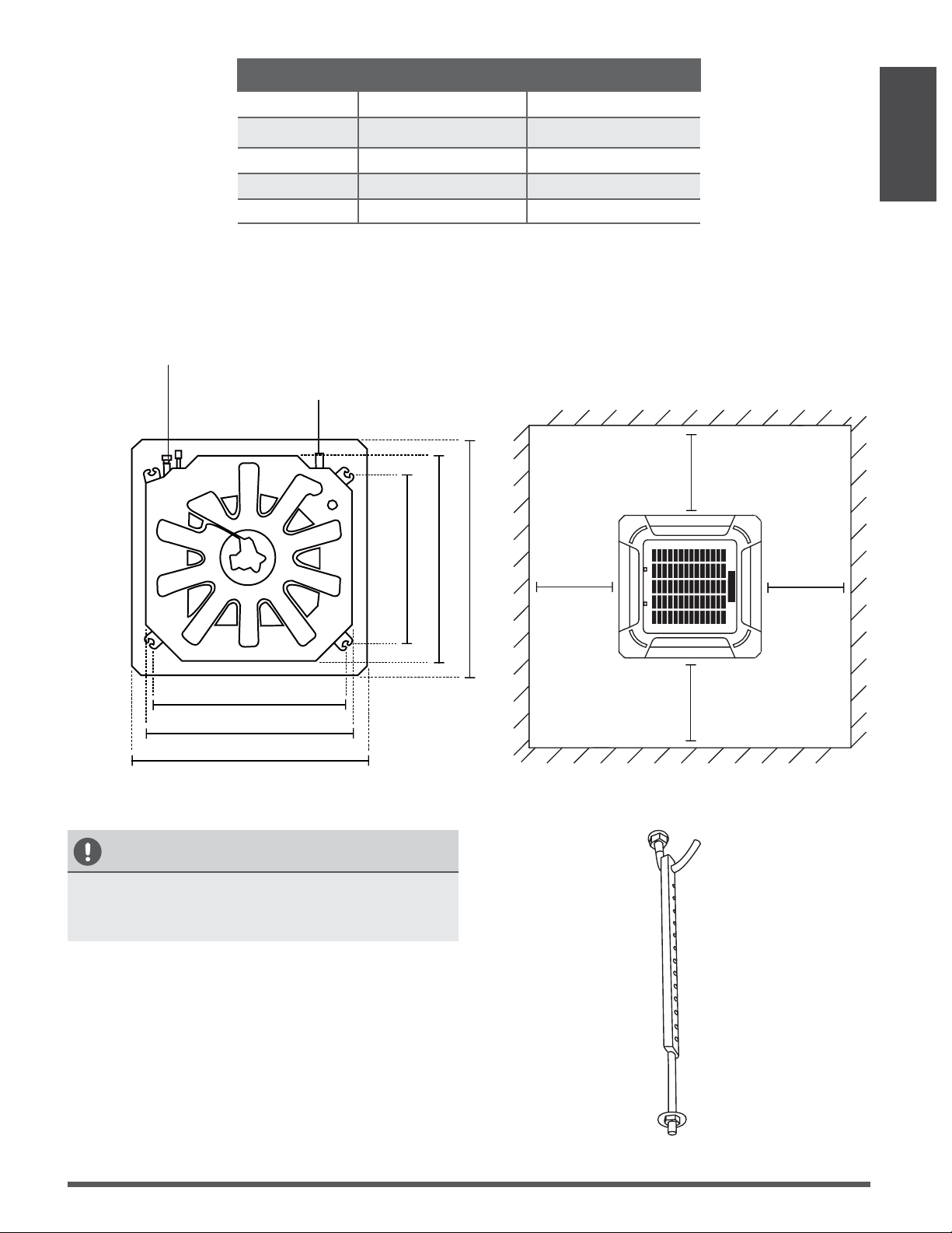
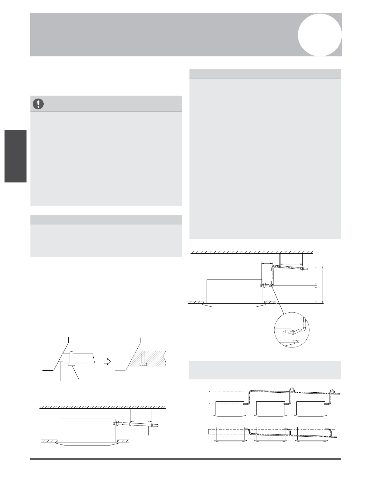
RECOMMENDED DISTANCES BETWEEN THE INDOOR UNIT AND THE CEILING
The distance between the mounted indoor unit and the internal ceiling should meet the following
specifications. (See Fig. 4.2)
Connecting point
of drain pipe
Connecting point of
refrigerant pipe
(liquid side)
Connecting point of
refrigerant pipe
(gas side)
Front panel
Ground
Ceiling board
>2.5m / 8.2’
88cm / 34.5” (Ceiling hole)
Ceiling
Fig. 4.2
Indoor Unit
Installation
Page 9
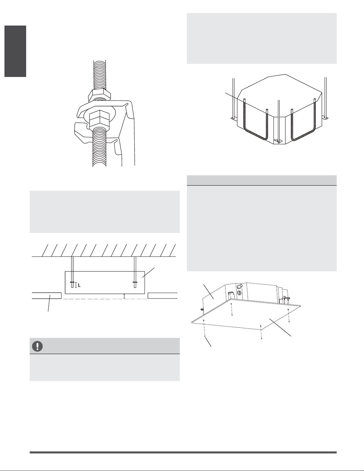
CAUTION
The unit body should align perfectly with the
hole. Ensure that the unit and the hole are the
same size before moving on.
2.
Drill 4 holes 5cm (2”) deep at the ceiling hook
positions in the internal ceiling. Be sure to hold
the drill at a 90° angle to the ceiling.
3.
Using a hammer, insert the ceiling hooks into
the pre-drilled holes. Secure the bolt using the
included washers and nuts.
4.
Install the four suspension bolts (See Fig. 4.4).
Table 4.1: Distance from ceiling relative to height of indoor unit
MODEL Length of A (mm/inch) Length of H (mm/inch)
18 205/8 > 235/9.3
24 205/8 > 235/9.3
30 205/8 > 235/9.3
30-48 245/9.6 > 275/10.8
48-60 287/11.3 > 317/12.5
Step 2: Hang indoor unit.
1.
Use the included paper template to cut a rectangular hole in the ceiling, leaving at least 1m (39”)
on all sides. The hole will be 88x88cm (34.5x34.5”) big. Be sure to mark the areas where ceiling
hook holes will be drilled.
Fig. 4.4
Fig. 4.3
Indoor Unit
Installation
Refrigerant piping side
Drain hose side
78cm / 30” (Suspension bolt)
84cm / 33”(Body)
95cm / 37.4”(Ceiling opening)
68cm / 26”
(Suspension bolt)
84cm / 33” (Body)
95cm / 37.4” (Ceiling opening)
>1m / 39”
>1m / 39”
>1m / 39”
>1m / 39”
Page 10
5. Mount the indoor unit. You will need two
people to lift and secure it. Insert suspension
bolts into the unit’s hanging holes. Fasten
them using the included washers and nuts
(See Fig. 4.5).
Fig. 4.5
NOTE: The bottom of the unit should be
10 - 18mm (0.4-0.7”) higher than the ceiling
board. Generally, L (indicated in Fig. 4.6) should
be half the length of the suspension bolt or long
enough to prevent the nuts from coming o.
Fig. 4.6
CAUTION
Ensure that the unit is completely level.
Improper installation can cause the drain pipe to
back up into the unit or water leakage.
Indoor Unit
Installation
Wall
Ceiling board
Main body
10 - 18mm (0.4-0.7”)
L
NOTE: Ensure that the indoor unit is level. The
unit is equipped with a built-in drain pump and
oat switch. If the unit is tilted against the
direction of condensate ows (the drainpipe
side is raised), the oat switch may malfunction
and cause water to leak.
Water level
Fig. 4.7
NOTE FOR NEW HOME INSTALLATION
When installing the unit in a new home, the
ceiling hooks can be embedded in advance.
Make sure that the hooks do not come loose
due to concrete shrinkage. After installing the
indoor unit, fasten the installation paper
template onto the unit with bolts (M6X12) to
determine in advance the dimension and
position of the opening on the ceiling. Follow
the instructions above for the remainder of the
installation.
Installation template
M6 x 12 Bolts
Main body
Fig. 4.8
Page 11
Outdoor Unit
Installation
Outdoor Unit Installation
Outdoor Unit Installation Instructions
Step 1: Select installation location.
The outdoor unit should be installed in the
location that meets the following requirements:
Place the outdoor unit as close to the indoor
unit as possible.
Ensure that there is enough room for
installation and maintenance.
The air inlet and outlet must not be
obstructed or exposed to strong wind.
Ensure the location of the unit will not be
subject to snowdrifts, accumulation of leaves
or other seasonal debris. If possible, provide
an awning for the unit. Ensure the awning
does not obstruct airflow.
The installation area must be dry and well
ventilated.
There must be enough room to install the
connecting pipes and cables and to access
them for maintenance.
The area must be free of combustible gases
and chemicals.
The pipe length between the outdoor and
indoor unit may not exceed the maximum
allowable pipe length.
If possible, DO NOT install the unit where it
is exposed to direct sunlight.
If possible, make sure the unit is located far
away from your neighbors’ property so that
the noise from the unit will not disturb them.
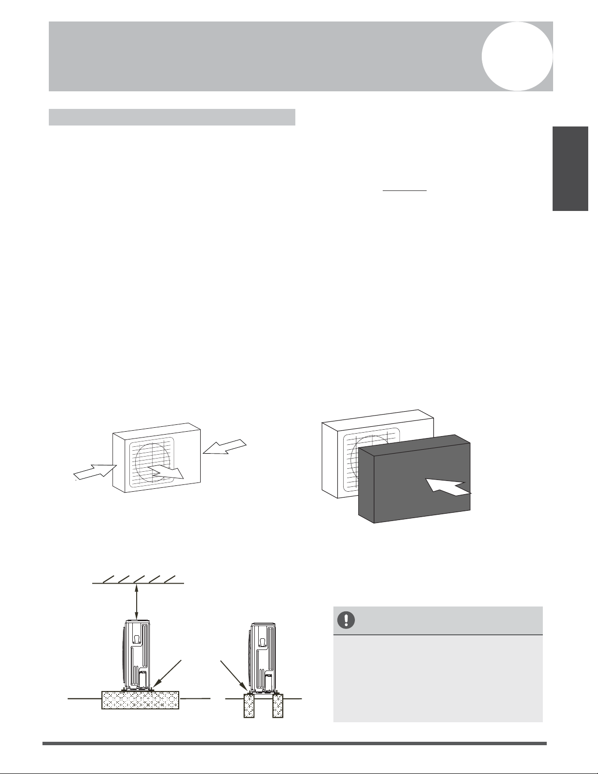
If the location is exposed to strong winds (for
example: near a seaside), the unit must be
placed against the wall to shelter it from the
wind. If necessary, use an awning.
(See Fig. 5.1 & 5.2)
Install the indoor and outdoor units, cables
and wires at least 1 meter from televisions or
radios to prevent static or image distortion.
Depending on the radio waves, a 1 meter
distance may not be enough to eliminate all
interference.
S
trong wind
Strong wind
Strong wind
Fig. 5.1
Fig. 5.2
Step 2: Install outdoor unit.
Fix the outdoor unit with anchor bolts (M10)
>60cm / 23.6”
Fix with bolts
CAUTION
• Be sure to remove any obstacles that
may block air circulation.
• Make sure you refer to Length
Specifications to ensure there is
enough room for installation and
maintenance.
Fig. 5.3
5
√
√
√
√
√
√
√
√
√
√
√
√
Page 12
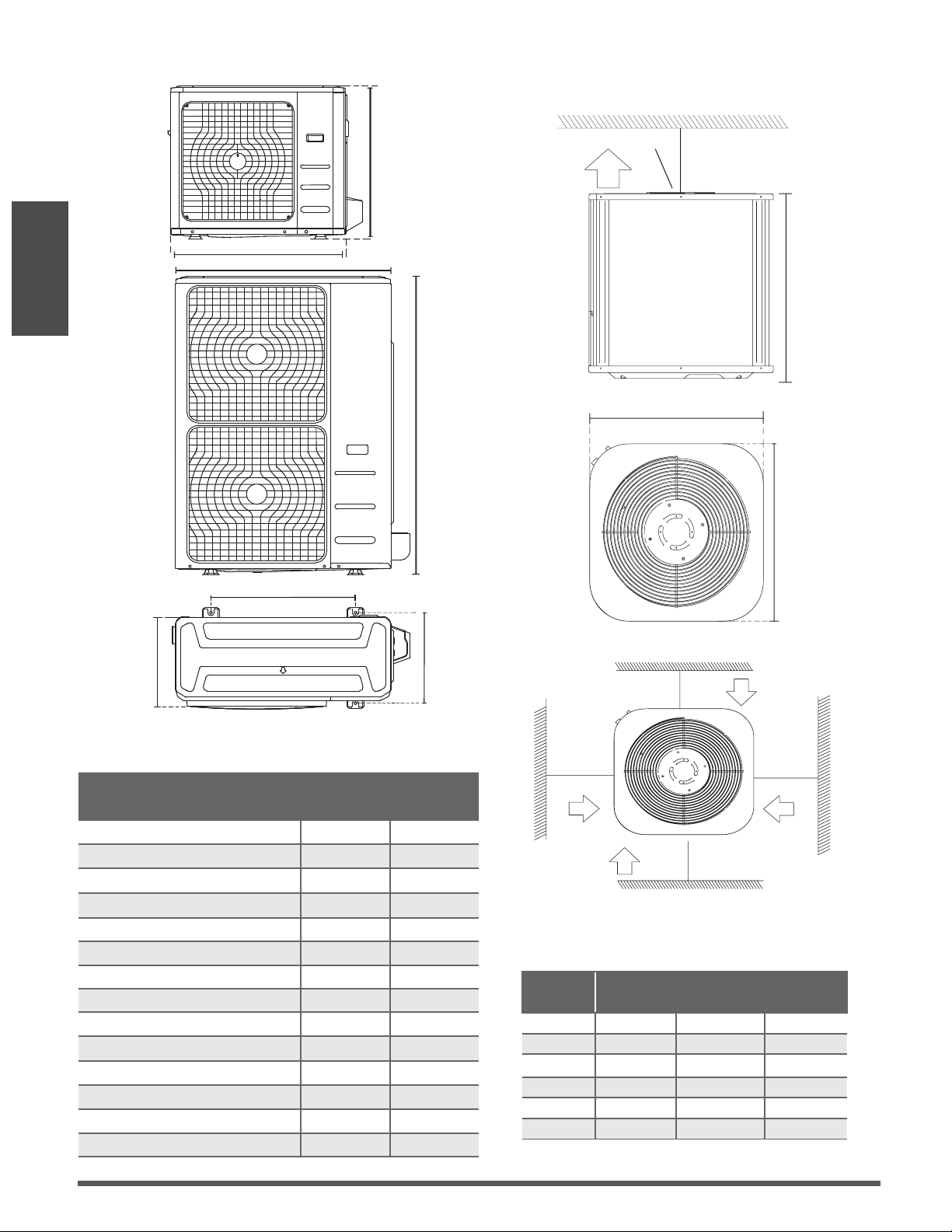
>120cm / 47”
Air Outlet
(Wall or obstacle)
H
D
W
>30cm / 11.8”
Air inlet
Air inlet
Air inlet
Air inlet
(Wall or obstacle)
>30cm / 11.8”
>30cm / 11.8”
>30cm / 11.8”
Table 5.1: Length Specications of Split Type
Outdoor Unit (unit: mm/inch)
Table 5.2: Length Specications of Vertical
Discharge Outdoor Unit (unit: mm/inch)
MODEL
DIMENSIONS
WH D
18 633/25 554/21.8554/21.8
24 633/25 554/21.8554/21.8
36 759/29.8 554/21.8554/21.8
36 633/25 600/23.6600/23.6
48 759/29.8 710/28710/28
60 843/33 710/28710/28
Split Type Outdoor Unit
(Refer to Fig 5.4, 5.5, 5.6, 5.10 and Table 5.1)
Vertical Discharge Type Outdoor Unit
(Refer to Fig 5.7, 5.8, 5.9 and Table 5.2)
Fig. 5.7
Fig. 5.8
Fig. 5.9
Outdoor Unit
Installation
Fig. 5.6
Fig. 5.5
A
B
D
W
H
W
H
Fig. 5.4
Outdoor Unit Dimensions
W x H x D
Mounting Dimensions
Distance A Distance B
760x590x285 (29.9x23.2x11.2) 530 (20.85) 290 (11.4)
810x558x310 (31.9x22x12.2) 549 (21.6) 325 (12.8)
845x700x320 (33.27x27.5x12.6) 560 (22) 335 (13.2)
900x860x315 (35.4x33.85x12.4) 590 (23.2) 333 (13.1)
945x810x395 (37.2x31.9x15.55) 640 (25.2) 405 (15.95)
990x965x345 (38.98x38x13.58) 624 (24.58) 366 (14.4)
946x810x420 (37.24x31.9x16.53) 673 (26.5)
403 (15.87)
946x810x410 (37.24x31.9x16.14) 673 (26.5)
403 (15.87)
952x1333x410 (37.5x52.5x16.14) 634 (24.96)
404 (15.9)
952x1333x415 (37.5x52.5x16.34) 634 (24.96)
404 (15.9)
845x702x363 (33.27x27.6x14.3)
540 (21.26)
350 (13.8)
938x1369x392 (36.93x53.9x15.43) 634 (24.96) 404 (15.9)
900x1170x350 (35.4x46x13.8) 590 (23.2) 378 (14.88)
800x554x333 (31.5x21.8x13.1) 514 (20.24) 340 (13.39)
Page 13
Outdoor Unit
Installation
NOTE:
The minimum distance between the
outdoor unit and walls described in the
installation guide does not apply to airtight
rooms. Be sure to keep the unit unobstructed
in at least two of the three directions (M, N, P)
(See Fig. 5.10)
M
N
P
30 cm
/ 11.8” from back wall
6
0 cm / 23.
6
”
on r
ight
60 cm
/ 23.6
” above
30 cm / 11.8” on left
200 cm / 78” in front
Fig. 5.10
Drain Joint Installation
Before bolting the outdoor unit in place, you
must install the drain joint at the bottom of the
unit. (See Fig. 5.11)
1. Fit the rubber seal on the end of the drain
joint that will connect to the outdoor unit.
2. Insert the drain joint into the hole in the
base pan of the unit.
3. Rotate the drain joint 90° until it clicks in
place facing the front of the unit.
4. Connect a drain hose extension (not
included) to the drain joint to redirect water
from the unit during heating mode.
NOTE: Make sure the water drains to a safe
location where it will not cause water damage
or a slipping hazard.
Seal
Drain joint
(A) (B)
Base pan hole of
outdoor unit
Seal
Fig. 5.11
Notes On Drilling Hole In Wall
You must drill a hole in the wall for the
refrigerant piping, and the signal cable that will
connect the indoor and outdoor units.
1.
Determine the location of the wall hole
based on the location of the outdoor unit.
2.
Using a 65-mm (2.5”) core drill, drill a hole
in the wall.
NOTE: When drilling the wall hole, make
sure to avoid wires, plumbing, and other
sensitive components.
3.
Place the protective wall cu in the hole.
This protects the edges of the hole and will
help seal it when you nish the installation
process.
Page 14
NOTE ON DRAINPIPE INSTALLATION
• When using an extended drainpipe, tighten
the indoor connection with an additional
protection tube to prevent it from pulling
loose.
• The drainpipe should slope downward at a
gradient of at least 1/100 to prevent water
from flowing back into the air conditioner.
• To prevent the pipe from sagging, space
hanging wires every 1-1.5m (40-59”).
• If the outlet of the drainpipe is higher than
the body’s pump joint, provide a lift pipe for
the exhaust outlet of the indoor unit. The
lift pipe must be installed no higher than
75cm (29.5”) from the ceiling board and
the distance between the unit and the lift
pipe must be less than 30cm (11.8”).
Incorrect installation could cause water to
flow back into the unit and flood.
• To prevent air bubbles, keep the drain hose
level or slightly tiled up (<75mm / 3”).
Fig. 6.3
NOTE: When connecting multiple drainpipes,
install the pipes as shown in Fig 6.4.
0-53cm
(20.8”)
≥10cm
(4”)
Fig. 6.4
The drainpipe is used to drain water from the
unit. Improper installation may cause unit and
property damage.
CAUTION
• Insulate all piping to prevent condensation,
which could lead to water damage.
• If the drainpipe is bent or installed
incorrectly, water may leak and cause a
malfunction of the water- level switch.
• In HEAT mode, the outdoor unit will
discharge water. Ensure that the drain hose
is placed in an appropriate area to avoid
water damage and slippage due to frozen
drain water.
• DO NOT pull the drainpipe forcefully as this
could cause it to disconnect.
NOTE ON PURC HASING PIPES
This installation requires a polyethylene tube
(outside diameter = 3.7-3.9cm, inside diameter
= 3.2cm), which can be obtained at your local
hardware store or from your dealer.
Indoor Drainpipe Installation
Install the drainpipe as shown in Figure 6.2.
1.
Cover the drainpipe with heat insulation to
prevent condensation and leakage.
2.
Attach the mouth of the drain hose to the
unit’s outlet pipe. Sheath the mouth of the
hose and clip it rmly with a pipe clasp.
(Fig 6.1)
Drainpipe
connecting port
Drain hose
Metal clamp
Insulation
Fig. 6.1
Drainpipe Installation
6
Drainpipe
Installation
Downward slope
1/100
1-1.5m
(39-59”)
Fig. 6.2
≤75cm
(29.5”)
Ceiling
1 - 1.5m
(39-59”)
0 - 75mm
(3”)
≤30cm (11.8”)
≤53cm
(20.8”)
22cm
(8.6”)
Page 15
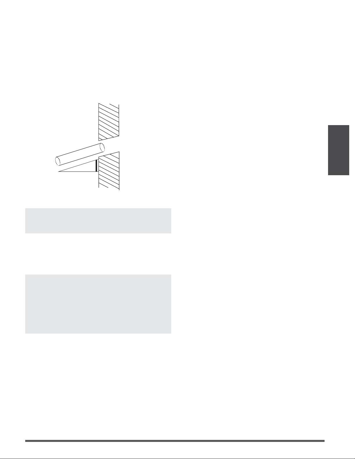
3.
Using a 65-mm (2.5”) core drill, drill a hole in
the wall. Make sure that the hole is drilled at a
slight downward angle, so that the outdoor
end of the hole is lower than the indoor end
by about 12mm (0.5”). This will ensure proper
water drainage (See Fig. 6.5). Place the
protective wall cu in the hole. This protects
the edges of the hole and will help seal it
when you nish the installation process.
Wall
IndoorOutdoor
≈ 12mm / 0.5 inch
Fig. 6.5
NOTE: When drilling the wall hole, make sure to
avoid wires, plumbing, and other sensitive
components.
4.
Pass the drain hose through the wall hole.
Make sure the water drains to a safe location
where it will not cause water damage or a
slipping hazard.
NOTE: The drainpipe outlet should be at least
5cm (1.9”) above the ground. If it touches the
ground, the unit may become blocked and
malfunction. If you discharge the water directly
into a sewer, make sure that the drain has a U
or S pipe to catch odors that might otherwise
come back into the house.
Drainpipe
Installation
Page 16
Refrigerant Piping
Connection
Refrigerant Piping Connection
Safety Precautions
WARNING
• All eld piping must be completed by a
licensed technician and must comply with
the local and national regulations.
• When the air conditioner is installed in a
small room, measures must be taken to
prevent the refrigerant concentration in
the room from exceeding the safety limit
in the event of refrigerant leakage. If the
refrigerant leaks and its concentration
exceeds its proper limit, hazards due to
lack of oxygen may result.
• When installing the refrigeration system,
ensure that air, dust, moisture or foreign
substances do not enter the refrigerant
circuit. Contamination in the system may
cause poor operating capacity, high
pressure in the refrigeration cycle,
explosion or injury.
• Ventilate the area immediately if there is
refrigerant leakage during the installation.
Leaked refrigerant gas is both toxic and
flammable. Ensure there is no refrigerant
leakage after completing the installation
work.
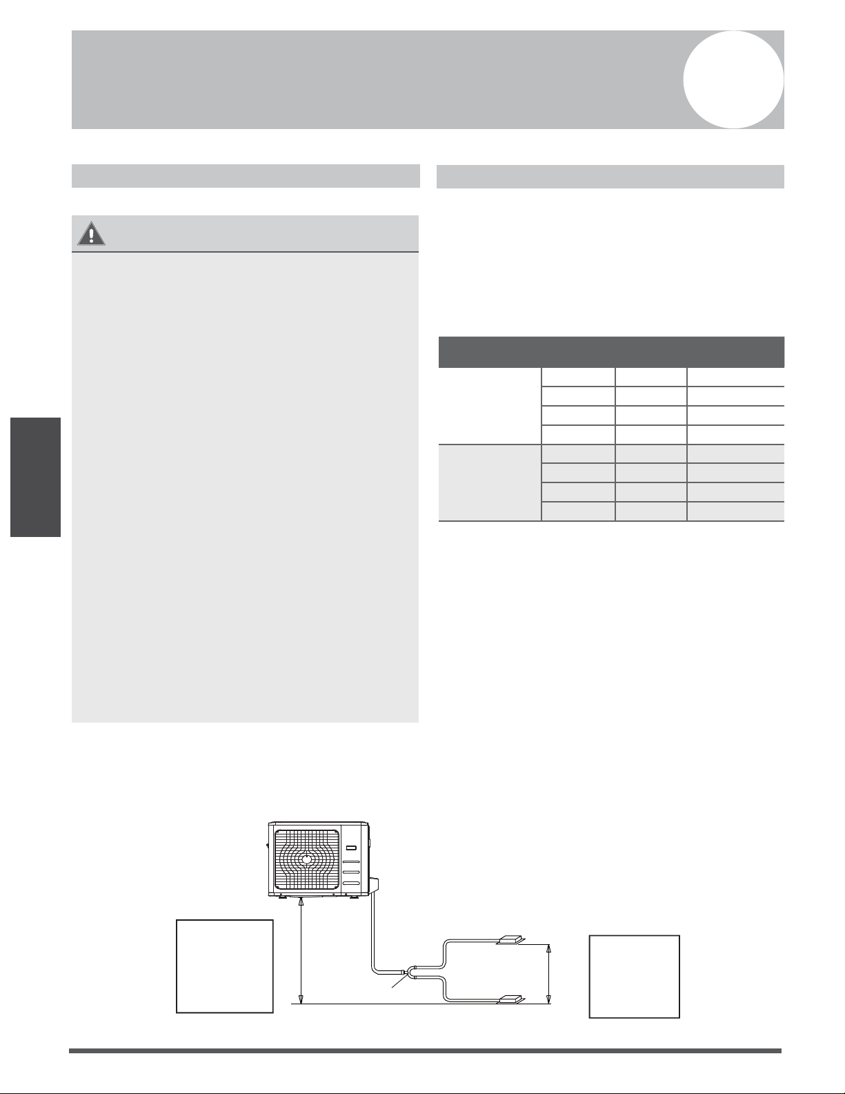
Notes On Pipe Length and Elevation
Ensure that the length of the refrigerant pipe, the
number of bends, and the drop height between
the indoor and outdoor units meets the
requirements shown in Table 7.1:
Table 7.1: The Maximum Length And Drop
Height Based on Models. (Unit: m/ft.)
Type of model Capacity
(Btu/h)
Length of
piping
Maximum drop
height
North America,
Australia and the
eu frequency
conversion Split
Ty p e
<15K 25/82 10/32.8
15K - <24K 30/98.4 20/65.6
24K - <36K 50/164 25/82
36K - 60K 65/213 30/98.4
Other Split Type
12K 15/49 8/26
18K-24K 25/82 15/49
30K-36K 30/98.4 20/65.6
42K-60K 50/164 30/98.4
Refrigerant Piping with Twin Indoor Units
When installing multiple indoor units to a single outdoor unit, ensure that the length of the r
efrigerant pipe and the drop height between the indoor and outdoor units meets the following
requirements:
L
L1
L2
H2
The line branch pipe
Indoor unit
Outdoor unit
H1
Indoor unit
The drop height
between two
indoor units
must be less
than or equal to
50cm (19.6”)
The drop height
between indoor
unit
and outdoor unit
must be less than
or equal to 20m
(65.6’)
Fig. 7.1
7
Page 17
Refrigerant Piping
Connection
Table 7.2
Permitted length
Piping
length
Total piping length 18K+18K 30/98’ L+Max
(L1, L2)
24K+24K
30K+30K
50/164’
(farthest distance from
the line pipe branch)
15/49’ L1, L2
(farthest distance from
the line pipe branch)
10/32.8’ L1-L2
Drop
height
Drop height between
indoor and outdoor unit
20/65.6’ H1
Drop height between
two indoor units
0.5/1.6’ H2
Refrigerant Piping Connection Instructions
CAUTION
• The branching pipe must be installed
horizontally. An angle of more than 10° may
cause malfunction.
• DO NOT install the connecting pipe until
both indoor and outdoor units have been
installed.
• Insulate both the gas and liquid piping to
prevent water leakage.
Step1: Cut pipes
When preparing refrigerant pipes, take extra
care to cut and flare them properly. This will
ensure efficient operation and minimize the
need for future maintenance.
1.
Measure the distance between the indoor
and outdoor units.
2.
Using a pipe cutter, cut the pipe a little
longer than the measured distance.
CAUTION
DO NOT deform pipe while cutting. Be extra
careful not to damage, dent, or deform the pipe
while cutting. This will drastically reduce the
heating efficiency of the unit.
1.
Make sure that the pipe is cut at a perfect 90°
angle. Refer to Fig. 7.2 for examples of bad cuts
Oblique
Rough
Warped
90°
Fig. 7.2
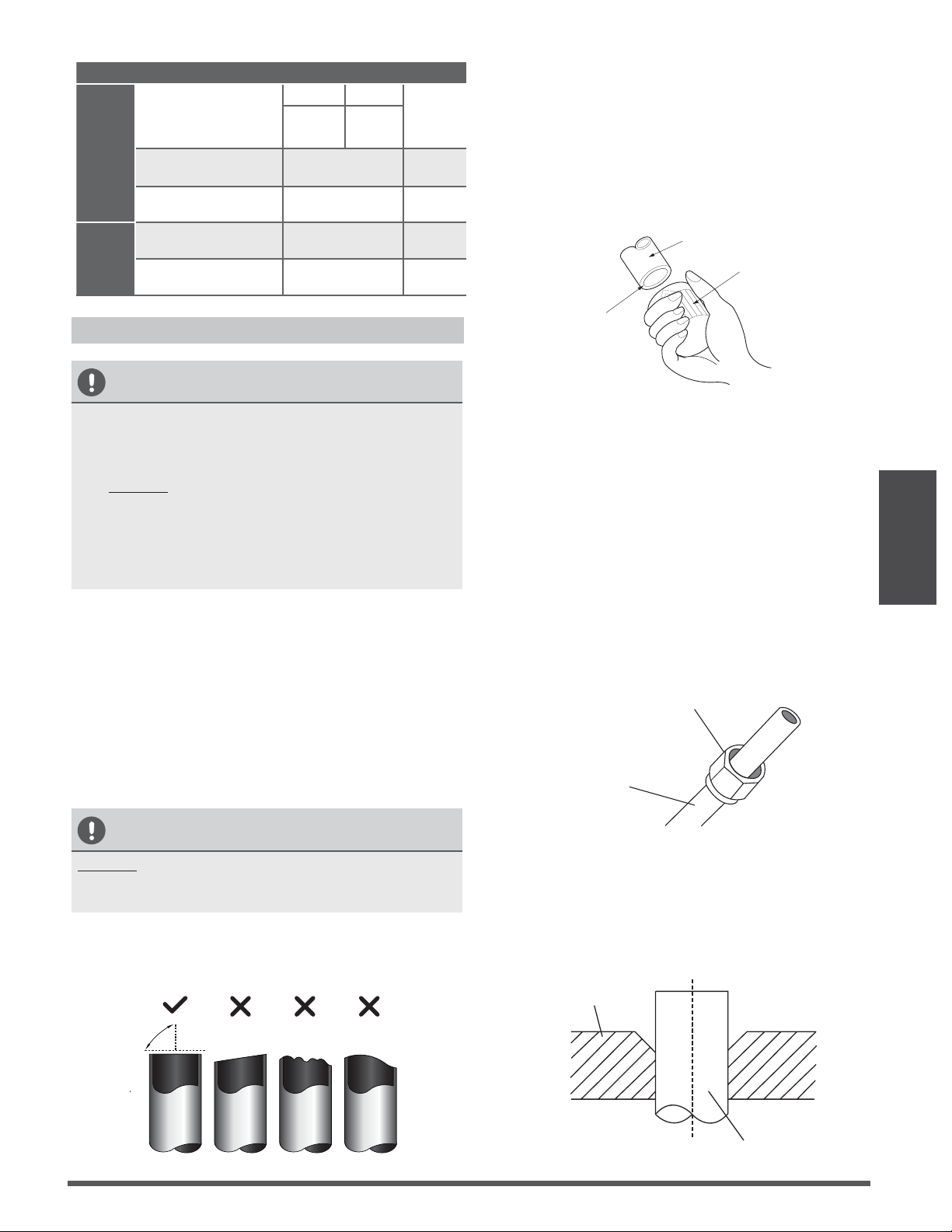
Step 2: Remove burrs.
Burrs can aect the air-tight seal of refrigerant
piping connection. They must be completely
removed.
1.
Hold the pipe at a downward angle to
prevent burrs from falling into the pipe.
2.
Using a reamer or deburring tool, remove
all burrs from the cut section of the pipe.
Pipe
Reamer
Point dow n
Fig. 7.3
Step 3: Flare pipe ends
Proper flaring is essential to achieve an airtight
seal.
1.
After removing burrs from cut pipe, seal
the ends with PVC tape to prevent foreign
materials from entering the pipe.
2.
Sheath the pipe with insulating material.
3.
Place flare nuts on both ends of pipe.
Make sure they are facing in the right
direction, because you can’t put them on
or change their direction after flaring. See
Fig. 7.4
Flare nut
Copper pipe
Fig. 7.4
4.
Remove PVC tape from ends of pipe when
ready to perform flaring work.
5. Clamp flare form on the end of the pipe.
The end of the pipe must extend beyond
the flare form.
Flare form
Pipe
Fig. 7.5
Page 18
Refrigerant Piping
Connection
6.
Place flaring tool onto the form.
7.
Turn the handle of the flaring tool
clockwise until the pipe is fully flared. Flare
the pipe in accordance with the dimensions
shown in table 7.5.
Table 7.5: PIPING EXTENSION BEYOND FLARE
FORM
Pipe
gauge
Tightening
torque
Flare dimension (A)
(Unit: mm/Inch)
Flare shape
Min. Max .
Ø 6.4
14.2-17.2 N.m
(144-176 kgf.cm)
8.3/0.3 8.3/0.3
R0.4~0. 8
45
°
±
2
90
°
±
4
A
Fig. 7.6
Ø 9.5
32.7-39.9 N.m
(333-407 kgf.cm)
12.4/0.48 12.4/0.48
Ø 12.7
49.5-60.3 N.m
(504-616 kgf.cm)
15.4/0.6 15.8/0.6
Ø 15.9
61.8-75.4 N.m
(630-770 kgf.cm)
18.6/0.7 19/0.74
Ø 19.1
97.2-118.6 N.m
(990-1210 kgf.
cm)
22.9/0.9 23.3/0.91
8. Remove the flaring tool and flare form,
then inspect the end of the pipe for cracks
and even flaring.
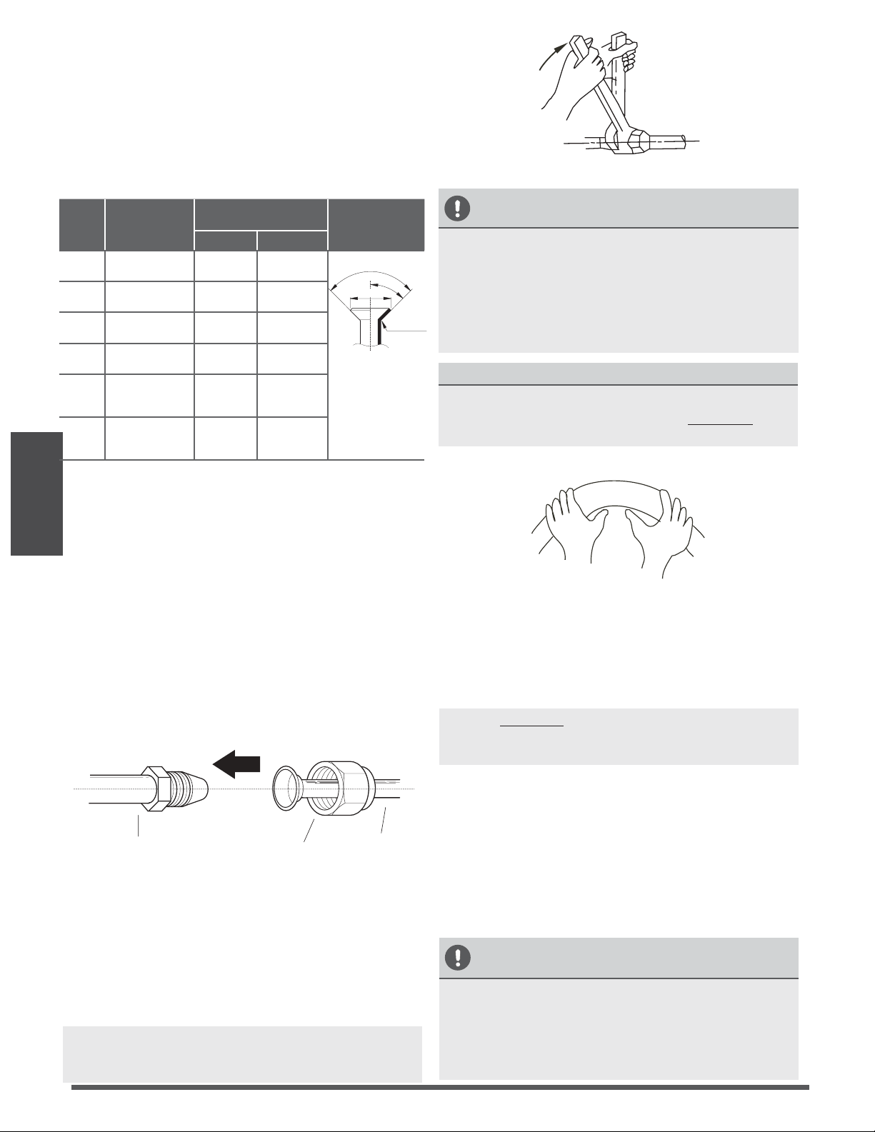
Step 4: Connect pipes
Connect the copper pipes to the indoor unit first,
then connect it to the outdoor unit. You should
first connect the low-pressure pipe, then the high-
pressure pipe.
1.
When connecting the flare nuts, apply a
thin coat of refrigeration oil to the flared
ends of the pipes.
2.
Align the center of the two pipes that you
will connect.
Indoor unit tubing
Flare nut
Pipe
Fig. 7.7
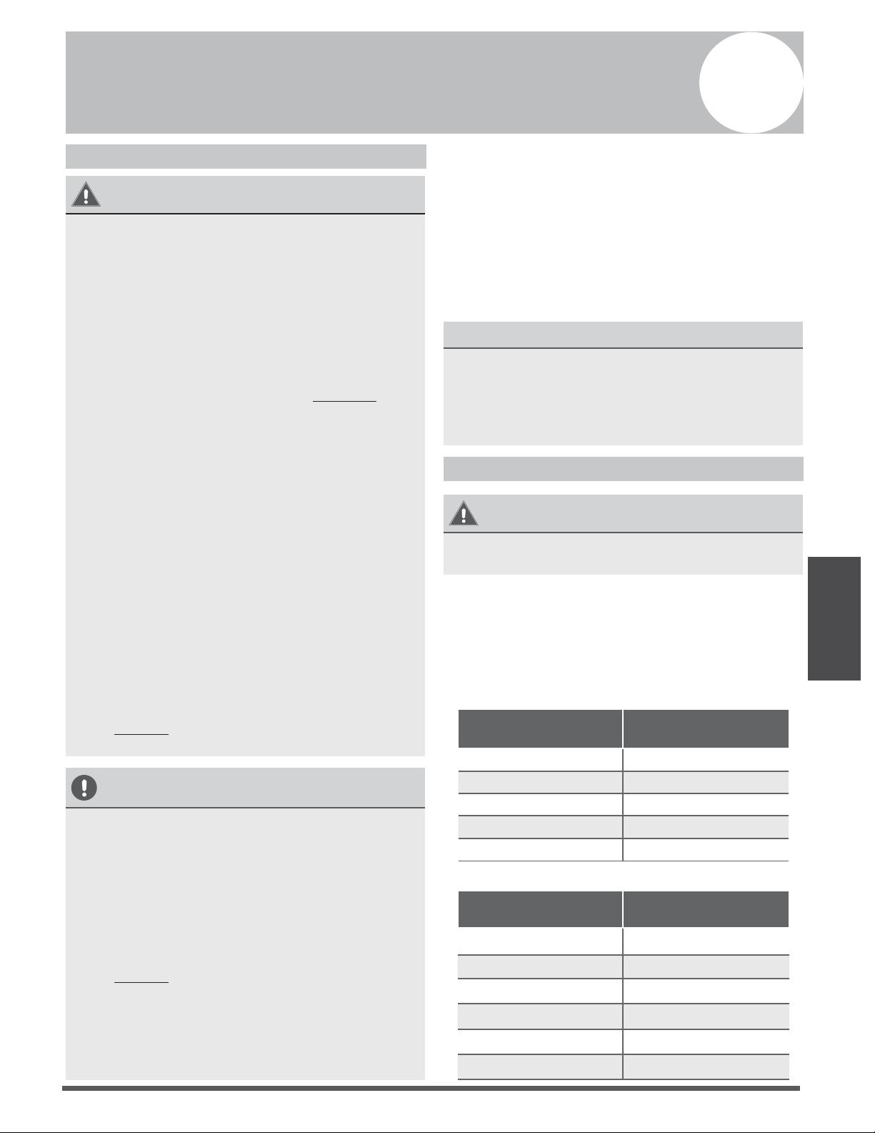
3.
Tighten the flare nut as tightly as possible
by hand.
4.
Using a spanner, grip the nut on the unit
tubing.
5.
While firmly gripping the nut, use a torque
wrench to tighten the flare nut according
to the torque values in table 7.5.
NOTE: Use both a spanner and a torque wrench
when connecting or disconnecting pipes to/from
the unit.
Fig. 7.8
CAUTION
• Ensure to wrap insulation around the piping.
Direct contact with the bare piping may result
in burns or frostbite.
•
Make sure the pipe is properly connected.
Over tightening may damage the bell mouth
and under tightening may lead to leakage.
NOTE ON MINIMUM BEND RADIUS
Carefully bend the tubing in the middle
according to the diagram below. DO NOT bend
the tubing more than 90° or more than 3 times.
Bend the pipe with thumb
min-radius 10cm (3.9”)
Fig. 7.9
6.
After connecting the copper pipes to the
indoor unit, wrap the power cable, signal
cable and the piping together with
binding tape.
NOTE:
DO NOT intertwine signal cable with
other wires. While bundling these items
together, do not intertwine or cross the signal
cable with any other wiring.
7.
Thread this pipeline through the wall and
connect it to the outdoor unit.
8.
Insulate all the piping, including the valves
of the outdoor unit.
9.
Open the stop valves of the outdoor unit
to start the flow of the refrigerant between
the indoor and outdoor unit.
CAUTION
Check to make sure there is no refrigerant leak
after completing the installation work. If there is
a refrigerant leak, ventilate the area immediately
and evacuate the system (refer to the Air
Evacuation section of this manual).
Ø 22
109.5-133.7 N.m
(1117-1364 kgf.
cm)
27/1.06 27.3/1.07
Page 19
Wiring
TAKE NOTE OF FUSE SPECIFICATIONS
The air conditioner s circuit board(PCB) is
designed with a fuse to provide overcurrent
protection. The specications of the fuse are
printed on the circuit board, such as:
T3.15A/250VAC, T5A/250VAC, etc.
Wiring
Safety Precautions
WARNING
• Be sure to disconnect the power supply
before working on the unit.
• All electrical wiring must be done
according to local and national regulations.
• Electrical wiring must be done by a
qualied technician. Improper connections
may cause electrical malfunction, injury
and fire.
• An independent circuit and single outlet
must be used for this unit. DO NOT plug
another appliance or charger into the
same outlet.If the electrical circuit capacity
is not enough or there is a defect in the
electrical work, it can lead to shock, fire,
unit and property damage.
• Connect the power cable to the terminals
and fasten it with a clamp. An insecure
connection may cause fire.
• Make sure that all wiring is done correctly
and the control board cover is properly
installed. Failure to do so can cause
overheating at the connection points, fire,
and electrical shock.
• Ensure that main supply connection is
made through a switch that disconnects
all poles, with contact gap of a least 3mm
(0.118”).
• DO NOT modify the length of the power
cord or use an extension cord.
CAUTION
• Connect the outdoor wires before
connecting theindoor wires.
• Make sure you ground the unit. The
grounding wire should be away from gas
pipes, water pipes, lightning rods,
telephone or other grounding wires.
Improper grounding may cause electrical
shock.
• DO NOT connect the unit with the power
source until all wiring and piping is
completed.
• Make sure that you do not cross your
electrical wiring with your signal wiring, as
this can cause distortion and interference.
Follow these instructions to prevent distortion
when the compressor starts:
• The unit must be connected to the main
outlet. Normally, the power supply must
have a low output impedance of 32 ohms.
• No other equipment should be connected
to the same power circuit.
• The unit’s power information can be found
on the rating sticker on the product.
Outdoor Unit Wiring
WARNING
Before performing any electrical or wiring work,
turn o the main power to the system.
1.
Prepare the cable for connection
a.
You must first choose the right cable size
before preparing it for connection. Be sure
to use H07RN-F cables.
Table 8.1: Minimum Cross-Sectional Area
of Power and Signal Cables North America
Rated Current of
Appliance (A)
AWG
718
7 - 13 16
13 - 18 14
18 - 25 12
25 - 30 10
Table 8.2: Other Regions
Rated Current of
Appliance (A)
Nominal Cross-Sectional
Area (mm²)
6 0.75
6 - 10 1
10 - 16 1.5
16 - 25 2.5
25- 32 4
32 - 45 6
8
Page 20
b. Using wire strippers, strip the rubber jacket
from both ends of signal cable to reveal
about 15cm (5.9”) of the wires inside.
c.
Strip the insulation from the ends of the
wires.
d.
Using a wire crimper, crimp u-lugs on the
ends of the wires.
NOTE: While connecting the wires, please
strictly follow the wiring diagram (found inside
the electrical box cover).
2.
Remove the electric cover of the outdoor unit.
If there is no cover on the outdoor unit,
disassemble the bolts from the maintenance
board and remove the protection board.
(See Fig. 8.1, 8.2)
Cover
Screw
Fig. 8.1
Protection Board
Fig. 8.2
3.
Connect the u-lugs to the terminals
Match the wire colors/labels with the labels
on the terminal block, and rmly screw the
u-lug of each wire to its corresponding
terminal.
4.
Clamp down the cable with designated cable
clamp.
5.
Insulate unused wires with electrical tape.
Keep them away from any electrical or metal
parts.
6.
Reinstall the cover of the electric control box.
Indoor Unit Wiring
1.
Prepare the cable for connection
a.
Using wire strippers, strip the rubber jacket
from both ends of signal cable to reveal
about 15cm (5.9”) of the wires inside.
b.
Strip the insulation from the ends of the
wires.
c.
Using wire crimper, crimp the u-lugs to the
ends of the wires.
2.
Open the front panel of the indoor unit. Using
a screwdriver, remove the cover of the electric
control box on your indoor unit.
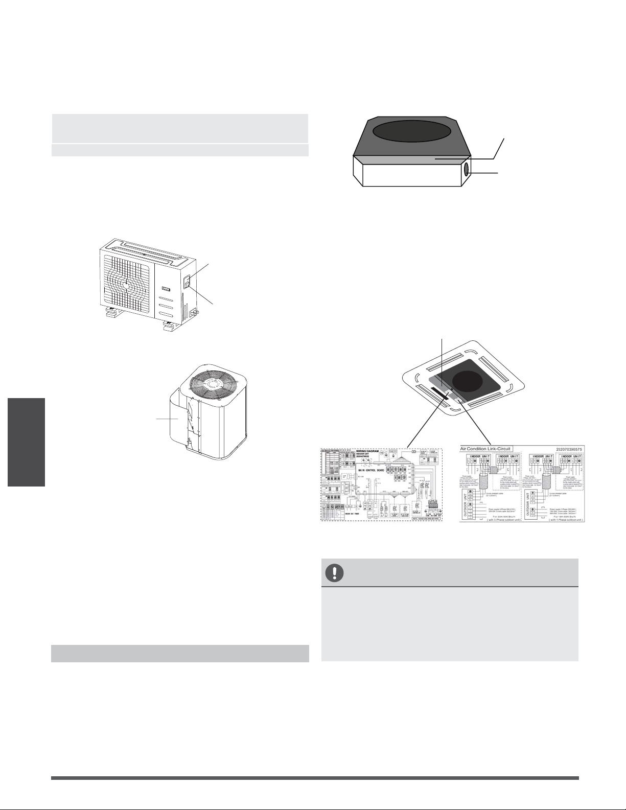
3.
Thread the power cable and the signal cable
through the wire outlet.
Wire outlet
Control box
Fig. 8.3
4.
Connect the u-lugs to the terminals.
Match the wire colors/labels with the labels on
the terminal block, and firmly screw the u-lug
of each wire to its corresponding terminal.
Refer to the Serial Number and Wiring Diagram
located on the cover of the electric control box.
Connective wiring diagram
Wiring diagram
Control box
CAUTION
• While connecting the wires, please strictly
follow the wiring diagram.
• The refrigerant circuit can become very
hot. Keep the interconnection cable away
from the copper tube.
5. Clamp down cable with the designated cable
clamp to secure it in place. The cable should
not be loose, and should not pull on the u-lugs.
6. Reinstall the electric box cover and the front
panel of the indoor unit.
Wiring
Fig. 8.4
Page 21
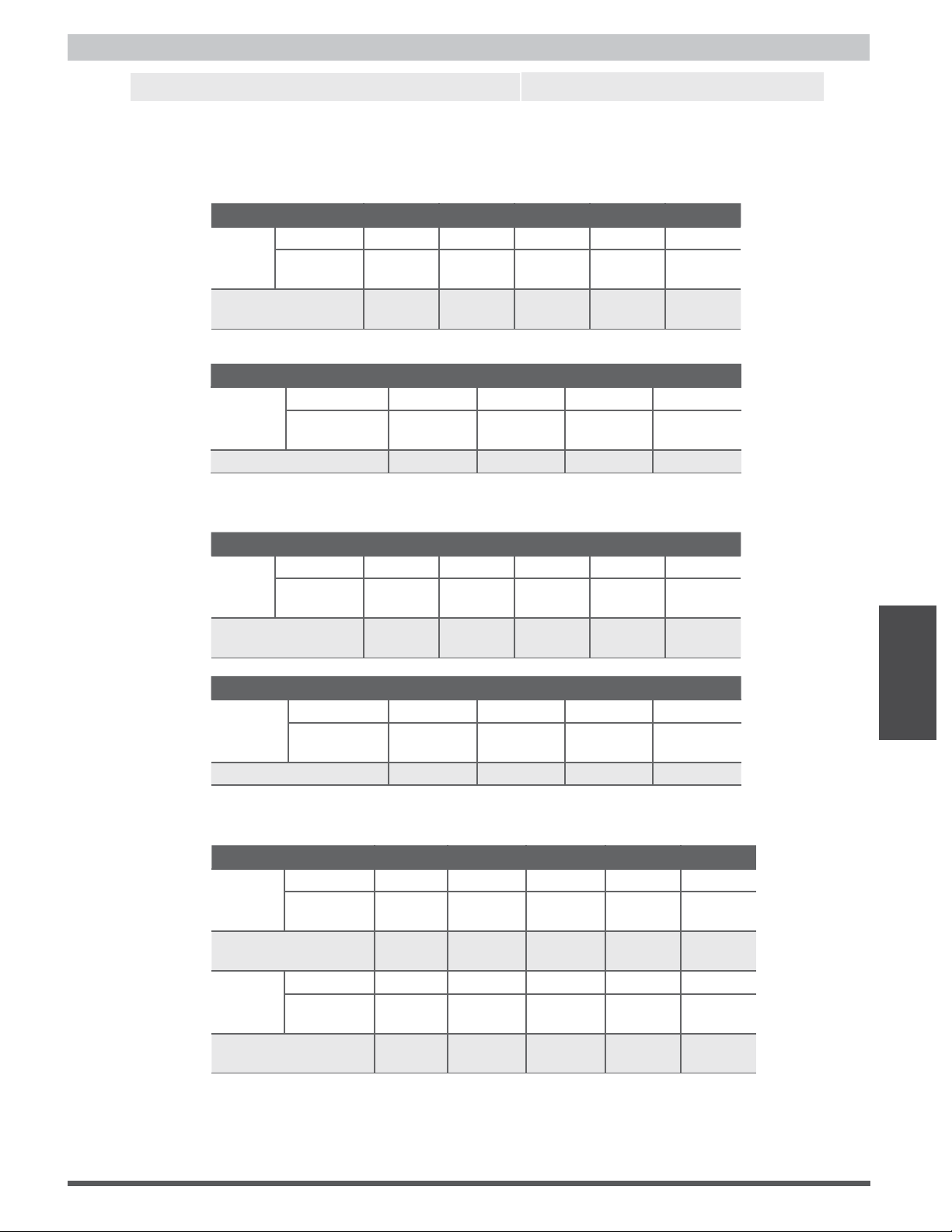
Power Specications
Wiring
Indoor Power Supply Specications
MODEL
(Btu/h)
18K 19K~24K 25K~36K 37K~48K 49K~60K
POWER
PHASE 1 Phase 1 Phase 1 Phase 1 Phase 1 Phase
FREQUENCY
AND VOLT
208-240V 208-240V 208-240V 208-240V 208-240V
CIRCUIT BREAKER/
FUSE(A)
25/20 32/25 50/40 70/55 70/60
MODEL
(Btu/h)
36K 37K~60K 36K 37K~60K
POWER
PHASE 3 Phase 3 Phase 3 Phase 3 Phase
FREQUENCY
AND VOLT
380-420V 380-420V 208-240V 208-240V
CIRCUIT BREAKER/FUSE(A) 25/20 32/25 32/25 45/35
Outdoor Power Supply Specications
MODEL
(Btu/h)
36K 37K~60K 36K 37K~60K
POWER
PHASE 3 Phase 3 Phase 3 Phase 3 Phase
FREQUENCY
AND VOLT
380-420V 380-420V 208-240V 208-240V
CIRCUIT BREAKER/FUSE(A) 25/20 32/25 32/25 45/35
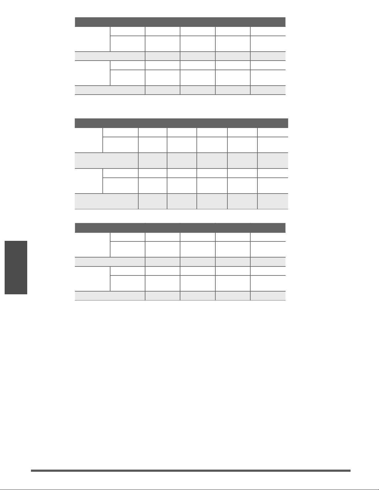
Independent Power Supply Specications
MODEL
(Btu/h)
18K 19K~24K 25K~36K 37K~48K 49K~60K
POWER
(indoor)
PHASE 1 Phase 1 Phase 1 Phase 1 Phase 1 Phase
FREQUENCY
AND VOLT
208-240V 208-240V
208-
240V
208-240V 208-240V
CIRCUIT BREAKER/
FUSE(A)
15/10 15/10 15/10 15/10 15/10
POWER
(outdoor)
PHASE 1 Phase 1 Phase 1 Phase 1 Phase 1 Phase
FREQUENCY
AND VOLT
208-240V 208-240V 208-240V
208-240V
208-240V
CIRCUIT BREAKER/
FUSE(A)
25/20 32/25 50/40 70/55 70/60
Wiring
MODEL
(Btu/h)
18K 19K~24K 25K~36K 37K~48K 49K~60K
POWER
PHASE 1 Phase 1 Phase 1 Phase 1 Phase 1 Phase
FREQUENCY
AND VOLT
208-240V 208-240V 208-240V 208-240V 208-240V
CIRCUIT BREAKER/
FUSE(A)
25/20 32/25 50/40 70/55 70/60
NOTE: Electric auxiliary heating type circuit breaker/fuse need to add more than 10 A.
Page 22
Wiring
MODEL
(Btu/h)
36K 37K~60K 36K 37K~60K
POWER
(indoor)
PHASE 1 Phase 1 Phase 1 Phase 1 Phase
FREQUENCY
AND VOLT
208-240V 208-240V 208-240V 208-240V
CIRCUIT BREAKER/FUSE(A) 15/10 15/10 15/10 15/10
POWER
(outdoor)
PHASE 3 Phase 3 Phase 3 Phase 3 Phase
FREQUENCY
AND VOLT
380-420V 380-420V 208-240V 208-240V
CIRCUIT BREAKER/FUSE(A) 25/20 32/25 32/25 45/35
Inverter Type A/C Power Specications
MODEL
(Btu/h)
18K 19K~24K 25K~36K 37K~48K 49K~60K
POWER
(indoor)
PHASE 1 Phase 1 Phase 1 Phase 1 Phase 1 Phase
FREQUENCY
AND VOLT
220-240V 220-240V 220-240V 220-240V 220-240V
CIRCUIT BREAKER/
FUSE(A)
15/10 15/10 15/10 15/10 15/10
POWER
(outdoor)
PHASE 1 Phase 1 Phase 1 Phase 1 Phase 1 Phase
FREQUENCY
AND VOLT
208-240V 208-240V 208-240V 208-240V 208-240V
CIRCUIT BREAKER/
FUSE(A)
25/20 25/20 40/30 50/40 50/40
MODEL
(Btu/h)
36K 37K~60K 36K 37K~60K
POWER
(indoor)
PHASE 1 Phase 1 Phase 1 Phase 1 Phase
FREQUENCY
AND VOLT
220-240V 220-240V 220-240V 220-240V
CIRCUIT BREAKER/FUSE(A) 15/10 15/10 15/10 15/10
POWER
(outdoor)
PHASE 3 Phase 3 Phase 3 Phase 3 Phase
FREQUENCY
AND VOLT
380-420V 380-420V 208-240V 208-240V
CIRCUIT BREAKER/FUSE(A) 25/20 32/25 32/25 40/30
Page 23
Air Evacuation
Air Evacuation
Safety Precautions
CAUTION
• Use a vacuum pump with a gauge reading
lower than -0.1MPa and an air discharge capacity
above 40L/min.
• The outdoor unit does not need vacuuming.
DO NOT open the outdoor unit’s gas and
liquid stop valves.
• Ensure that the Compound Meter reads
-0.1MPa or below after 2 hours. If after
three hours of operation and the gauge
reading is still above -0.1MPa, check if there
is a gas leak or water inside the pipe. If
there is no leakage, perform another
evacuation for 1 or 2 hours.
• DO NOT use refrigerant gas to evacuate the
system.
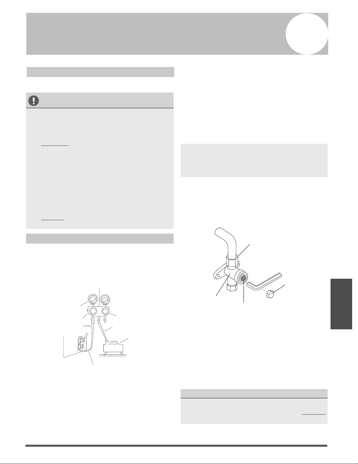
Evacuation Instructions
Before using manifold gauge and vacuum pump,
read their operation manuals to familiarize
yourself with how to use them properly.
Manifold Gauge
Compound gauge
-76cmHg
Low pressure valve
High pressure valve
Charge hose
Charge hose
Vacuum pump
Pressure gauge
Low pressure valve
Fig. 9.1
1.
Connect the charge hose of the manifold
gauge to service port on the outdoor unit’s
low pressure valve.
2.
Connect another charge hose from the
manifold gauge to the vacuum pump.
3.
Open the Low Pressure side of the manifold
gauge.Keep the High Pressure side closed.
4.
Turn on the vacuum pump to evacuate the
system.
5.
Run the vacuum for at least 15 minutes, or
until the Compound Meter reads -76cmHG
(-1x10⁵Pa).
6.
Close the Low Pressure side of the manifold
gauge, and turn o the vacuum pump.
7.
Wait for 5 minutes, then check that there has
been no change in system pressure.
NOTE: If there is no change in system pressure,
unscrew the cap from the packed valve (high
pressure valve). If there is a change in system
pressure, there may be a gas leak.
8.
Insert hexagonal wrench into the packed valve
(high pressure valve) and open the valve by
turning the wrench in a 1/4 counterclockwise
turn. Listen for gas to exit the system, then
close the valve after 5 seconds.
Flare nut
Cap
Valve body
Valve stem
Fig. 9.2
9. Watch the Pressure Gauge for one minute to
make sure that there is no change in pressure.
The Pressure Gauge should read slightly higher
than atmospheric pressure.
10.
Remove the charge hose from the service port.
11.
Using hexagonal wrench, fully open both the
high pressure and low pressure valves.
OPEN VALVE STEMS GENTLY
When opening valve stems, turn the hexagonal
wrench until it hits against the stopper. DO NOT
try to force the valve to open further.
12. Tighten valve caps by hand, then tighten it
using the proper tool.
9
Page 24
Air Evacuation
Note On Adding Refrigerant
CAUTION
• Refrigerant charging must be performed after wiring, vacuuming and the leak test.
• DO NOT exceed the maximum allowable quantity of refrigerant or overcharge the system.
Doing so can damage or impact the unit’s function.
• Charging with unsuitable substances may cause explosions or accidents. Ensure that the
appropriate refrigerant is used.
• Refrigerant containers must be opened slowly. Always use protective gear when charging the
system.
•
DO NOT mix refrigerants types.
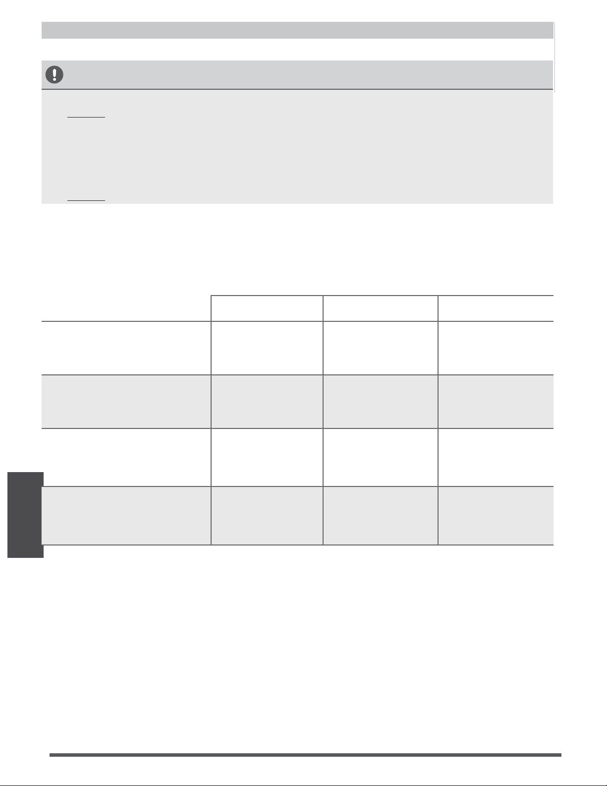
Some systems require additional charging depending on pipe lengths. The standard pipe length
varies according to local regulations. For example, in North America, the standard pipe length is
7.5m (25’) In other areas, the standard pipe length is 5m (16‘). The additional refrigerant to be
charged can be calculated using the following formula:
Liquid Side Diameter
φ6.35(1/4”) φ9.52(3/8”) φ12.7(1/2”)
R22
(orice tube in the indoor unit):
(Total pipe length -
standard pipe length)x
30g (0.32oZ)/m(ft)
(Total pipe length -
standard pipe length)x
65g(0.69oZ)/m(ft)
(Total pipe length -
standard pipe length)x
115g(1.23oZ)/m(ft)
R22
(orice tube in the outdoor unit):
(Total pipe length -
standard pipe length)
x15g(0.16oZ)/m(ft)
(Total pipe length -
standard pipe length)
x30(0.32oZ)/m(ft)
(Total pipe length -
standard pipe length)
x60g(0.64oZ)/m(ft)
(Total pipe length -
standard pipe length)
x65g(0.69oZ)/m(ft)
R410A:
(orice tube in the indoor unit):
(Total pipe length -
standard pipe length)
x30g(0.32oZ)/m(ft)
(Total pipe length -
standard pipe length)
x65g(0.69oZ)/m(ft)
(Total pipe length -
standard pipe length)
x115g(1.23oZ)/m(ft)
R410A:
(orice tube in the outdoor unit):
(Total pipe length -
standard pipe length)
x15g(0.16oZ)/m(ft)
(Total pipe length -
standard pipe length)
x30g(0.32oZ)/m(ft)
Page 25
CAUTION
DO NOT place the panel facedown on the floor,
against a wall, or on uneven surfaces.
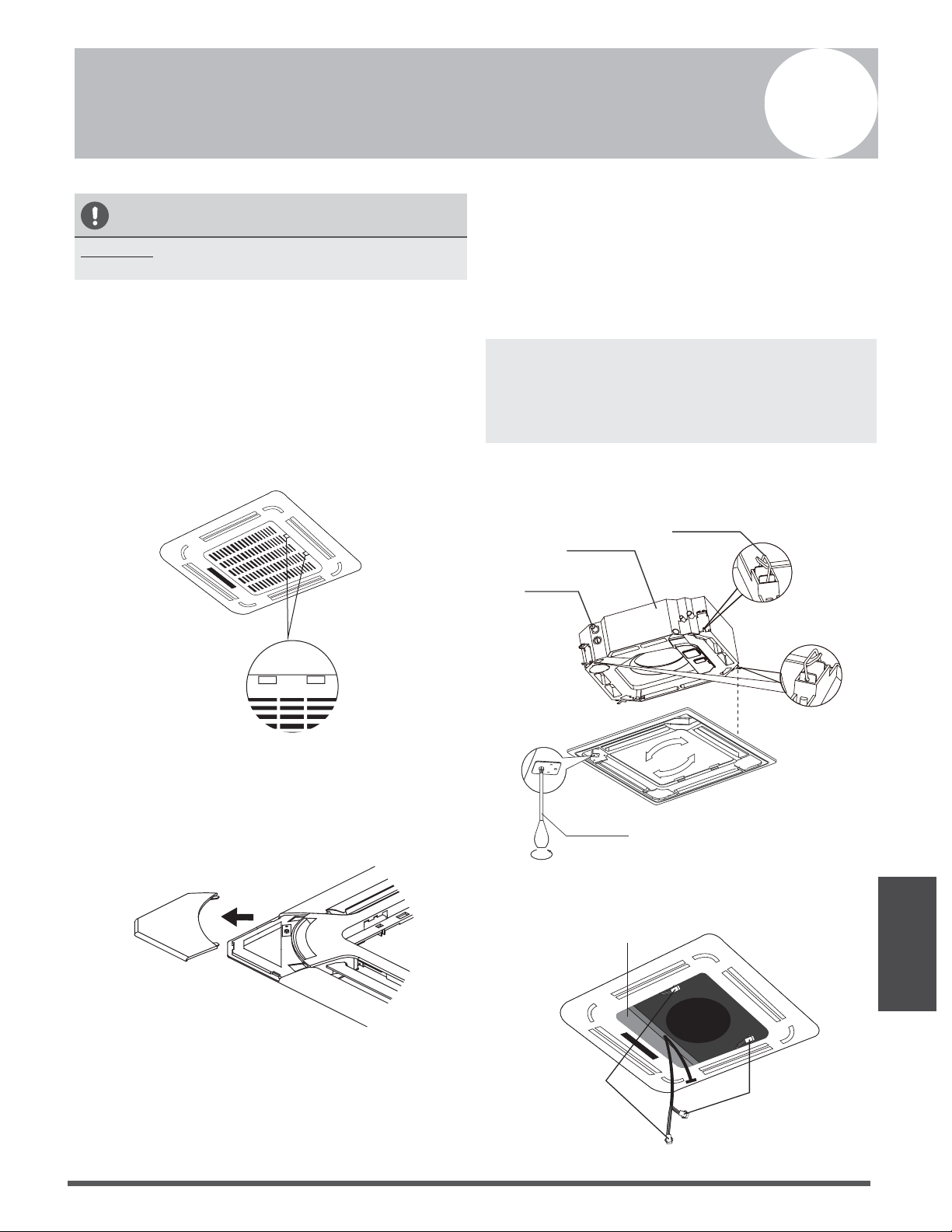
Step 1: Remove the front grille.
1. Push both of the tabs towards the middle
simultaneously to unlock the hook on the
grille.
2. Hold the grille at a 45° angle, lift it up
slightly and detach it from the main body.
Fig. 10.1
Step 2: Remove the installation covers at the
four corners by sliding them outwards.
Fig. 10.2
Step 3: Install the panel
Align the front panel to the main body, taking
into account the position of the piping and
drain sides. Hang the four latches of the
decorative panel to the hooks of the indoor
unit. Tighten the panel hook screws evenly at
the four corners. (See Fig 10.3)
NOTE: Tighten the screws until the thickness of
the sponge between the main body and the
panel reduces to 4-6mm (0.2-0.3”). The edge
of the panel should be in contact with the
ceiling well.
Adjust the panel by turning it to the arrowed
direction shown in Fig 10.3 so that the ceiling
opening is completely covered.
Piping side
Drain side
Latch
Screwdriver
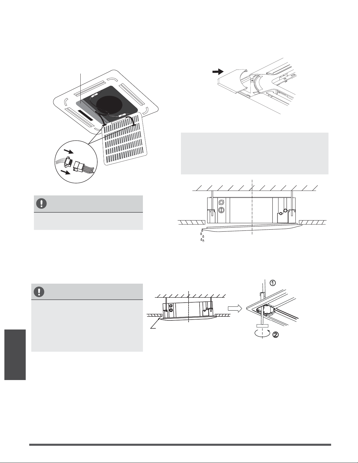
1.
Connect the two louver motor connectors
to the corresponding wires in the control
box.
Connect the
louver motor
Control box
Connect the
louver motor
Fig. 10.4
Fig. 10.3
Panel Installation
Panel Installation
10
Page 26
Panel Installation
2. Remove foam stops from inside the fan.
3.
Attach the side of the front grille to the
panel.
4.
Connect the display panel cable to the
corresponding wire on the main body.
Control box
Fig. 10.5
5.
Close the front grille.
6.
Fasten the installation covers at all four
corners by pushing them inwards.
(See Fig.10.6)
Fig. 10.6
NOTE: If the height of the indoor unit needs to
be adjusted, you can do so through the
openings at the panel’s four corners. Make sure
that the internal wiring and drainpipe are not
aected by this adjustment.
CAUTION
Failure to tighten screws can cause
water leakage.
Water condensation
CAUTION
If the unit is not hung correctly and
a gap exists, the unit’s height must
be adjusted to ensure proper
function. The unit’s height can be
adjusted by loosening the upper nut,
and adjusting the lower nut.
Loosen upper nut
Adjust lower nut
Gap not allowed
Fig. 10.8
Fig. 10.7
Page 27
Test Run
Before Test Run
A test run must be performed after the entire
system has been completely installed. Confirm
the following points before performing the test:
a)
The indoor and outdoor units are properly
installed.
b)
Piping and wiring are properly connected.
c)
Ensure that there are no obstacles near the
inlet and outlet of the unit that might cause
poor performance or product malfunction.
d)
The refrigeration system does not leak.
e) The drainage system is unimpeded and
draining to a safe location.
f) The heating insulation is properly installed.
g)
The grounding wires are properly connected.
h)
The length of the piping and the added
refrigerant stow capacity have been
recorded.
i)
The power voltage is the correct voltage
for the air conditioner.
CAUTION
Failure to perform the test run may result in unit
damage, property damage or personal injury.
Test Run Instructions
1.
Open both the liquid and gas stop valves.
2.
Turn on the main power switch and allow the
unit to warm up.
3.
Set the air conditioner to COOL mode.
4.
For the Indoor Unit
a. Ensure the remote control and its buttons
work properly.
b.
Ensure the louvers move properly and can
be changed using the remote control.
c.
Double check to see if the room
temperature is being registered correctly.
d.
Ensure the indicators on the remote
control and the display panel on the indoor
unit work properly.
e.
Ensure the manual buttons on the indoor
unit works properly.
f.
Check to see that the drainage system is
unimpeded and draining smoothly.
g. Ensure there is no vibration or abnormal
noise during operation.
5.
For the Outdoor Unit
a.
Check to see if the refrigeration system is
leaking.
b.
Make sure there is no vibration or
abnormal noise during operation.
c.
Ensure the wind, noise, and water
generated by the unit do not disturb your
neighbors or pose a safety hazard.
6. Drainage Test
a.
Ensure the drainpipe flows smoothly. New
buildings should perform this test before
finishing the ceiling.
b.
Remove the test cover. Add 2,000ml of
water to the tank through the attached
tube.
c.
Turn on the main power switch and run
the air conditioner in COOL mode.
d.
Listen to the sound of the drain pump to
see if it makes any unusual noises.
e.
Check to see that the water is discharged.
It may take up to one minute before the
unit begins to drain depending on the
drainpipe.
f.
Make sure that there are no leaks in any of
the piping.
g.
Stop the air conditioner. Turn o the main
power switch and reinstall the test cover.
NOTE: If the unit malfunctions or does not
operate according to your expectations, please
refer to the Troubleshooting section of the
Owner’s Manual before calling customer service.
Test Run
11

Page 28
The design and specications are subject to change without prior notice for product
improvement. Consult with the sales agency or manufacturer for details.
QSQ4I-026AEN
16122500000189
20160301
Parker Davis HVAC International, Inc.
2250 NW 102 Place, Doral, FL 33172
Phone: (800) 243-0340
www.highseer.com

Page 29

Page 30