
INSTALLATION AND OPERATION INSTRUCTIONS
For use under oating laminate, engineered wood, and oating tile ooring
CAUTIONS:
THIS EQUIPMENT SHALL BE INSTALLED ONLY BY QUALIFIED PERSONNEL WHO ARE FAMILIAR WITH
THE CONSTRUCTION AND OPERATION OF THE APPARATUS AND THE RISKS INVOLVED.
THE INSTALLATION OF THIS HEATING PRODUCT SHALL BE IN ACCORDANCE WITH THE MANUFACTURER’S INSTRUCTIONS AND LOCAL AND NATIONAL CODES.
IN CANADA,THE INSTALLATION SHALL BE MADE ACCORDING TO THE PROVISIONS OF SECTION 62 OF THE CANADIAN ELECTRICAL CODE, PART 1.
WARNING - AS DESCRIBED IN THESE INSTRUCTIONS, LEAD WIRES ARE NOT TO BE ROUTED OVER PADS OR COME INTO CONTACT WITH THE HEATING ELEMENTS AS
DAMAGE TO SUPPLY CONDUCTOR INSULATION MAY OCCUR IF CONDUCTORS ARE ROUTED TO CONTACT HEATING ELEMENTS. REFER TO INSTALLATION INSTRUCTIONS
FOR RECOMMENDED MEANS OF ROUTING SUPPLY CONDUCTORS.
THE TYPE AND THICKNESS OF FLOOR COVERING MATERIALS USED WITH THIS PRODUCT MUST NOT EXCEED A THERMAL INSULATION “R” VALUE OF 2.0.
CAUTION: USE COPPER ONLY AS SUPPLY CONDUCTORS. THERE ARE NO SPECIAL CRIMPING TOOLS REQUIRED FOR THIS PRODUCT.
Radiant Heat Film
for Floating Floors
Radiant Heat Film
for Floating Floors

Installation and Operation manual
2500 Old Hadar Road
Norfolk, NE 68702
888-379-9695 • FAX 402-379-9737
Copyright © 2020 MP Global, LLC
Radiant Heat Film
for Floating Floors
The Radiant Heat for Floating Floors system works just like the sun. When the thermostat calls for power, the
heating element warms the floating floor or laminate finished flooring surface by providing radiant heat, the same
type of heat that warms you on a cool spring day. Although the air is cool, the radiant heat from the sun keeps
you warm.
The radiant heat warms your floor, and provides clean even heat throughout the room by uniformly warming the
objects while providing thermal comfort. There is no need to directly over-heat the air. This is the opposite of how
a conventional forced hot air or baseboard heating systems works. In other types of heating systems, the large
mass of air in a home is heated while the objects and especially the outside walls remain relatively cool.
CAUTION:
Read and follow all the installation instructions in this manual before attempting
to install the Radiant Heat for Floating Floors. Improper installation procedures
or techniques can cause potentially unsafe conditions, including overheating and
shock hazards. Failure to comply with the instructions in this manual can void
the manufacturer’s warranty. Electrical connections should only be made by
licensed contractors.
NOTE:
Upon removing the heating mats from the box, it is important to check and record
the resistance of each mat using a digital ohmmeter, and compare those readings
with the baseline resistance indicated on the stickers attached to the mats. If
any mat shows a resistance reading that varies from the baseline value, call the
technical support hotline at 1-888-WARM PAD.
INSTALLATION AND OPERATION
Radiant Heat Film
for Floating Floors

25 YEAR LIMITED WARRANTY
MP GLOBAL PRODUCTS, LLC (THE “MANUFACTURER”) WARRANTS TO THE ORIGINAL PURCHASER (THE “OWNER”) THAT THIS
RADIANT HEAT FILM FOR USE UNDER FLOATING OR TILE FLOORS (THE “PRODUCT”) will be free of defects in workmanship
and materials and will conform in all material respects to any written specification that the Manufacturer provided to that
customer before the purchase.
If that customer believes that a shipment of product fails to satisfy the above warranty, that customer must (a) contact the
Manufacturer in writing within 25 years after that customer receives the shipment, including a detailed explanation of the
alleged nonconformity and (b) return the shipment to the Manufacturer postage prepaid. If The Manufacturer reasonably
determines through examination of the returned shipment that the shipment did not satisfy the above warranty, then AS
THE MANUFACTURER EXCLUSIVE LIABILITY AND THE CUSTOMER’S SOLE REMEDY, THE MANUFACTURER WILL, WITHIN A
REASONABLE PERIOD OF TIME, REPAIR THE PRODUCT, REPLACE THE PRODUCT WITH THE SAME OR SIMILAR PRODUCT, OR
CREDIT THE CUSTOMER’S ACCOUNT WITH THE PURCHASE PRICE, WHICHEVER THE MANUFACTURER MAY ELECT IN ITS SOLE
DISCRETION. If the Manufacturer determines that the function of the Product caused the failure of the overlying finished floor
covering, and installation instructions were properly followed during installation, the Manufacturer will repair or replace the
finished floor covering at no cost to the customer.
This warranty does not apply if the Manufacturer reasonably determines that the product has been cut improperly, added to or
otherwise altered, stored improperly, misused, damaged, or installed not in accordance with the instruction manual supplied
by the Manufacturer. The Manufacturer requires that this product be used ONLY with approved control devices. Use of any other
control device will render the provisions of this warranty null and void. This warranty covers only components manufactured
by the Manufacturer. Components such as attaching hardware, connecting parts, wire, tape, and other items included in kits
or assemblies that are not manufactured by the Manufacturer are excluded from the provisions of this warranty.
Except as expressly provided in this Limited Warranty, the customer is responsible for the cost of labor, service calls,
insurance, shipping, installation costs and any other expense or damage incurred.
THE FOREGOING WARRANTY IS IN LIEU OF ALL OTHER REPRESENTATIONS, WARRANTIES, OR CONDITIONS, EXPRESS OR
IMPLIED, INCLUDING WITHOUT LIMITATION ANY IMPLIED WARRANTY OF MERCHANTABILITY, FITNESS FOR A PARTICULAR
PURPOSE OR NON-INFRINGEMENT, AND OF ANY OTHER OBLIGATION OR LIABILITY ON THE PART OF THE MANUFACTURER
WHETHER BY STATUTE, CONTRACT, STRICT LIABILITY, TORT OR OTHERWISE.
THE MANUFACTURER IS NOT RESPONSIBLE FOR ANY INCIDENTAL, CONSEQUENTIAL, MULTIPLE, PUNITIVE OR INDIRECT
DAMAGES OR LOSS, LOSS OR DAMAGE TO OR LOSS OF USE OF FACILITIES OR OTHER PROPERTY, OR FOR LOST PROFITS
OR LOST REVENUE, WHETHER BASED UPON WARRANTY, STATUTE, CONTRACT, STRICT LIABILITY, TORT OR OTHERWISE. THE
MANUFACTURER SHALL IN NO EVENT BE LIABLE FOR THE PERFORMANCE OF, OR COST OF PERFORMING, THE REMOVAL OR
INSTALLATION OF THE PRODUCT OR ANY PRODUCT OR MATERIAL INTO WHICH IT IS INSTALLED, INCORPORATED OR ADDED.
THE CUSTOMER IS RESPONSIBLE FOR THE COST OF LABOR, SERVICE CALLS, INSURANCE, SHIPPING, INSTALLATION COSTS
AND ANY OTHER EXPENSE OR DAMAGE INCURRED.
IN NO EVENT SHALL THE MANUFACTURER’s MAXIMUM LIABILITY EXCEED THE PURCHASE PRICE FOR THE RELEVANT
SHIPMENT OF PRODUCT, EXCEPT TO THE EXTENT MADE MANDATORY BY LAW.

TABLE OF CONTENTS
Safety Information ............................................................................................................................... iii
Section 1. Introduction ........................................................................................................................ 1
How To Use This Manual ................................................................................................................ ......... ...1
Features ............................................................................................................................................. ....... 1
For Additional Help ........................................................................................................................... ......... .1
Before You Begin .............................................................................................................................. ..........1
NEVER Do the Following: .................................................................................................................. ......... .2
ALWAYS Do the Following: ............................................................................................................... .......... .2
Section 2. Designing the Installation ............................................. ............... .................................3
Sketch the System Layout .............................................................................. ......... ...................................3
Control Devices ..........................................................................................................................................4
Thermostat Requirements ................................................................................. ......... ................................4
Locating the Thermostat .................................................................................... ......... ...............................4
Floor Construction .............................................................................................. ......... ...............................4
Design Clearances ................................................................................................ ........ .............................4
Section 3. Installation .................................................................................. .......... .............................5
Preparing the Job Site ................................................................................................ ......... .......................5
What You Will Need ............................................................................................................ ......... ...............5
3.2 Electrical Installation ............................................................................................................. ...... ........6
Step 1. GFCI Installation ...................................................................................................... ......................6
Step 2. Multiple Mat Installations ........................................................................................ ......... .............6
Step 3. Install Electrical Boxes ..................................................................................................... ..............6
Step 4. Bottom Plate Work................................................................................................... ......................6
Step 5. Install Power Lead Conduit ....................................................................................... ......... ............6
3.3 Installing the Units ............................................................................................................ ...... .............8
Installation Sequence ............................................................................................................... ..................8
Step 1. Inspect and Test Mats .................................................................................................. .................8
Step 2. Install Lower Vapor Barrier ............................................................................................ ......... ........8
Step 3. Install Underlayment ................................................................................................... ...................8
Step 4. Install Thermostat Sensor .......................................................................................... .....................9
Step 5. Prepare Mats ........................................................................................................... ......................9
Step 5a. 2-in-1 Radiant Film Mat Preparations....................................................................................... .... .9
Step 6. Install Mats .............................................................................................................. ....................10
Step 7. Recheck Mat Resistance ............................................................................................ ........ ..........10
Step 8. Connect the Electrical Leads ...................................................................................... .................10
Installation & Owner’s Guide i
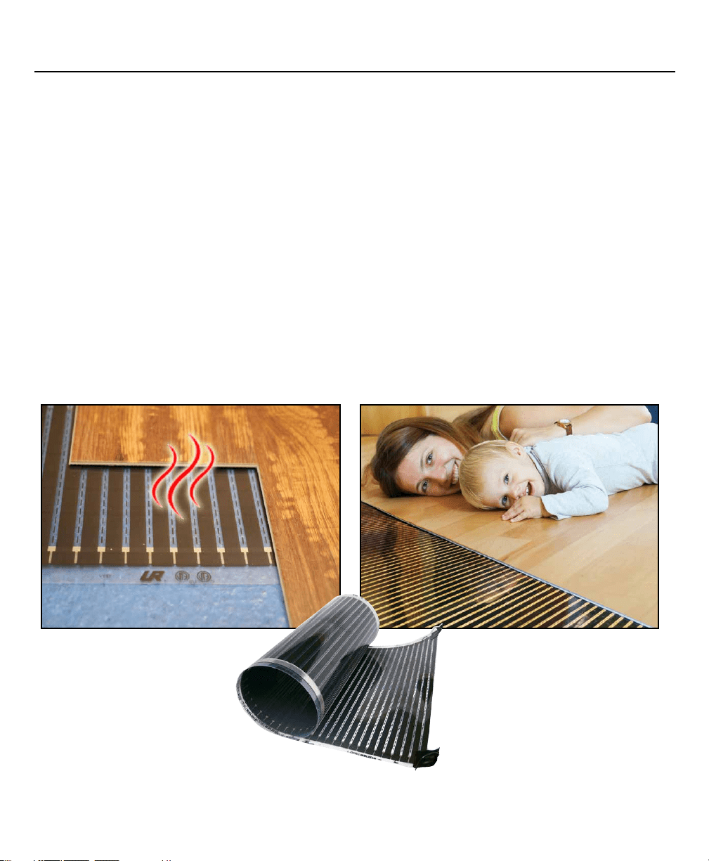
TABLE OF CONTENTS (continued)
Section 4. Inspection and Testing ........................................................................... .....................11
Visual Inspection ........................................................................................................... ......... ..................11
Electrical Test ..................................................................................................................... ......................11
Ohms resistance chart .............................................................................................................................. 13
Documentation .................................................................................................................. ......................14
Test for Heating.................................................................................................................. .......................15
Troubleshooting ................................................................................................................ .......................15
Complete the Installation ................................................................................................... ..... ................16
Place Warning Labels ........................................................................................................ .......................16
Section 5. Operation ....................................................................................................... ......... ..........17
Operating the System ....................................................................................................... .......................17
Precautions ........................................................................................................................ ........ ..............17
Never pierce the floor ...............................................................................................................................17
Repair/Remodel information .....................................................................................................................18
Installation & Owner’s Guide ii
CAUTION:
Make sure that the jobsite is neat and clean before working with the mats. Nails,
screws, and other sharp debris can damage the mats creating a potential shock
hazard. Any mats which become torn or otherwise damaged must be discarded.
Ensure that the breaker supplying power to the heating mats has been turned
off before making electrical connections.
When installing any other materials on or near
a heated floor, ensure that no heating mats are
punctured by nails, screws, etc.
Not for use in wet areas, such as showers. This
system is only for use in areas considered dry
locations by National Electrical Code.
Do not install mats in walls, under walls or partitions,
or in locations where they will be covered by floor
hugging furniture or fixtures.
CAUTION:
Flooring materials must be rated for use
with electric floor warming system.
Do not fold or alter the heating mats.
Do not place futons, beanbag chairs, or
similar furniture on heated floors.
Throughout the manual you will see Cautions and Notes. These notices highlight conditions, procedures, or other
information that require special attention to prevent damage to the mats, to your flooring, or possible injury.
For a safe and functional installation of Radiant Heat for Floating Floors, read and follow these important safety
precautions. Failure to comply with these items may result in injury or damage to the mats.
This information must be read and understood by all technicians who will be working in the area of an installed
Radiant Heat for Floating Floors or main electrical systems. Failure to follow these guidelines may result in a risk
of electric shock or fire hazard.
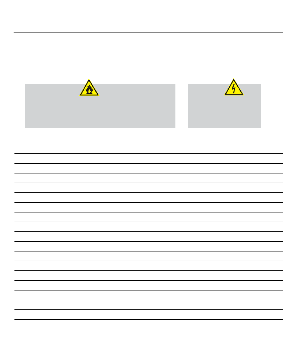
Indicates precautions or procedures that should be followed
to prevent the possibility of fire.
Indicates precautions or procedures that should be followed
to prevent the possibility of electrical shock.
Indicates an item that you should pay special attention to. For
example, notes are used to highlight installation tips.
SAFETY INFORMATION
Installation & Owner’s Guide iii
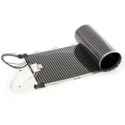
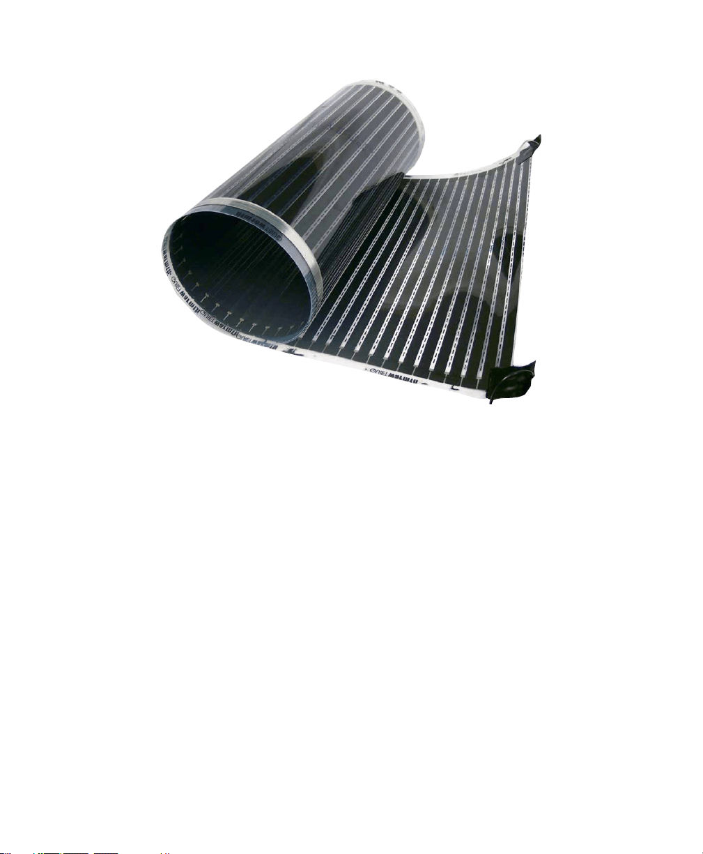
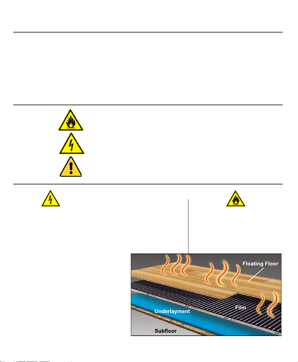
Radiant Heat Film for Floating Floors is a unique heating system that is installed below floating flooring materials
to create warm, comfortable floors and provide supplementary or primary heat. Radiant Heat Film consists
of low heat density film heating mat sets that cover the majority of the open floor area to ensure optimum
thermal comfort. Radiant Heat Film comes as standard kits which may be modified and cut to shorter lengths in
accordance with instructions or is available as custom orders. Warranted to be free of defects in manufacture for
a period of 25 years.
The Radiant Heat Film
System can be installed on any standard sub-floor, so long as it is flat, smooth, and free
from protrusions such a nails, screws, etc. When specifying as primary heat, a heat loss calculation must be
performed to determine how many watts are required to heat the room or space.
For more information go to www.RadiantHeatFilm.com
SECTION 1. Introduction
Installation & Owner’s Guide 1
Features:
This manual is organized into five sections:
• Introduction • Designing the Installation
• Installation • Inspection and Testing • Operation
• Radiant Heat Film must be installed on a dedicated 20
amp circuit. Do not connect lights, outlets, or any other
electrical device to any branch circuit used with the
Radiant Heat Film Floating Floor Heat mats.
• All wiring, fuses and/or circuit breakers must conform to
National Electrical Code requirements.
• Technical Hotline: 1-888-379-9695
• Website: www.RadiantHeatFilm.com
• Email: [email protected]
How to Use This Manual
Before You Begin
For Additional Help
• 12 watts per square foot
• 0.016” thick, Easy to install
• Available in 18” and 36” widths in
standard kit lengths or custom lengths
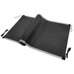
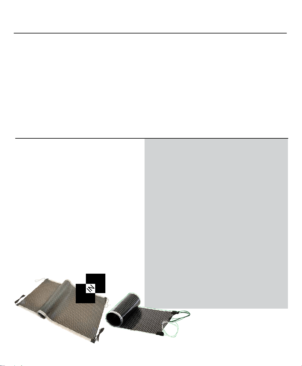
• 2-in-1 Kits are available in 18” and 36” widths
and feature factory attached leads on both ends
of mat. Designed to be cut apart to desired
lengths for less waste and versatile coverage.
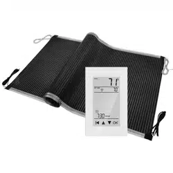
• 120V or 240V
• Thermostat controlled
• Warranted to be free of defects in
manufacture for a period of 25 years
2
1
1. Introduction Continued
Installation & Owner’s Guide 2
NEVER Do the Following: ALWAYS Do the Following:
• Install in wet areas such as showers. This system is only
for use in areas considered dry locations by National
Electrical Code.
• Never fold or alter the heating mats.
• Never install mats under walls or partitions, or in locations
where they will be covered by floor hugging furniture or
fixtures. Call for instruction before proceeding.
• Never place futons, beanbag chairs, or similar furniture
on heated floors.
• Never install in walls.
Protect the circuit supplying power to the
Radiant Heat for Floating Floors mats with a
ground fault circuit interrupter (GFCI).
SECTION 2. Designing the Installation
Radiant Heat for Floating Floors is made up of four major components: the heating mats, the wiring, the control
device and the floor structure. These components work together to create a system that provides comfortable,
trouble free floor warming or as primary heat when appropriately specified. Designing a Radiant Heat Film system
is straightforward. The following instructions will ensure a trouble-free design and full compliance with the war-
ranty requirements.
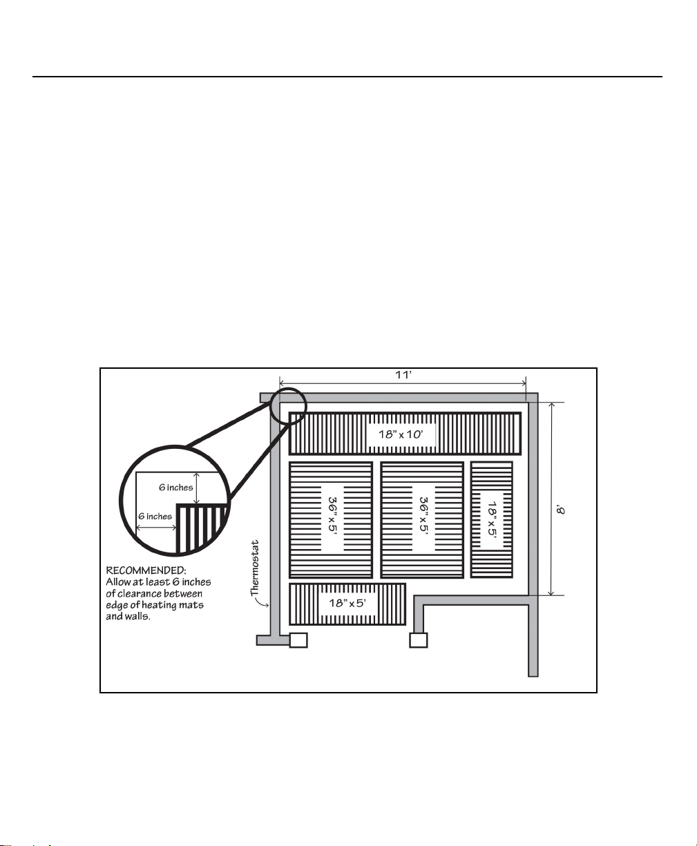
Sketch the System Layout
A sketch of the area to be warmed, including the mat locations and associated wiring is suggested to make instal-
lation and ordering as smooth as possible. Use the sketch below as an example. Allow at least 6 inches clearance
between the edge of the mats and the wall. Note that the thermostat is located on an interior wall where it will
not be subjected to direct sunlight and that the length of the non-heating leads is taken into account. Ensure that
non-heating leads will not cross over any heating mats.
Installation & Owner’s Guide 3

2. Designing the Installation Continued
Installation & Owner’s Guide 4
All heated areas must be protected by a GFCI in either the thermostat or at the service panel. The fuse or circuit
breaker used to protect the circuit supplying power to the Radiant Heat Film system must be rated for a maximum
of 20 amperes (no greater than 16 amp load). If a lower rated fuse or circuit breaker is used, it must be rated
at least 25% greater than the heating system load attached to it. If an area requires more than the 16 amperes
allowed, additional branch circuits may be used, each having its own overcurrent protection. These branch circuits
may all be controlled by a single thermostat if it is used with a system of electric relays or power modules.
Locating the Thermostat
Thermostats are usually located near the power leads. However, they can be located almost anywhere, because
the power leads and the sensor wire can be routed to electrical junction boxes and extended to a location outside
the heated room (such as a utility room or basement). Location of the thermostat should be approximately 60”
(152 cm) above the floor on an inside wall, near the center of the room to allow the connection leads to reach. A
3” deep box is recommended for the thermostat.
Floor Construction
Radiant Heat for Floating Floors can be installed on any standard sub-floor, so long as it is flat, smooth,and free
from protrusions such a nails, screws, etc.
Design Clearances
When designing the heating system, care must be taken to ensure that proper clearance is maintained
from fixtures which may be part of the floor.
• For best results, there should be a 6 inch (15 cm) clearance between the edge of the mats and the perimeter of
the room or the walls. Clearance may be greater than 6 inches.
• Decorative trim: Mats must be installed so that they will not be covered, even in part, by decorative trim,
baseboards or other structures on the floor. Heating mats which are covered by other structures may overheat.
• Wiring: Electrical wiring in the floor, other than that for the heating system, must be at least 2 inches (5 cm)
away from the heating mats and/or separated from the heating mats by insulation or the building structure.
• Heat Sources: At least 8 inches (20 cm) of clearance must be maintained between heat sources and the Radiant
Heat Film mats. Heat sources include hot water pipes, stoves,fireplaces, wood stoves, hot air vents, etc.
The installation of this heating product and
listed components shall be in accordance with
Article 424, of the National Electric Code, ANSI/
NFPA 70. All electrical connections should be
made by a licensed electrician.
The system must be installed using a thermostat
approved by the manufacturer. Use of any
other thermostat will void the manufacturer’s
warranty. For a list of approved thermostat
devices, refer to www Radiant Heat Film. com.
NOTES:
SECTION 3. Installation
Installation & Owner’s Guide 5
NOTES:
The installation of this heating product shall be in accordance with the manufacturer’s instructions. Improper
installation can result in mats that do not work, poor heating, and can void the manufacturer’s warranty.
Heating mats should not be installed at or below 32°F (0°C).
This equipment shall be installed only by qualified personnel who are familiar with the construction and operation
of the apparatus and the risks involved.
The installation of this product shall be in accordance with Article 424, of the National Electrical Code, ANSI/NFPA
70. ETL listed to UL499.
Note that installations over non-insulated concrete subfloors may require a longer period of time to adjust to your
desired temperature.
Preparing the Job Site
Make sure that the job site is neat and clean before working with the Radiant Heat for Floating Floors.
Nails, screws, and other sharp debris can damage the mats. Any mats which become torn or otherwise
damaged must be discarded.
What You Will Need
• Radiant Heat Film mats
• Kapton Discs and Warning Labels (included in kits)
• Thermostat: A recommended floor-sensing
thermostat (go to www.Radiant Heat Film.com for
recommended thermostats)
• GFCI Breaker (if not part of the thermostat)
• Junction Boxes: Minimum of two required for each
room or area. One box (3”) required for thermostat,
one box (4”) required for electrical connections
• Vapor Barrier (6 mil) (only for concrete slabs
when using underlayment without an attached
vapor barrier)
• Underlayment
• Duct tape
• Tools: Digital Ohm Meter (multi-meter), wire
stripper, screw driver, wood chisel, knife and
scissors to cut underlayment
• 12/2 Romex Wire

3. Installation Continued
Installation & Owner’s Guide 6
Electrical Installation
Step 1. GFCI Installation
Radiant Heat Film Radiant Heat for Floating Floor mats must be protected by a ground fault circuit interrupter
(GFCI). This can be done either by the internal GFCI in the thermostat (as long as it directly controls the mat), or
by a GFCI protected circuit breaker. Follow all local building and electrical codes. Typical Amperage Requirement:
120 VAC Radiant Heat Film
0.1 amps per square foot, or 10 amps per 100 square foot of mat.
Step 2. Install Additional Power Modules
Depending on the amperage requirements of the mat(s), one or more secondary power modules may be required.
Do not load the thermostat control with more than 15 amps. The National Electrical Code specifies that each
branch circuit used in conjunction with a heating system must be for the exclusive use of the heating system. Do
not connect lights, outlets, etc. to any branch circuit used with the Radiant Heat Film system.
Step 3. Install Electrical Boxes
Install Junction box for the control device (thermostat) according to the manufacturer’s instructions. This box
should be located, unobstructed, on an inside wall so that the device reads accurately.
Install a 4x4 inch junction box for making electrical connections between the mats and thermostat.
Step 4. Bottom Plate Work
Drill or saw holes at the bottom plate. One hole is for routing power leads or conduit and the other is for the
thermostat sensor. These holes should be directly below the electrical box(es). It is recommended that you drill or
saw holes at the bottom plate. You may also use a notch technique as an alternative.
Step 5. Install Power Lead Conduit
Route the power leads from the thermostat down the wall cavity through opening in the bottom of plate to
connect the mats.
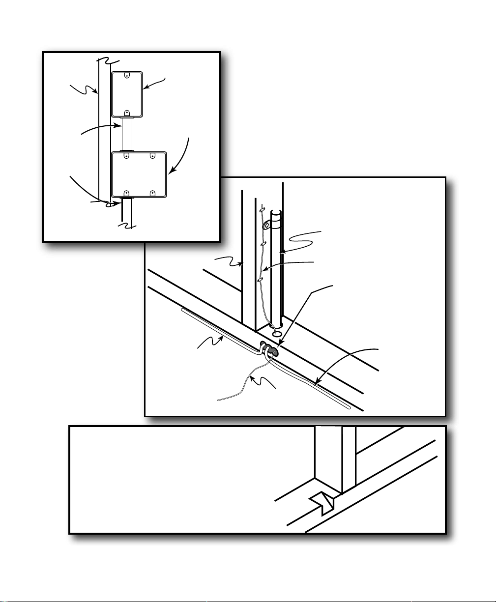
Alternatively, you can use
the notch method. Cut/chisel
a notch in the bottom plate
to allow clearance for Lead and
Sensor Wires.
Lead Wire
Conduit
Sensor Wire
Thermostat
Junction
Box
Connection
Junction
Box
Wall Stud
Wall Stud
Romex
12/2
Conduit
To Bottom Plate
Leads From
Elements
Leads From
Elements
Sensor
Wire
NOTE: Drill into Base Plate
as needed to allow Lead
and Sensor Wires to be
run to Thermostat
3. Installation Continued
Installation & Owner’s Guide 7
3. Installation Continued
Installation & Owner’s Guide 8
3.3 Installing the Units
Installation Sequence
The sequence of installation should be as follows:
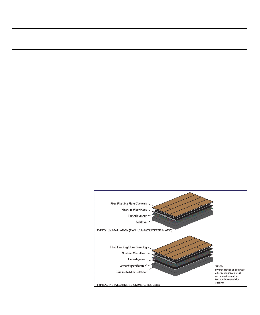
1. Apply lower vapor barrier if installing over concrete slab using underlayment without a built-in vapor barrier.
2. Install insulating underlayment.
3. Install heating mats.
4. Install finished floor covering.
Step 1. Inspect and Test Mats
1. Visually inspect each mat for any signs of damage that may have occurred during shipping.
2. The individual mats provided with each kit have resistance readings (in ohms) on a sticker on the mat. Using
an ohm meter, check and verify the resistance of each mat. If any reading is significantly different from the value
on the mat, contact the technical hotline at 1-888 WARM PAD.
Step 2. Install Lower Vapor Barrier
For installations on concrete slabs, or at below grade, ensure the lower 6 mil (0.15 mm) vapor barrier is com-
pletely and properly installed.
Step 3. Install Underlayment
For all floors, install a suitable underlayment over the subfloor and over any vapor barriers that needed installed
over concrete or at below grade. Some underlayments provide a suitable pre-attached vapor barrier built into
the underlayment. Refer to all floor-
ing manufacturer’s underlayment
recommendations.
For under floating tile systems, no
underlayment is needed. For instal-
lations over concrete slabs in cold
regions, it is highly recommended
that an insulating underlayment be
installed over the entire floor. Follow
all installation instructions of the un-
derlayment manufacturer. The Radi-
ant Heat Film film mat(s) then install
directly on top of the underlayment
layers.
3. Installing the Units Continued
Installation & Owner’s Guide 9
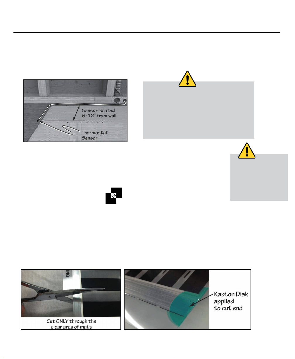
Step 4. Install Thermostat Sensor
Cut an area of underlayment to push the sensor down so it is completely level with the mat. Tape the
floor sensor to the underlayment in an area at least 1 inches (2.5 cm) from any heated (black stripe) of the
heating mat. Do not allow sensor to contact mat.
Step 5. Prepare Mats
If installing cut-to-length mats, you first need to prepare them for use, as follows:
1. Using the diagram you made earlier, cut the heating element to length using scissors.
2. Do not cut the end with wired connections; only cut the opposite end (without wiring).
3. Insulate the cut ends with Kapton Disks.
Step 5a. Radiant Heat Mats
Since the boxed kit for the 2-in-1 mat is designed to create 2 mats, both ends of the kit length have factory
installed lead wires. The end result is it will create 2 mats out of 1 boxed length. The mat MUST be cut into 2
desired lengths in order to operate correctly. Similar as in step 5 you will need to properly prepare the 2-in1
as follows:
1. Using the diagram you made earlier, cut the heating element into 2 desired to lengths using a scissors.
Ensure not to cut into black stripe and stay only on the dotted line when cutting to lengths.
2. Insulate the 2 created mat cut ends with the supplied Kapton Disks on the exposed bus bars.
There will be 4 bus bars to cover after the cut.
Sensor is thicker than the heating mat. If
necessary, saw a groove in the underlayment
between the mats, to recess the sensor to
the level of the mat. Use duct tape to secure
the sensor in the groove. Do not damage the
sensor. Ensure the sensor is set down so it is
level with the mat and not on top of the mat.
NOTE:
Cut only through the clear
area between the heating
stripes. NEVER cut closer
than ¼ inch (6 mm) to the
heating stripes and DO
NOT cut into the heating
stripes themselves.
NOTE:
2
1
3. Installing the Units Continued
Installation & Owner’s Guide 10
Step 6. Install Mats
1. Clear the floor of all debris, nails, etc. so the floor is smooth, clean and dry.
2. Roll out the mats over the floor surface according to the layout created in Section 1, Designing the Installation.
3. Cut out an area of the underlayment and push the connectors down so they are completely level with the
mat. Route the cold leads between sections of the underlayment. If necessary, cut a narrow channel in the
underlayment to route the cold leads.
4. Attach the heating mats to the underlayment using a high quality duct tape.
Step 7. Recheck Mat Resistance
Using an ohm meter, recheck the resistance of each mat. If any reading has changed, closely inspect the mat for
damage. For additional help contact the technical hotlilne at 1-888 WARM PAD.
Step 8. Connect the Electrical Leads
Now, depending upon your wire lead installation, run the lead
wires from the individual mat(s) along the base of the wall and up
to the junction box. Wire the heating mats to the control according
to the manufacturer’s instructions using the 12/2 Romex wire.
Follow all national and local electric codes for final electrical hook
up. Refer to the complete thermostat installation guide. On 120V
systems 150 sqft of radiant heat film mats can be wired together
for one thermostat to run. On 240V systems 300 sq ft of radiant
heat film mats can be wired for one thermostat to run. If additional area coverage is needed, a power module
may be added. Each circuit running the radiant heat system must be placed on a dedicated 20 amp circuit from
the main electrical box. Follow all installations of the thermostat’s installation instructions.
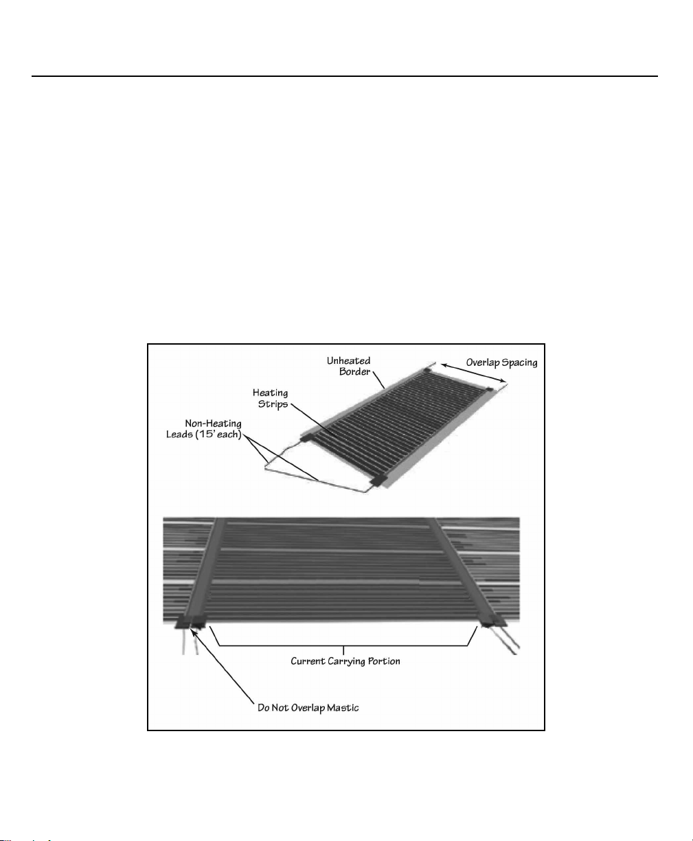
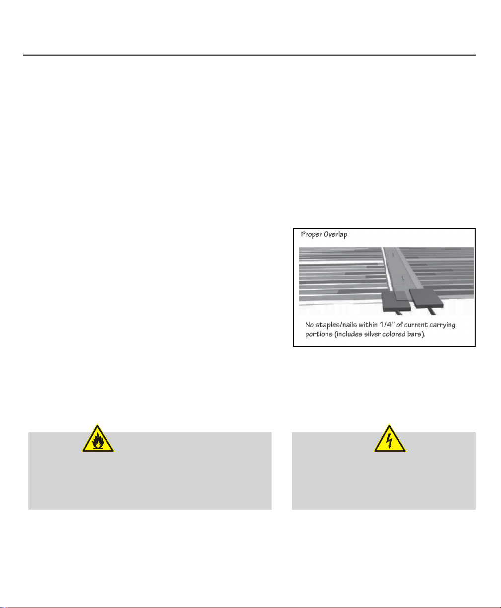
CAUTION:
Elements may be overlapped ONLY as shown in the figure below.
Under no circumstances may current carrying portions of the mats
overlap.Overlapping warming sections can result in overheating
and potential fire danger. When overlapped properly, the mats will
be spaced by their nominal width (18 inches or 36 inches).
CAUTION:
Take care not to damage the heating mats
while they are on the floor. Do not drop items
on mats and avoid unnecessary walking in
heating areas before finished flooring has
been applied.

SECTION 4. Inspection and Testing
Installation & Owner’s Guide 11
A visual and electrical check must be performed on the heating mats prior to activation. The heating test may
berequired by the laminate manufacturer based on the type of sub-floor being used (i.e. concrete). Always check
with your laminate manufacturer for any restrictions and/or requirements that they have concerning the use of
their product in conjunction with floor warming systems.
Visual Inspection
Also perform a visual check to look for any signs of damage to the mat or electrical leads that may have occurred
during installation. When visually checking the mats, look for any signs of damage, wear, or scratching that might
have occurred during installation. If any portion of a mat appears damaged, replace the entire mat. If damage is
found, call 1-888 WARM PAD for advice and/or replacement assistance.
Electrical Test
A resistance check across the supply leads of each mat using a digital ohm meter must be made to detect any
short or open circuits. Please refer to the charts on page 12 under the section of low resistance limits and high
resistance limits.
If the resistance check is between the low and high resistance limits shown on page 12, the system is connected
properly and no further testing is required. If the resistance is LOWER than the indicated low resistance limits on
page 12, contact 1-888-WARM PAD.
If the resistance is HIGHER than the indicated high resistance limits on page 12, this indicates a damaged mat.
Inspect all wiring for damage or loose connections and retest. If the resistance reading is ZERO, this indicates a
short circuit. Check the path that the wiring is taking and make sure that no wires are pierced or otherwise dam-
aged. Mats with damaged non heating leads must be replaced.
If the element or film has been cut to shorten the length, to calculate the new resistance, follow the
instructions below:
• 18 inch wide film - Each heating bar or stripe =0.86 Watts. Multiply the number of heating bars or stripes of
the newly shortened mat by 0.86 and this will equal the total wattage of the mat.
• 36 inch wide film - Each heating bar or stripe =1.75 Watts. Multiply the number of heating bars or stripes of
the newly shortened mat by 1.75 and this will equal the total wattage of the mat.

4. Inspection and Testing Continued
Installation & Owner’s Guide 12
120V Radiant Heat Film Resistance Values
Tolerances for resistance measurements are -5% and +10%. To determine nominal resistance for 120V, divide
14,400 by the total wattage. This will equal Nominal Resistance for the 120V material. Next, multiply nominalre-
sistance by 1.1 to equal the high limit. Then, multiply the nominal resistance by .95 to equal the low limit.
240V Radiant Heat Film Resistance Values
Tolerances for resistance measurements are -5% and +10%. To determine nominal resistance for 240V, divide
57,600 by the total wattage. This will equal Nominal Resistance for the 240V material. Next, multiply nominal
resistance by 1.1 to equal the high limit.Then, multiply the nominal resistance by .95 to equal the low limit.
NOTES:
Record the resistance measurements of each mat after installation. These measurements should be
compared to the readings recorded on the product label for each mat to confirm a successful installation.
These measurements are required for warranty registration.
If a mat fails the resistance check, it must be retested after any corrective actions.

Installation & Owner’s Guide 13
120V
Size Amps Watts Low Limit Nominal High Limit
1.5x1 0.15 18 760.00 800.00 880.00
1.5x2 0.3 36 380.00 400.00 440.00
1.5x3 0.45 54 253.33 266.67 293.33
1.5x4 0.6 72 190.00 200.00 220.00
1.5x5 0.75 90 152.00 160.00 176.00
1.5x6 0.9 108 126.67 133.33 146.67
1.5x7 1.05 126 108.57 114.29 125.71
1.5x8 1.2 144 95.00 100.00 110.00
1.5x9 1.35 162 84.44 88.89 97.78
1.5x10 1.5 180 76.00 80.00 88.00
1.5x11 1.65 198 69.09 72.73 80.00
1.5x12 1.8 216 63.33 66.67 73.33
1.5x13 1.95 234 58.46 61.54 67.69
1.5x14 2.1 252 54.29 57.14 62.86
1.5x15 2.25 270 50.67 53.33 58.67
1.5x16 2.4 288 47.50 50.00 55.00
1.5x17 2.55 306 44.71 47.06 51.76
1.5x18 2.7 324 42.22 44.44 48.89
1.5x19 2.85 342 40.00 42.11 46.32
1.5x20 3 360 38.00 40.00 44.00
3x1 0.3 36 380.00 400.00 440.00
3x2 0.6 72 190.00 200.00 220.00
3x3 0.9 108 126.67 133.33 146.67
3x4 1.2 144 95.00 100.00 110.00
3x5 1.5 180 76.00 80.00 88.00
3x6 1.8 216 63.33 66.67 73.33
3x7 2.1 252 54.29 57.14 62.86
3x8 2.4 288 47.50 50.00 55.00
3x9 2.7 324 42.22 44.44 48.89
3x10 3 360 38.00 40.00 44.00
3x11 3.3 396 34.55 36.36 40.00
3x12 3.6 432 31.67 33.33 36.67
3x13 3.9 468 29.23 30.77 33.85
3x14 4.2 504 27.14 28.57 31.43
3x15 4.5 540 25.33 26.67 29.33
3x16 4.8 576 23.75 25.00 27.50
3x17 5.1 612 22.35 23.53 25.88
3x18 5.4 648 21.11 22.22 24.44
3x19 5.7 684 20.00 21.05 23.16
3x20 6 720 19.00 20.00 22.00
3x21 6.3 756 18.10 19.05 20.95
3x22 6.6 792 17.27 18.18 20.00
3x23 6.9 828 16.52 17.39 19.13
3x24 7.2 864 15.83 16.67 18.33
3x25 7.5 900 15.20 16.00 17.60
240V
Size Amps Watts Low Limit Nominal High Limit
1.5x1 0.075 18 3040.00 3200.00 3520.00
1.5x2 0.15 36 1520.00 1600.00 1760.00
1.5x3 0.225 54 1013.33 1066.67 1173.33
1.5x4 0.3 72 760.00 800.00 880.00
1.5x5 0.375 90 608.00 640.00 704.00
1.5x6 0.45 108 506.67 533.33 586.67
1.5x7 0.525 126 434.29 457.14 502.86
1.5x8 0.6 144 380.00 400.00 440.00
1.5x9 0.675 162 337.78 355.56 391.11
1.5x10 0.75 180 304.00 320.00 352.00
1.5x11 0.825 198 276.36 290.91 320.00
1.5x12 0.9 216 253.33 266.67 293.33
1.5x13 0.975 234 233.85 246.15 270.77
1.5x14 1.05 252 217.14 228.57 251.43
1.5x15 1.125 270 202.67 213.33 234.67
1.5x16 1.2 288 190.00 200.00 220.00
1.5x17 1.275 306 178.82 188.24 207.06
1.5x18 1.35 324 168.89 177.78 195.56
1.5x19 1.425 342 160.00 168.42 185.26
1.5x20 1.5 360 152.00 160.00 176.00
3x1 0.15 36 1520.00 1600.00 1760.00
3x2 0.3 72 760.00 800.00 880.00
3x3 0.45 108 506.67 533.33 586.67
3x4 0.6 144 380.00 400.00 440.00
3x5 0.75 180 304.00 320.00 352.00
3x6 0.9 216 253.33 266.67 293.33
3x7 1.05 252 217.14 228.57 251.43
3x8 1.2 288 190.00 200.00 220.00
3x9 1.35 324 168.89 177.78 195.56
3x10 1.5 360 152.00 160.00 176.00
3x11 1.65 396 138.18 145.45 160.00
3x12 1.8 432 126.67 133.33 146.67
3x13 1.95 468 116.92 123.08 135.38
3x14 2.1 504 108.57 114.29 125.71
3x15 2.25 540 101.33 106.67 117.33
3x16 2.4 576 95.00 100.00 110.00
3x17 2.55 612 89.41 94.12 103.53
3x18 2.7 648 84.44 88.89 97.78
3x19 2.85 684 80.00 84.21 92.63
3x20 3 720 76.00 80.00 88.00
3x21 3.15 756 72.38 76.19 83.81
3x22 3.3 792 69.09 72.73 80.00
3x23 3.45 828 66.09 69.57 76.52
3x24 3.6 864 63.33 66.67 73.33
3x25 3.75 900 60.80 64.00 70.40
Resistance (Ohms) Resistance (Ohms)
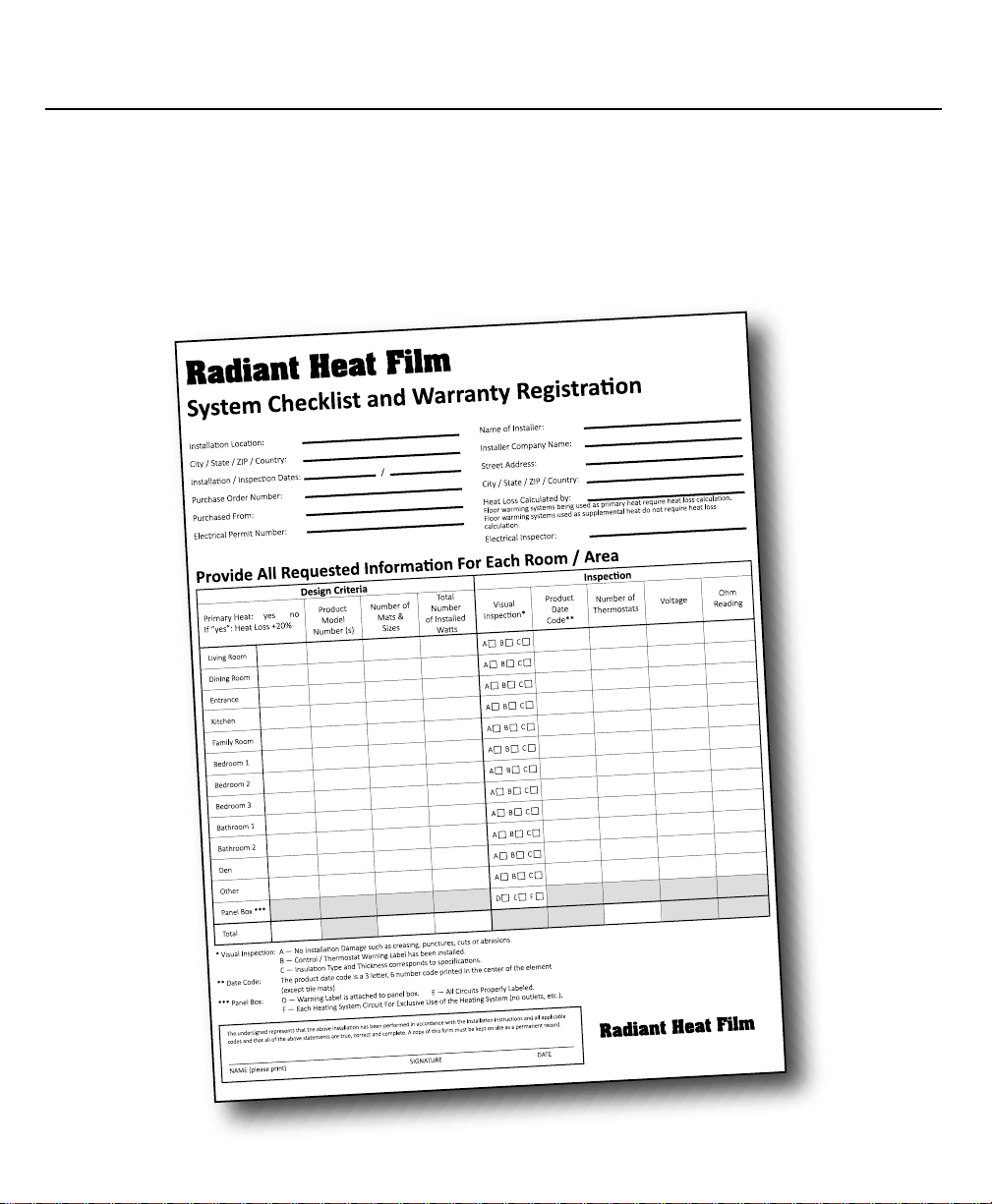
Documentation
The System Checklist and Warranty Registration form records vital information about your Radiant Heat Film
installation. Fill out all requested information on BOTH copies. One copy is returned to the manufacturer to register
the installation, and the second copy is for the homeowner’s records.
This manual must be attached to the service panel so that it is easily accessible to the homeowner and
any repair technicians.
4. Inspection and Testing Continued
Installation & Owner’s Guide 14
Test for Heating
1. Turn on the breaker and adjust the
thermostat so that the system begins
heating.
2. After the system has been on for several
minutes, run your hand over the heating
mats to ensure that they are warm.
3. If the mats do not become warm, double
check all wiring and re-perform the
electrical tests above (after turning off
power at the breaker).
Troubleshooting
It is important that this manual be followed during the
installation procedures and that all warnings be followed.
Wiring should be performed by a licensed electrician in
accordance with all applicable building and electrical codes
during the installation as well as for any trouble shooting of
the system. Failure to do so voids warranty.
A test of the system to make sure all mats are heating properly
is recommended prior to installation of finished flooring. The
manufacturer will not be responsible for the replacement
of the floor heating system if the system operation was not
checked and verified prior to installation of the flooring.
4. Inspection and Testing Continued
Installation & Owner’s Guide 15
Individual Mat
Not Warming
Verify that all leads from all mats are connected together to power source. Areas within a mat
that are not heating could be the result of damage and will require the mat to be replaced.
Slow to Heat Installations on concrete slabs can require a period of several days to warm up to desired temperature
especially if the slab is uninsulated in a cold climate. Set Thermostat to maximum heat to allow system
to continue running until it becomes warm. Then adjust thermostat down if needed. Verify floor tempera-
ture sensor is not directly on top of heating element causing the thermostat to shut off more frequently.
System Too Hot Adjust thermostat
Verify that correct voltage is being applied to heating elements rated for 120V Service.
Verify that thermostat has not been bypassed.
If necessary, reposition floor temperature sensor.
Thermostat GFCI If the thermostat trips and will not re-set, check the following:
System MUST be on a dedicated branch circuit separate from any other electrical devices which
could overload the circuit or create interference issues resulting in the GFCI to trip.
Check electrical connections to verify leads from all mats are wired in parallel (black to black / white
to white / red to red) and all connections are tight and properly insulated against grounding.
Check leads from mats to verify no nicks or cuts have occurred during construction that may
be causing a short. For further assistance with GFCI problems call 888-WARM PAD.
Thermostat Issues Refer to the thermostat manufacturer’s documentation.
Symptom Corrective Actions
The mats will generate a low, comfortable warmth. If area is cold during installation it is likely that the mats will
not seem warm so you will have to rely on the electrical tests. If the mats do not become warm, double-check
all wiring and again perform the electrical tests above (after turning off power at the breaker).
Disclaimer: The mats will generate a low, comfortable warmth, the
mats are designed to heat the ooring not the air. If area is cold during
installation it is likely that the mats will not feel warm to the touch so
you will have to rely on the electrical resistance tests alone or the use
of an IR thermometer temperature sensing device.
NOTE:
Complete the Installation
1. Install the finished flooring according to the manufacturer’s instructions.
2. Retest the mats to ensure that the mats have not been damaged during the installation process. If they have
been damaged, follow guidelines noted to remedy the situation.
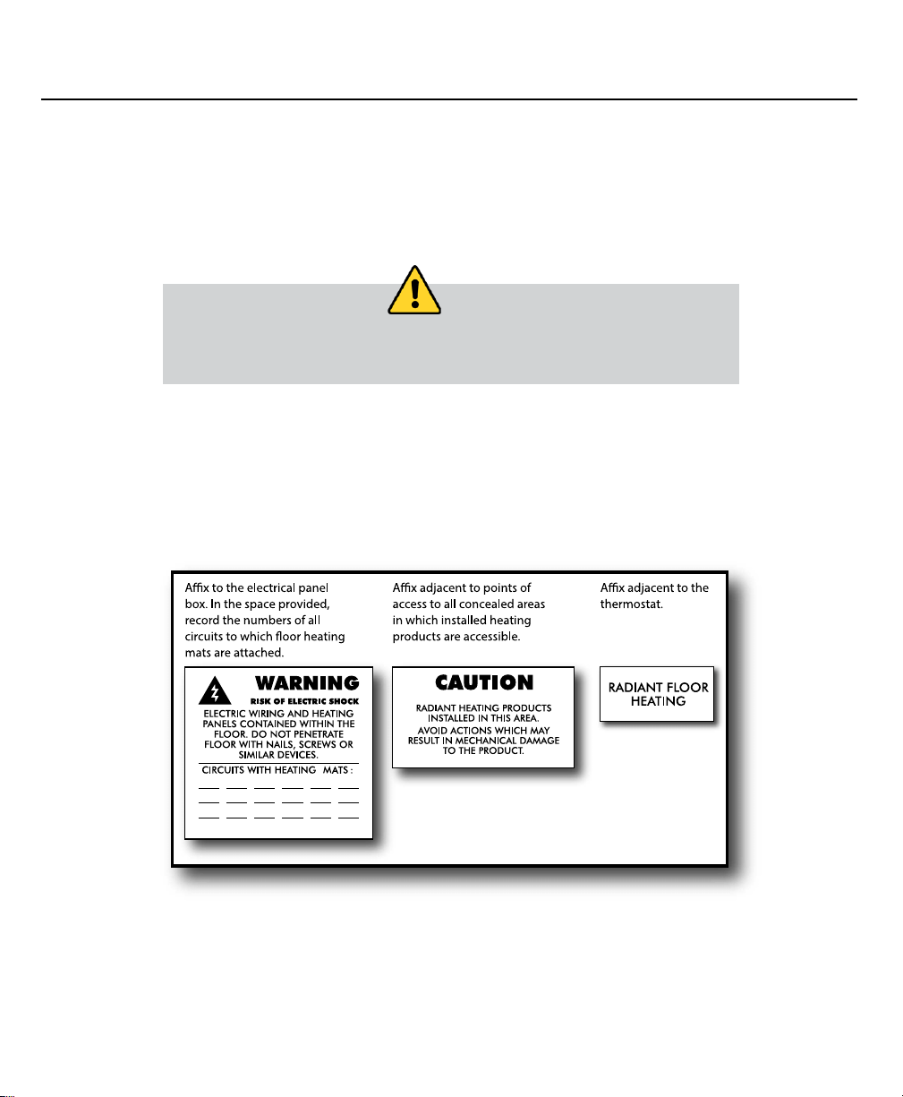
Place Caution Stickers
Apply warning stickers provided with mats in appropriate locations, as shown below. these labels are an integral
part of this heating system and must be installed for warranty to be in force.
4. Inspection and Testing Continued
Installation & Owner’s Guide 16
Install baseboards or trim around the perimeter of the room. This ensures that the
floor will not lift, exposing the mats. The flooring manufacturer’s instructions will have
information about installing the baseboard or trim to allow the floor to float properly.
NOTE:

SECTION 5. Operation
Installation & Owner’s Guide 17
Operating the System
Operation of Radiant Heat for Floating Floors is the same as other heating systems. Just set the thermostat to the
desired temperature and the system warms your finished floors and the room.
Keep the following things in mind:
• Since each room has its own thermostat, you can individually tailor room temperatures based on activity or
occupancy. For instance, if a room is rarely used, you can set its thermostat lower to conserve electricity.
• Before you leave your home for an extended period of time, lower the temperature settings to reduce the power
consumption.
• Setting the thermostat to a very high temperature will not make a room warm up faster – it will merely result
in the occupants being too hot when the set temperature is ultimately reached.
• High airflow velocities (from open doors or windows or extreme drafts) may make occupants feel cold.
• Routinely test thermostats according to their manufacturer’s instructions.
Precautions
Although the Radiant Heat Film system requires no maintenance, there are some things that must be taken into
account to ensure that the systems are not damaged. Additional information for remodeling and repair techni-
cians is available by calling 1-888-WARM PAD.
Never pierce the floor
• Piercing the electrically conductive portions of a heating mat can result in a potentially
dangerous electric shock.
• Piercing the mats will damage them and may present fire hazard.
• If a portion of the floor surface must be replaced, inspect any exposed heating mats for damage that may have
occurred while moving the flooring. See “Step 1. Inspect and Test Mats” on page 8 for complete instructions
on inspecting the mats.
• Never cover any heated portion of a floor with walls or other permanent structures.
This may trap heat and create a potential for overheating.
• If new walls or partitions are added over heating portions of a new floor, the heating mats located under the
walls or partitions must be disconnected from power to avoid a potential for overheating.
5. Operation Continued
Installation & Owner’s Guide 18
Repair/Remodel Information
Before performing any remodeling work near a heated floor, carefully read Sections 1 through 3 of this manual.
These sections detail the clearances, procedures, and materials involved as well as the testing procedures re-
quired to ensure system safety.
CAUTION:
This information must be read and understood by all repair
and remodeling technicians who will be working on the house
structure in the area of an installed Radiant Heat Film Mat or main
electrical systems. Failure to follow these guidelines may result in
a risk of electric shock or fire hazard.
CAUTION:
When installing any other
materials on or near a heated
floor, ensure that no heating
elements are punctured by
nails, screws, etc.
Notes
Date Installed:
General Contractor:
Electrical Contractor:
Flooring Contractor:

SKETCH GRID
Sketch Grid
Installation & Owner’s Guide 19

2500 Old Hadar Road
Norfolk, NE 68702
888-379-9695 • FAX 402-379-9737
Copyright © 2020
REV 0320
Radiant Heat Film
for Floating Floors