Loading ...
Loading ...
Loading ...
10 www.dimplex.co.uk
11
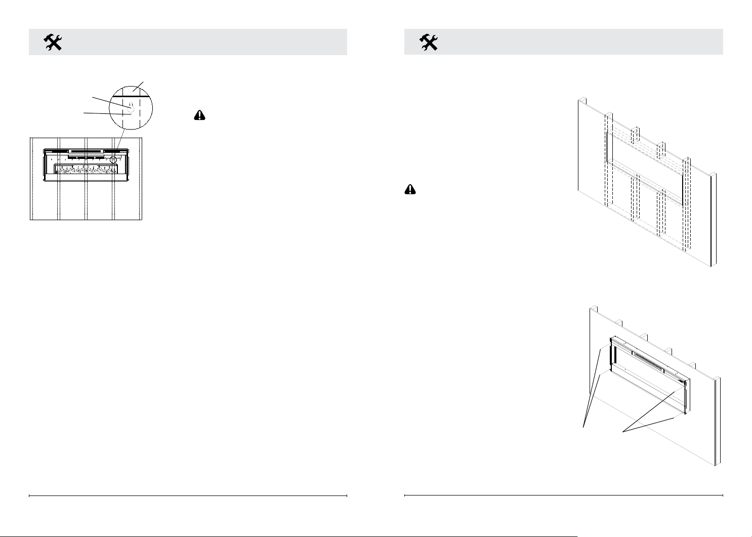
5. Mark the location of four (4)
screw locations on the wall
(through key-holes).
CAUTION: If installing unit on
a wall that is constructed of
drywall ensure that appropriate
wall anchors are used and at
least one is located into a stud.
6. Remove fireplace from wall
and store in a safe place
away from traffic.
7. Screw all four (4) supplied #8,
3.8 cm square head mounting
screws and washers into
the wall and/or wall anchors
leaving 6.5 mm of thread.
8. Align chosen key-holes with
screws and hang replace
on the wall. Screw heads
and washers will t through
key-holes and replace will
slide down into place (screws
will slide into narrow part of
key-holes).
9. Tighten all four (4) mounting
screws down on replace
chassis.
10. Screw the two (2) supplied
#8 square head screws
through two of the permanent
mounting holes which align
with a wall stud.
11. Carefully replace and install
• Lay replace on its back.
• Remove two (2) Phillips
screws from each of the two
(2) glass brackets (Figure 2).
• Remove glass brackets.
• With one hand keeping
pressure on the partially
reective glass, tilt the
replace upright and slightly
forward to allow the partially
reective glass to fall out of
the inside framing.
• Remove partially reective
glass from replace.
4. Position the replace on a wall
at the position where it will be
mounted (Figure 3). Use a
bubble level (one is supplied)
to ensure that replace is level
on the wall.
Fireplace Installation
Figure 3
Key-hole
Wall stud
Permanent
mounting hole
Fireplace Installation
partially reflective glass and
glass brackets using screws
from step 1.
12. Refer to Front Glass
Installation section, for nal
installation procedures.
In-wall Recessed
Installation - 100mm Deep
CAUTION: Two people may
be required for various steps
of this procedure.
1. Prepare a wall with a framed
opening of 118.1 cm wide x
42 cm high (Figure 4).
!
NOTE: The sizing has allowed
for 6.4mm around the replace
insert for ease of installation. This
replace does not require any
additional venting.
2. Choose your method of
supplying power to the unit:
• Plug in (you may run the
power cord out of the framed
wall opening to an existing
outlet or install an outlet on
a nearby wall stud within the
wall).
• Hard wire the replace.
!
NOTE: Hard wiring can
be done by removing the plug
from the factory tted cord and
Figure 5
Mounting
holes
Figure 4
Loading ...
Loading ...
Loading ...