PROPEL Quick Install Guide
NOTE: This device complies with Part 15 of the FCC Rules. Operation is subject to the following two conditions: (1)
this device may not cause harmful interference, and (2) this device must accept any interference received, including
interference that may cause undesired operation.
STEP 1 - Install the header end bracket (split/twin doors)
Open up the end bracket and bolt together to form a right triangle. You’ll recognize the end bracket by the extra 4”
piece of punch angle bolted to it. Identify the center of the header over the door opening. Mount the bracket using the
hardware provided. Mount the bracket 3”-12” above the bottom edge of the jamb. Connect the sway brace to the End
Bracket and to the Header. If you have split/twin doors, you will have 2 end brackets at the center of the header.
STEP 2 - Install the header Intermediate Brackets.
These brackets are mounted at the same height above the bottom of the header as the End Bracket. Open the
intermediate bracket and bolt together as shown below. Evenly space the intermediate brackets along the header. For
most doors, you’ll mount an Intermediate Bracket every 6-7 feet from the End Bracket.
NOTE: I-beam headers may require that you disassemble these brackets and use the punch angle to create brackets
that mount directly to the trusses. See photo below.
HINT: You will save time and energy if you run the wire for the photocells as you are mounting these brackets. The
wire can be run through the holes in the punch angle brackets. Be sure the wire doesn’t hang down where it can
become caught in moving parts.
STEP 3 - Mount the Door Arms
Locate the door arm and the door arm hardware bag. install the upper gussets at the upper corner of the door. As
with the lower gusset, be sure the door is closed to ensure the gussets do not interfere with each other or, in the case
of single doors, with the building.
Note: If the inside vertical door support has ridges, you may need to grind them down so that the gusset is flush
against the door. Alternatively, use washers to shim out the gusset at the leading edge so that the rest of the gusset
lies flat. Open the door fully to ensure that the gusset does not hit the building as the door retracts. Screws along the
top edge of the gusset must be flush with the gusset or the gusset may hit the building when the door closes, causing
the motor to reverse the doors.
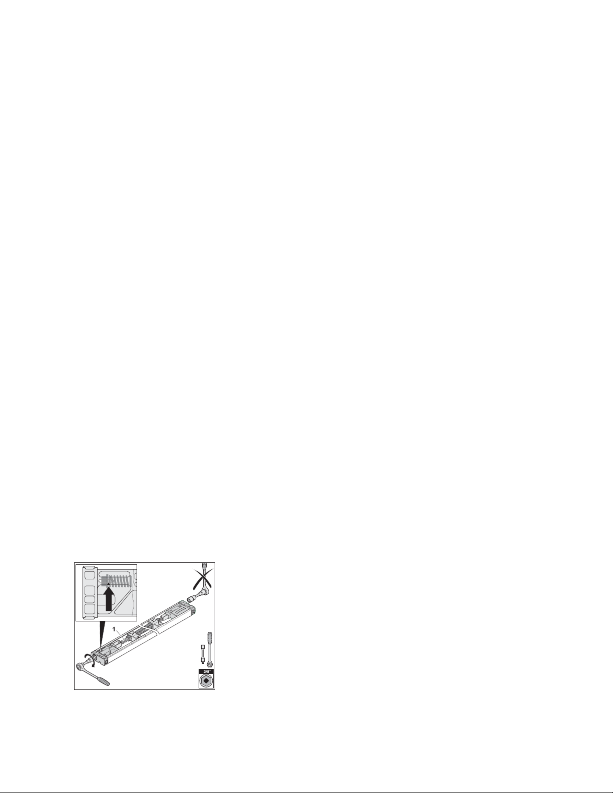
STEP 4 – Prepare the C-rail (drive track)
Rail pre-assembly
a. The chain (1) is inserted into the plastic chain channel (2). The chain channel guides the chain and also isolates
the chain from the C-rail (3). Please do not remove!
Rail mount bracket pre-assembly
b. Slide the ceiling bracket (3) onto the C-rail.
NOTE: The rail mount bracket will not slide over the connecting sleeve. Place the rail mount brackets on the
appropriate sections of track that align with the header brackets (see Step 8) before connecting the rail sections with
the connecting sleeve. You’ll want the ceiling brackets to be spaced 6-7 feet from the end of the assembled rail that is
opposite the motor.
c. Insert both C-rails into the connecting sleeve all the way to the stop position. On the C-rail end that is opposite the
motor:
d. Attach tensioner to chain and turn it by 90°
e. Insert slide-in part in the C-rail and place the tensioner into the opening of the slide-in part.
f. Place the washer and the spring on the tensioning bolt M8 x 80 mm and screw the tensioning bolt into the
tensioner (1) by hand.
18 en
9. Slide in the slide-in part (2) together with the chain (1).
Final position see graphic.
On the opposite side of the C-rail:
10. Attach tensioner (1) to chain (2) and turn it by 90°.
11. Insert slide-in part (3) in the C-rail (4) and place the ten-
sioner (1) into the opening of the slide-in part (3).
12. Place the washer (6) and the spring (7) on the tension-
ing bolt (8) M8 x 80 mm (8) and screw the tensioning bolt
into the tensioner (1) by hand.
13. Tighten the chain (1) using a 3/8“ socket wrench up to
the marking. Arrow has to line up with collar of the ten-
sioning bolt.
Caution
The pre-installed slide-in part on the opposite side has been
already pre-tensioned at the factory and must not be tight-
ened any further. Attempting to tighten further can damage or
destroy the tensioner.
14. To set the motor carriage into position (1) pull the emer-
gency release cord once (N). Then move the carriage
until it locks into place.
8. Installation
g. Tighten the chain (1) using a 3/8“ socket wrench up to the marking. Arrow has to line up with collar of the
tensioning bolt.
h. To set the motor carriage into position pull the emergency release cord once. Then move the carriage until it locks
into place.
1
STEP 6 – Hang the C-rail
NOTE: The control head is always mounted on the side the door retracts to. For example: If you are standing inside
the building looking out and the door opens to the right, the control head goes on the right side, too. Likewise, if the
door opens to the left, the control head is mounted to on the left side.
a. Attach the rail end bracket to the end bracket bracket so that the center of the rail is in line with the door arm. Be
sure push the screws up through the bottom of the holes.
b. Close the doors so that the door arm is near the center bracket. The door arm can provide a resting place for the
rail, but be careful that the rail doesn’t slide off.
c. Walk the opener rail up the ladder to the header.
d. Slide the C-rail into the center header bracket and secure with the pin. Attach locking c-clips to secure.
e. Attach rail to remaining header mounting brackets using the ceiling brackets
Note: The rail and control box will extend beyond the jamb header bracket by about 4 feet, depending on the
size of your opening.
STEP 7 – Connect the motor carriage to the door arm
a. Attach the j-bar to the motor carriage. Guide the bolt, (long) through the holes in the motor carriage and the door
arm. Secure with the locking c-clip.
b. Connect the j-bar to the door arm using the angle bracket attached to the door arm.
STEP 8 – Wall Station & Photocells
Mount the wall station. The most common mounting location is the inside face of the jamb. The distance to the floor
must be at least 5’ so that children cannot reach the wall station. The wall station is programmed just like the 4-button
remote control (see below).
Select the mounting location:
• outside of the range of motion of the door and opener mechanics
• so the user can see the door directly
• when operating the wall station, the user can remain outside of the range of motion of the door and opener
mechanics on a flat surface
Install the Photo Eyes
a. Look for a suitable installation position for the mounting bracket inside the building to the left and the right of the
door. Typically, the photo eyes are mounted to the door jambs, about 18” off of the floor.
b. Hold the mounting bracket to the wall and mark the mounting points. The height and angle of the bracket can be
adjusted through the slotted holes.
c. Drill holes for the plywood screws.
d. Screw in two plywood screws 6 x 40 mm.
e. Pre-attach the carriage bolt M6 and the wing nut M6 to the mounting bracket.
f. Slide the transmitter over the head of the carriage bolt M6 and tighten the wing nut M6. The position of the photo
eyes can be adjusted through the slotted holes.
g. Mount the receiver on the opposite side in the same way.
h. Run the two sets of wires from the photo eyes to the control housing.
i. Use staples to keep wires in place.
Connect photo eyes to the control housing.
a. Remove the red cover of the control housing
b. Strip off insulation approx. 3/8” from the wire ends (transmitter and receiver).
28 en
6. Slide the transmitter (4) over the head of the carriage
bolt M6 (1) and tighten the wing nut M6 (2). The position
of the photo eyes can be adjusted through the slotted
holes (5).
7. Mount the receiver on the opposite side in the same way.
8. Run the two sets of wires (6) from the photo eyes to the
control housing.
9. Use staples to keep wires in place.
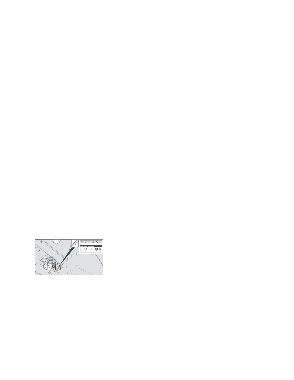
10.5. Connection
Connect photo eyes to the control housing
1. Remove the red cover (1) of the control housing (2).
2. Strip off insulation approx. 3/8“ (10 mm) from the wire
ends (transmitter and receiver).
2
1
14
15
16
R
13
3
4
5
6
1
3
2
3. Guide both sets of wires (1) from the outside through the
opening (2) into the control housing (3).
4. Connect one wire of the transmitter to terminal 5 and the
other wire to terminal 6.
5. Connect one wire of the receiver to terminal 5 and the
other wire to terminal 6.
Note
If you have inadvertently inserted a wire end incorrectly,
you can open the terminal using a small slotted screwdriver
(press down) and pull out the wire end.
10. Photo Eyes
c. Guide both sets of wires from the photocells through the opening into the control housing.
d. Connect one wire of the transmitter to terminal 5 and the other wire to terminal 6.
e. Connect one wire of the receiver to terminal 5 and the other wire to terminal 6.
Adjusting the photo eyes
If the LED in the photo eye transmitter lights up continuously green and the LED in the receiver lights up red, the
photo eyes are set correctly. Only the functioning must now be subsequently checked, please see “Testing the photo
eyes function.” If both LEDs do not light up continuously, the photo eyes have to be adjusted as follows: Loosen the
wing nut either on the transmitter or the receiver and adjust the position until both LEDs light up continuously. By
loosening the screw, the adjustment angle can also be changed.
STEP 9 – Install the Control Head
a. Make sure the contact on the slide in part faces down.
b. Slide the control housing all the way onto the rail.
c. Slide in the fastening plastic bolt all the way through the hole of the control housing.
d. Turn the fastening bolt a half turn in the clockwise direction up to the stop position using a medium slotted-
screwdriver (see graphic). If a half turn is not possible, the control housing is not correctly attached to the C-rail.
Move the control housing slightly while sliding in the fastening bolts up to the stop position.
2

e. The electrical contact is established after connecting the control housing to the C-rail. The two contacts supply
power (24V) to the motor carriage.
Caution: Do not operate the door until you have set the limit stops. Operating the door prior to setting the limits will
result in damage to your system, door, and/or building.
STEP 10 – Set the limit stops
a. Close the door by hand.
b. Slide the limit (with the V marking) all the way to the carriage motor until you hear a click.
c. Tighten the screw with a phillips screwdriver.
d. Open the door by hand.
e. Loosen the screw on the limit stop (with the H marking) using a phillips screwdriver and slide the limit stop all the
way back to the carriage motor until you hear a click
f. Tighten the screw with a phillips screwdriver.
STEP 11 - TEST THE OPERATOR
Program the remote transmitters and wireless wall station
In order to open, close or stop the opener using the transmitter, the opener has to “learn” the code first. The radio
code of the transmitter is transmitted to the receiver (inside the control housing). Plug in the power plug into the
power outlet
Learning the radio code
a. Press the learn button once on the control housing.
The LED (Radio) is solid.
b. Press a desired transmitter button. The LED (Radio) flashes briefly.
If the LED (Radio) lights up for a second, the transmitter has been learned.
Operating the opener with the wall station: Opening, closing, and stopping the door
a. To open and close, press the button once. The door opens or closes depending on the starting position. The light
switches off automatically after 180 seconds.
b. To stop, press the button during the open/close procedure once. The next press of the button causes the door to
move back to its respective position.
c. The door arm and boot should not contact the jamb when the door opens. Adjust the limit stops if necessary.
Learning the forces of the door
When the opener is initially connected to the main supply, the opener lights blink. This indicates that the opener is
ready to learn the forces of the door.
After the completion of two full cycles (four door movements) the lights will stop blinking.The opener controller
automatically detects the required force each time the door moves. If an obstacle (i.e. a person or a vehicle) blocks
the door’s movement, in the closing direction: the door will reverse automatically; in the opening direction: the door
will stop.
a. Press the Reset button on the control housing until the “Status” LED turns off. The LED “Status” blinks while being
pressed.
b. Release the Reset button.
The light and the LED “Status” blink.
c. Operate the door two full cycles. The light stays on. The learning process is completed.
The light will turn off after approx. 180 seconds.
Test the emergency release
a. Close the door.
b. Attach the provided chain to the emergency release cored.
c. Pull on the emergency release chain once.
When functioning correctly, the carriage is now unlocked and the door can now be moved by hand.
Test the obstacle detection function
After the force has been learned, the obstacle detection must be checked. The door must change directions after
contacting a 1“ (25,4 mm) high object placed against the door jamb.
a. Open the door with the opener
b. Place an approx 1” object (a short 2x4 piece of wood will do) on the floor at the opposite door jamb
c. Close the door with the opener. When the door contacts the object, it must stop immediately and reverse
completely. If the door does not reverse,check the basic settings of the limit stop, see chapter “Installation”. In all
other cases, the opener is defective and must be repaired or replaced. Consult your qualified dealer for advice.
Test the photo eyes function
a. Close the door with the opener. Hold a 6“ high white object during the closing procedure in between the photo eyes
to disrupt the infrared beam. The door must stop immediately and then reverse entirely. The photo eyes are
functioning properly, if the LED lights of both photo eyes are solid
b. If the door does not stop, check the following:
• if the housing of the photo eyes are dirty,
• whether transmitter and receiver are correctly aligned with each other,
• whether the cables are damaged or loose.
STEP 14 – Install Cinchers
The cincher plate is mounted to the jamb above a door girt (crossmember) about 4-5 feet above the floor.
3

a. Check to make sure your girt is level as the door opens and closes.
b. Fasten the cincher plate to the jamb such that the vertical pin is near the middle of the girt and the strap is angled
slightly upward, about 5º, toward the door. The bottom of the pin should be about 1/2” above the girt. If your girt is
not level, you may need to raise (or lower) the plate before fastening it to the jamb.
NOTE: In this application you should mount the Cincher so that the flat part of the black plate is against the jamb.
c. Fasten the edge of the cincher rail nearest to the boot. It should be flush with the edge of the girt, but must not
protrude beyond the girt.
d. Pull the door in toward the building. At the same time, push the other end of the cincher rail against the pin and
securely fasten it to the girt.
e. Before placing screws in the remaining cincher rail holes, check the motion of the door. The pin should contact the
cincher rail in the last few inches of travel. The door should be tight enough that it doesn’t move in and out, but not
so tight that it restricts door movement.
If necessary. adjust the angle of the cincher rail. Once you are satisfied with the angle, use screws in the remaining
cincher rail holes to secure the rail.
STEP 15 – Programming the Wall Station & Remote
Press the learn button (1) once on the control housing. The LED (Radio) is solid.
Press a desired transmitter (remote or wall station) button. The LED (Radio) flashes briefly. If the LED (Radio) lights
up for a second, the transmitter has been learned.
Programming additional transmitters. Repeat the above steps. A maximum of 20 button/storage locations for each
radio receiver are available.
If no radio code is received within 10 seconds, the learning process is interrupted and has to be started again if
necessary.
STEP 16 – Test the System.
Wind Warning: Never open doors covering more than one opening at a time! Due to the size and construction
of sliding doors and the effect of wind on these doors, it is critical that only one building opening be open at
a time.
For example, many buildings have an opening on an end wall and another opening on a side wall. The side
wall door(s) must be closed before you open the end wall door(s). Similarly, the end wall door(s) must be
closed before you open the side wall door(s).
Failure to follow these instructions could result in serious or fatal injuries and significant damage to your
building, as well as your Propel Doors system. Please note that wind damage is not covered by your Propel
Doors warranty.
a. Attach the following warning labels: finger pinch sticker (cincher plate); foot hazard sticker (lower gusset),
b. Manually open and close the door completely. check if the door runs easily.
c. Make sure all screws and attachments are tight.
d. Engage the motor by pulling the emergency release cord.
e. Plug in the controller.
Operating the opener with the transmitter
The transmitter has a range up to 100 ft (30 m) depending on the surrounding area. When closed, the transmitter is
protected by a stainless steel case to prevent an unintended operation.
a. To access the buttons, slide the transmitter body out of the stainless steel case. There are positions for each
button (a total of 4 buttons).
b. To close the transmitter body, slide it back into the stainless steel case up to the stop position.
Opening, closing, and stopping the door
In order to operate the opener using the transmitter, this opener function first has to “learn in” the code of a particular
transmitter. See “Program the transmitter”.
a. To open and close the door, press the corresponding button on the transmitter one time (e.g. button 1). Depending
on the starting position, the door either opens or closes. The light switches off automatically after 180 seconds.
b. To stop the door, press the corresponding transmitter button during the open/close procedure.
Pressing the transmitter button again causes the door to move back to its respective starting position.
PROPEL
ph 888-391-8592
fax 888-391-8595
7 Kemp Dr, Ste C
Chatham, IL 62629
www.propeldoors.com
4