Loading ...
Loading ...
PB112 400-112-006-C 26/2/07 1/1
n One (1) power base
o Two (2) screws
p Four (4) solderless connectors for copper wires
NOTE: Special CO/ALR solderless connectors must be used for connecting
aluminum conductors.
Option
q One (1) AC112-01 floor sensor (ordered separately; required for floor
heating applications only)
Turn off power to the heating system at the main electrical panel to
avoid electrical shock. The installation should be carried out by an elec-
trician.
NOTE: This power base must be used with thermostat operating on
15-minute cycles.
High voltage thermostats must be installed onto an electrical box.
The following guidelines are not necessary for floor heating applica-
tions:
For a new installation, choose a location about 1.5 m (5 ft) above the
floor and on an inside wall.
The thermostat must be installed on an inside wall facing the heating
system.
Avoid locations where there are air drafts (top of staircase, air outlet),
dead air spots (behind a door), direct sunlight or concealed chimneys or
stove pipes.
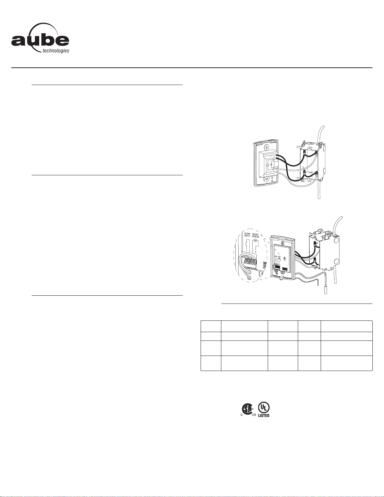
n Connect the power base wires to the power supply and load using sold-
erless connectors for copper wires (figure 1).
o For floor heating applications, insert the floor sensor wires through one
of the two holes below the terminals (figure 2) and connect the wires to
terminals 3 and 4 (no polarity).
NOTE: The wires must run alongside the terminals and not go over
them. The wire must not cross any heating wires nor be placed directly
on a heating wire or adjacent to it. For best performance, the sensor
probe should be centered between the wires in the mat.
WARNING: This power base does not have a built-in ground protection
device. Therefore, for floor heating applications, you must install a sepa-
rate ground protection device at the main electrical panel. Contact your
Aube authorized representative if you need a thermostat with built-in
ground protection device.
p If you wish to use a remote controller such as the CT240 or CT241,
insert the cable (use 18 to 22 gauge flexible wires) into one of the two
holes available below the terminal board and connect to terminals 1 and
2 of the base (figure 2).
q Push the excess length of the high-voltage wires back into the electrical
box.
r Secure the power base to the electrical box using the provided screws.
s If necessary, set the configuration switches on the control module (refer
to the control module user guide).
t Install the control module onto the base.
u Apply power to heating system.
Storage: -4°F to 120°F (-20°C to 50°C)
Remote controller input (ECONO): requires a dry contact
Size (H•W•D): 4.89 x 2.76 x 0.91 in. (124 x 70 x 23 mm)
Certifications:
n
Parts
1.
o
Guidelines
2.
p
Procedure
3.
q
Technical Specifications
4.
Model Supply Max. Load Power Wiring
120S 120 VAC, 50/60Hz 16.7 A 2000 W 4 wires / single pole
240S
240 VAC, 50/60Hz
208 VAC, 50/60Hz
16.7 A
4000 W
3475 W
4 wires / single pole
240D
240 VAC, 50/60Hz
208 VAC, 50/60Hz
15 A
3600 W
3120 W
4 wires / double pole
Power
Load
Figure 1
Figure 2
PB112
Installation Instructions
For models: 120S / 240S / 240D
400-112-006-C (PB112-120-240) ENG.fm Page 1 Monday, February 26, 2007 1:32 PM