cadetheat.com Tel: 360-693-2505 PO Box 1675 Vancouver, WA 98668-1675
Benets You Can Depend On
SAVE THESE INSTRUCTIONS
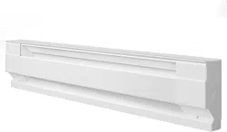
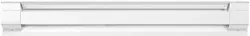
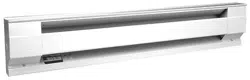
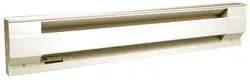
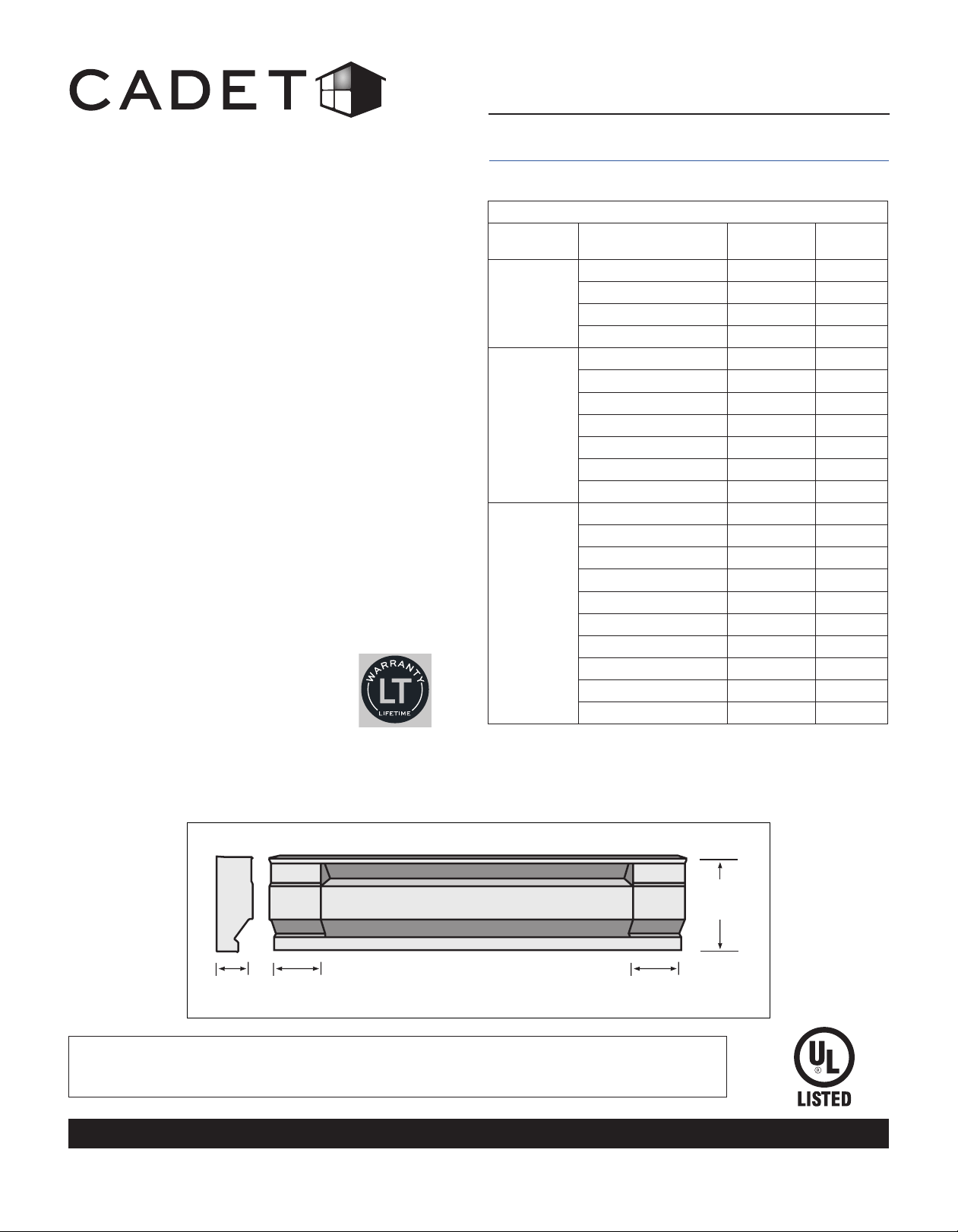
Electric Baseboard Heater
Owner’s Guide
6¾"
17.15cm
2½"
6.35cm
Side
Front
3¾"
9.53cm
3¾"
9.53cm
TOOLS REQUIRED:
• Phillips Screwdriver
• Straight Screwdriver
• Wire Strippers
• Drill or Hammer
• Drill Bits
• (4) Wood Screws
• Wire Connectors
• Strain Relief Connector
• Practical design is silent and built to last
• Easy installation with pre-punched
knockouts at 1-inch intervals
• Universal wiring available on either left or
right end
• Place under a window for convection to
naturally circulate warm air in your room
• Rest easy—includes high-temperature
safety shutoff feature
• Durable, powder-coated nish stands up to
nicks and scratches
• Your Cadet electric baseboard heater has
been thoroughly tested and is guaranteed
with a limited lifetime warranty
Electric Baseboard Models
Line
Voltage
Model Watts Amps
120
2F500-1 500 4.2
3F750-1 750 6.3
4F1000-1 1000 8.3
6F1500-1 1500 12.5
208
2F500-8 500 2.4
3F750-8 750 3.6
4F1000-8 1000 4.8
5F1250-8 1250 6.0
6F1500-8 1500 7.2
8F2000-8 2000 9.6
8F2500-8 2500 12
240
(1)
2F350 350 1.5
2F500 500 2.1
3F750 750 3.1
4F1000 1000 4.2
5F1250 1250 5.2
6F1500 1500 6.3
8F2000 2000 8.3
8F2500 2500 10.4
8F2025 2000/2500 8.3/10.4
10F2500 2500 10.4
(1)
240 volt models can be used at 208 volts. Wattage equals 75% of 240v rated
wattage.
http://www.cadetheat.com/products/baseboard-heaters/baseboard
Note: A wall thermostat or built-in thermostat kit is
required for comfortable warmth and control
Page 1
SAVE THESE INSTRUCTIONS
cadetheat.com Tel: 360-693-2505 PO Box 1675 Vancouver, WA 98668-1675
IMPORTANT INSTRUCTIONS
before you begin, you should know...
1. Read all instructions before using this heater.
2. A heater has hot and arcing or sparking parts
inside. Do not use it in areas where gasoline,
paint, or ammable vapors or liquids are used or
stored.
3. This heater is hot when in use. To avoid burns,
do not let bare skin touch hot surfaces. If provided,
use handles when moving this heater. Keep
combustible materials, such as furniture, pillows,
bedding, papers, clothes, and curtains away from
heater.
4. To prevent a possible re, do not block air
intakes or exhaust in any manner. Do not use on
soft surfaces, like a bed, where openings may
become blocked.
5. Do not insert or allow foreign objects to enter
any ventilation or exhaust opening as this may
cause an electric shock or re, or damage the
heater.
6. Save these instructions.
When using electrical appliances, basic precautions should always be followed to reduce the risk of re,
electric shock, and injury to persons, including the following:
...about the Cadet Electric Baseboard
...a thermostat is required
A Cadet wall thermostat is recommended for optimum performance, or you may prefer the convenience of a built-in thermostat kit.
For instructions on wiring a thermostat, see the instructions that were included with your thermostat. If you are installing a wall ther-
mostat, refer to the section later in this guide titled “Baseboard Wiring With a Wall Thermostat” prior to installing the baseboard.
For best results, install the baseboard heater under a window, along an outside wall, or as close as possible to an outside door.
Follow these instructions for selecting an ideal area of installation:
DO NOT INSTALL ANY BASEBOARD BELOW AN ELECTRICAL OUTLET
DO NOT INSTALL ANY BASEBOARD VERTICALLY. MOUNT THE BASEBOARD HORIZONTALLY ONLY
The seam at the junction of the wall and oor behind the heater should be caulked to prevent dust from being drawn into the room.
Heater should be set ush against surface of the wall.
Remove any obstructions between the back of the unit and the surface of the wall.
Baseboard heater may sit directly on any oor surface, including carpet. Do not allow carpet to block lower air intake located 1 inch
from the bottom.
Maintain at least 12 inches minimum clearance from objects hanging above (i.e. drapes).
...that voltage on all models is important
It is extremely important that you verify the electrical supply wires are the same voltage as the heater (i.e. 120 volt heater to 120 volt
power supply and 240 volt heater to 240 volt power supply). If replacing an existing heater check the labels of the old heater and
replace using same voltage. Hooking a 240 volt heater to a 120 volt power supply will drastically reduce the heater’s output. Hooking
a 120 volt heater to a 240 volt power supply will destroy the heater.
...placement
...wiring for Model 8F2025
Model 8F2025 is a multi-watt unit that can be congured for either 2500 or 2000 watts. The heater is factory set for 2500 watts, but
the instructions vary depending on your desired wattage and which side you are wiring. Make sure you follow the directions in the
Owner’s Guide for your specic application. It is best to decide on your desired wattage prior to installing the baseboard.
The Cadet Electric Baseboard is designed to provide zonal heat to a room by using convection to naturally circulate warm air. Safety
is Cadet’s rst priority. All F-Series electric baseboards feature an oversized high temperature limit switch with a full length capillary
sensor tube that temporarily shuts the heater off when excessive operating temperatures are detected. For effective and safe opera-
tion, and to prolong the life of the heater, read all instructions and safety information, and follow the maintenance instructions in this
Owner’s Guide.
See our How-To Video at
http://cadetheat.com/support/install-help
...wiring
Wire connection is possible from either right or left side of the baseboard heater. Determine on which side of the baseboard you are
making wire connections by locating the supply wires. You must locate the supply wires before mounting the heater. See section titled
“Baseboard Wiring With a Wall Thermostat” prior to wiring the baseboard if you are installing a wall thermostat.
Page 2
INSTALLATION INSTRUCTIONS
1. All electrical work and materials must comply
with the National Electric Code (NEC), the Occu-
pational Safety and Health Act (OSHA), and all
state and local codes.
2. Use copper conductors only.
3. Do not install below an electrical receptacle.
4. Do not install the heater against combustible
low-density cellulose berboard.
5. A heater has hot and arcing or sparking parts
inside. Do not use it in areas where gasoline,
paint, or ammable vapors or liquids are used or
stored.
6. Heater should be set ush against surface of
the wall.
7. Remove any obstructions between the back of
the unit and the surface of the wall.
8. Baseboard heater may sit directly on any oor
surface, including carpet.
9. Maintain at least 12 inches minimum clearance
in front of baseboard, and from objects hanging
above (i.e., drapes), and 6 inches minimum on
both sides.
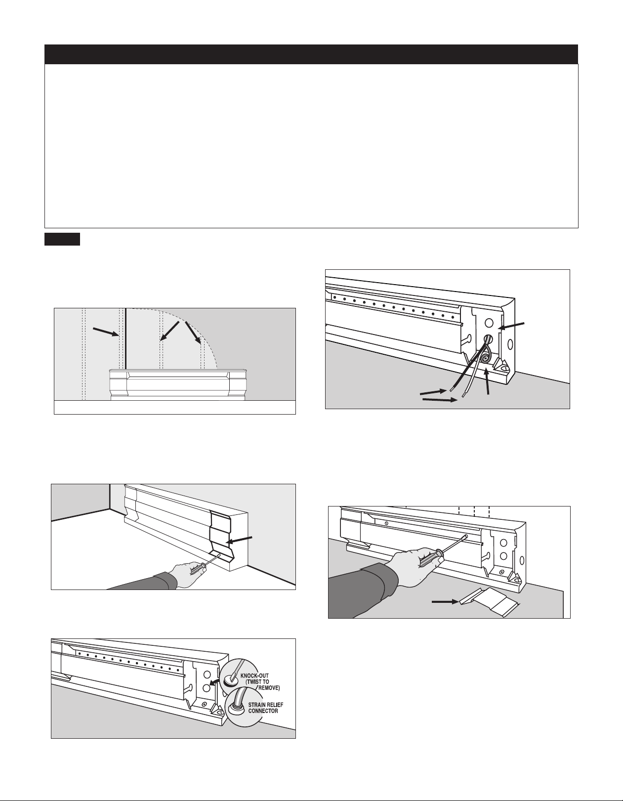
1. Locate wall studs closest to supply wires and position heater
(See Figure 1). NOTE: Wire connection is possible from either
right or left side of the baseboard heater.
IMPORTANT! DO NOT DISCONNECT ANY OF THE BASE-
BOARD’S FACTORY WIRE CONNECTIONS UNTIL YOU ARE
READY TO BEGIN WIRING!
STEP 1
Mount Heater to Wall
Figure 1
Figure 2
Figure 3
2. Remove the wiring compartment cover by removing the screw
(See Figure 2). The wiring compartment is an approved junction
box for the baseboard only. No additional junction box is required.
4. Pull supply wires through the connector and secure leaving 6
inch wire leads for later use (See Figure 4).
Figure 5
3. Remove the slotted knockout closest to the sup ply wires and
install a strain relief connector (See Figure 3).
5. Mount the heater securely to the wall with nails or screws going
into at least two wall studs (See Figure 5). The back of the heater
has “star punch” dimples that allow nails or screws to easily pierce
the sheet metal.
NOTE: You do not need to remove the front cover or disas-
semble any additional parts to mount the heater.
Figure 4
6. Connect the grounding lead to the grounding screw on which-
ever side you are wiring (See Figure 4). Both sides of the heater
include a grounding screw.
Page 3
Finished
Wall
Supply
Wire
Wall Studs
Floor
Wiring
Compartment
Cover
Junction
Box
Ground Screw
Supply Wires
Wiring
Compartment
Cover

INSTALLATION INSTRUCTIONS (continued)
AB
GROUND
DO NOT DISCONNECT
AB
GROUND
DO NOT DISCONNECT
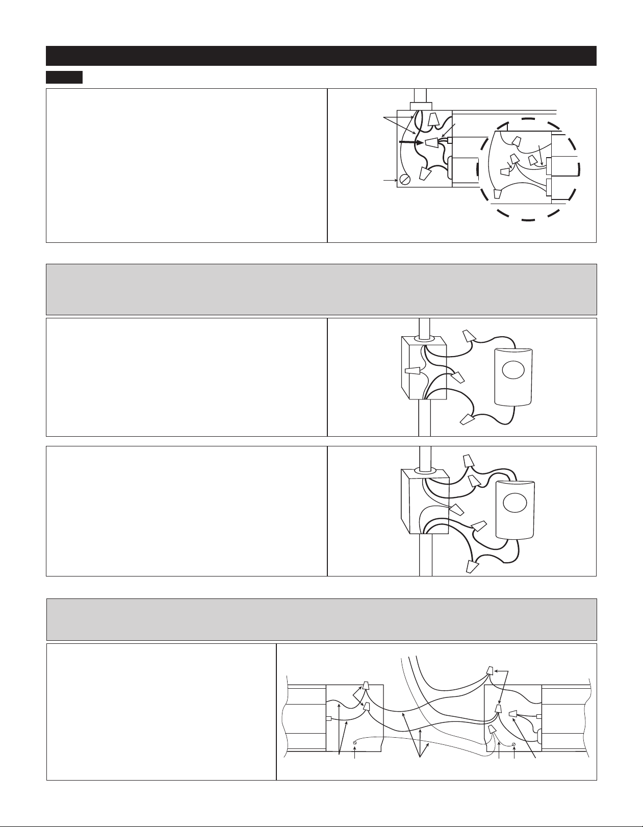
Refer to the wiring diagram below that corresponds to your heater application.
For all baseboards except Model 8F2025, refer to “Standard Baseboard.” For Model 8F2025, refer to “Multi-Watt Baseboard.”
(Important: connect supply ground wire directly to one of the ground screws provided on either side of the baseboard heater.)
Figure 8
Figure 9
RIGHT Side
Wiring Shown
Figure 6 Figure 7
STEP 2
Baseboard Wiring
1. Verify the electrical supply wires are the same voltage as the heater. Check heater specications to ensure correct wiring. Failure to
do so may destroy the heater and void your warranty. Both 120 volt and 240 volt baseboard wiring utilize three supply wires.
120 volt baseboard wiring: 1 hot, 1 neutral and 1 ground.
240 volt baseboard wiring: 2 hot and 1 ground. No neutral needed.
For all baseboard wiring applications, each of the supply wires must be connected to at least one (1) heater wire.
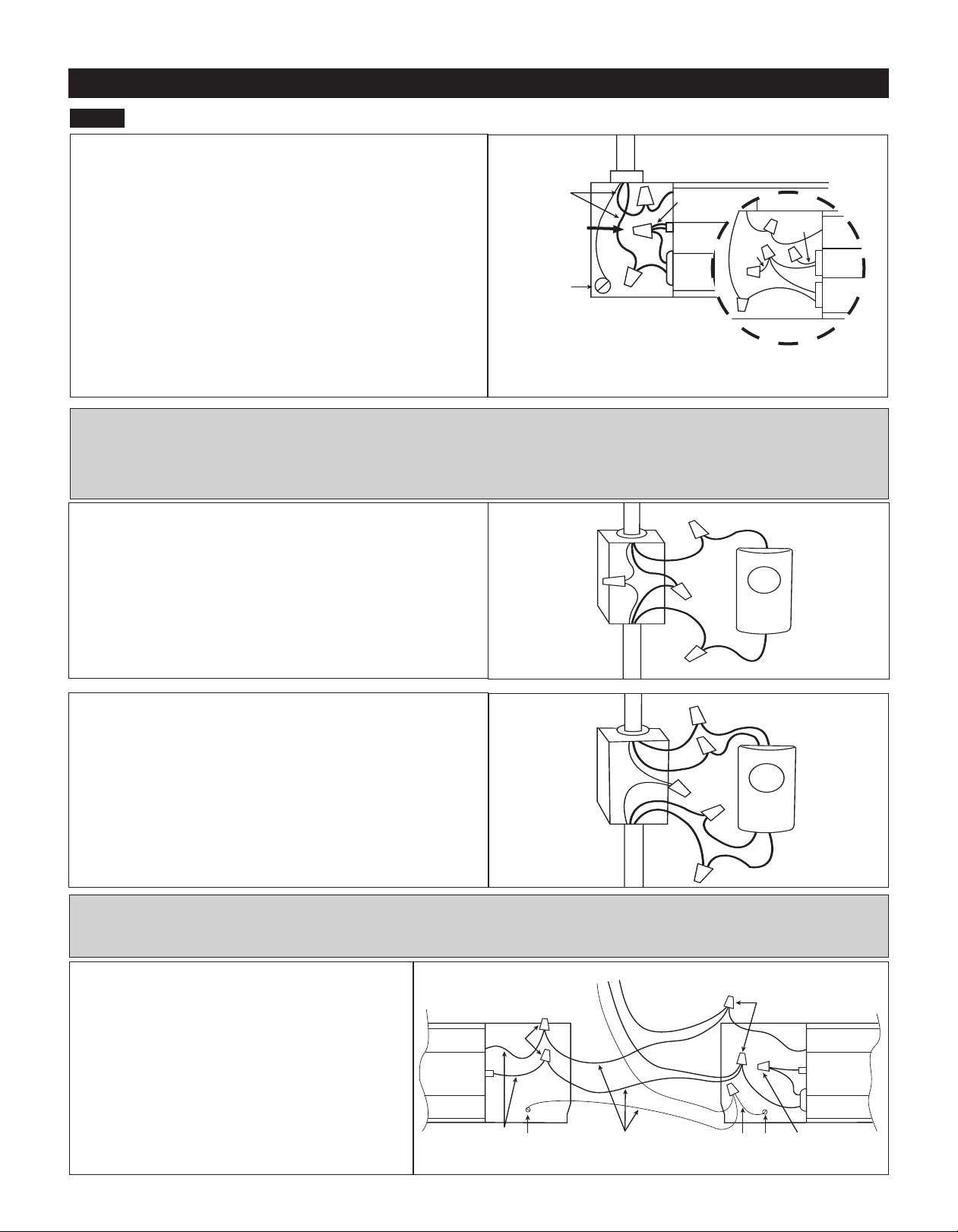
2. Disconnect ONLY ONE factory connector and ONLY on the side you will be wiring (See Figure 6; for Model 8F2025 See Figure 7). If
wiring on the left side, disconnect ONLY factory connector A. If wiring on the right side, disconnect ONLY factory connector B.
NOTE: There are no loose wires provided with the baseboard. This is due to the ability to wire the baseboard on either the right or left
side of the heater.
3. Proceed to the next step.
STANDARD BASEBOARD WIRING ON RIGHT SIDE
120V OR 240V SUPPLY (See Figure 8)
1. Connect one supply wire to one heater wire.
2. Connect remaining supply wire to remaining heater wire.
3. Replace wiring compartment cover and secure with screw previ-
ously removed.
4. Turn power back on at the electrical panel board.
STANDARD BASEBOARD WIRING ON LEFT SIDE
120V OR 240V SUPPLY (See Figure 9)
1. Connect one supply wire to one heater wire.
2. Connect remaining supply wire to remaining heater wire.
3. Replace wiring compartment cover and secure with screw previ-
ously removed.
4. Turn power back on at the electrical panel board.
MULTI-WATT BASEBOARD WIRING ON RIGHT SIDE
MODEL 8F2025 ONLY (See Figure 10)
1. Connect one supply wire to one heater wire.
2. Connect remaining supply wire to remaining heater wire.
3. Replace wiring compartment cover and secure with screw previ-
ously removed.
4. Selecting desired wattage:
a. For 2500 watt applications: No action is required. Heat-
er is factory set for 2500 watts.
b. For 2000 watt applications (inset): Remove left wiring
compartment cover. Cut red wire and cap both loose ends with
approved wire connectors, or wrap both loose ends with electrical
tape. Replace wiring compartment cover and secure with screw
previously removed.
5. Turn power back on at the electrical panel board.
Figure 10
LEFT Side
Wiring Shown
RIGHT Side
Wiring Shown
Model
8F2025
only
DO NOT DISCONNECT!
Page 4
Supply Wires
Ground Screw
Supply Wires
Ground Screw
To Supply
To Supply
Supply Wires
Ground Screw
2000 Watt Conguration
Left Side of Baseboard Shown
red wire
red
wire
To Supply
Baseboard Heater
Baseboard Heater
Baseboard Heater
Side A
Side B
Side B
INSTALLATION INSTRUCTIONS (continued)
C
B
A
C
B
A
OFF
LOW
Figure 12
Figure 13
Figure 14
MULTI-WATT BASEBOARD WIRING ON LEFT SIDE
MODEL 8F2025 ONLY (See Figure 11)
1. Disconnect splice/wire connector without the red wire.
2. Connect one supply wire to the upper black wire.
3. Connect the other supply wire to the lower black wire.
4. Selecting desired wattage:
a. For 2500 watt applications: No action is required. Heater is
factory set for 2500 watts.
b. For 2000 watt applications (inset): Cut red wire and cap both
loose ends with an approved wire connector, or wrap loose ends
with electrical tape. Replace wiring compartment cover and secure
with screw previously removed.
5. Turn power back on at the electrical panel board.
Figure 11
Left Side
Wiring Shown
BASEBOARD WIRING WITH A WALL THERMOSTAT - OPTIONAL
Refer to the wiring diagram below that corresponds to your thermostat application. Note: Wiring diagrams are for reference
only. See wall thermostat instructions included with your thermostat for your specic application.
For instructions on wiring using a built-in thermostat, see Cadet BTF1, BTF2 and SBFT2 Installation Instructions.
STEP 2
Baseboard Wiring (continued)
Single Pole Wall Thermostat (Figure 12)
1. Route supply wires to the thermostat wiring box (if not already
present).
2. Connect one supply wire to one thermostat wire (typically
marked L1).
3. Route remaining thermostat wire (typically marked T1) to the
baseboard heater.
4. Route remaining supply and ground wire to the baseboard
heater.
5. Follow installation instructions for mounting and wiring base-
board heater.
Double Pole Wall Thermostat (Figure 13)
1. Route supply wires to the thermostat wiring box (if not already
present).
2. Connect one supply wire to one thermostat wire (typically
marked L1).
3. Connect remaining supply wire to other thermostat wire (typically
marked L2).
4. Route remaining thermostat wires (typically marked T1 and T2)
to the baseboard heater.
5. Route ground wire to the baseboard heater.
6. Follow installation instructions for mounting and wiring base-
board heater.
MULTIPLE BASEBOARD WIRING. 240V SUPPLY
ONLY (See Figure 14)
1. Left side wiring: disconnect factory connector A.
Right side wiring: disconnect factory connector B.
2. Connect one wire from each heater to one supply
wire.
3. Connect remaining wire from each heater to the
remaining supply wire.
4. Connect supply ground wire to both ground screws
using appropriate guage wire.
Note: Field wiring is not provided
MULTIPLE BASEBOARD WIRING - OPTIONAL
Follow the instructions below if you are wiring more than one heater in parallel on same circuit.
If you are wiring multiple baseboards to one control, it is recommended that you use one control per room.
DO NOT DISCONNECT!
DO NOT
DISCONNECT!
Heater
Wires
Ground
Screw
To Wall Thermostat
Baseboard
Heater Right
Side
B
Baseboard
Heater Left
Side
Field Wiring
Field
Wiring
Ground
Screw
A
Supply Wires
Ground Screw
2000 Watt Conguration
Left Side of Baseboard Shown
red wire
red
wire
To Supply
red
wire
Model 8F2025
Factory set for
2500 Watts
Baseboard Heater
Side A
To Supply
To Supply
To Heater
To Heater
Thermostat
Wiring Box
Thermostat
Wiring Box
Single Pole
Thermostat
Double Pole
Thermostat
L1
L1
L2
T1
T1
T2
Page 5

OPERATING INSTRUCTIONS
MAINTAINING YOUR HEATER
WARNING! Before cleaning, turn the electrical power off at the electrical panel board (circuit breaker
or fuse box). Lock or tag the panel board door to prevent someone from accidentally turning the power
on while you are working on the heater. Failure to do so could result in serious electrical shock, burns,
or possible death.
1. The heater must be properly installed before it
is used.
2. DANGER: High temperatures may be gener-
ated under certain abnormal conditions. Do not
partially or fully cover or obstruct the front of this
heater.
3. If the heater over temperature limit trips more
than once per day, the heater must be replaced.
4. Clean heater at least every 24 months or as
required. See “Maintaining Your Heater” section.
5. Any other service not detailed in this Owner’s
Guide should be performed by an authorized ser-
vice representative.
Maintenance As Needed, or every 24 months minimum.
1. It is important that you verify power has been turned off and no
power is going to the heater before proceeding. Circuit breakers
are often not marked correctly and turning the wrong breaker off
could mean electricity is owing to the heater, even if the heater
does not appear to be working. If you are uncomfortable working
with electrical appliances, unable to follow these guidelines, or do
not have the necessary equipment, consult a qualied electrician.
2. Once you verify the power has been turned off correctly, pro-
ceed to the next step.
3. Remove cover.
4. Wash cover with hot soapy water and dry immediately.
5. Use a hair dryer, or vacuum on blow cycle, to blow debris
through the element (do not touch element).
6. Vacuum area without touching the element.
7. Replace cover and secure.
8. Turn thermostat to desired setting.
9. Turn power back on at the electrical panel board.
How to operate your heater
The room temperature is controlled by a line voltage thermostat located either on the wall, or on the heater. Once installation is com-
plete and power has been restored, if you have a mechanical thermostat, follow steps 1 through 3 below. If you have an electronic
thermostat, follow the instructions in the programming and operating guide included with your thermostat.
1. Turn the thermostat fully on.
2. When the room reaches your comfort level, turn the thermostat knob counterclockwise until the heater turns off. The heater will
automatically cycle around this preset temperature.
3. To reduce the room temperature, turn the knob counterclockwise. To increase the room temperature, turn the knob clockwise.
PLEASE NOTE: Upon initial start-up, the heater may emit a burning odor. This is not dangerous, and is due to a protective lubricant
used during the manufacturing process. It typically dissipates within several hours.
Page 6
Troubleshooting Chart
Symptom Problem Solution
Warranty
*CONSULT LOCAL ELECTRICAL CODES TO DETERMINE WHAT WORK MUST BE PERFORMED BY QUALIFIED
ELECTRICAL SERVICE PERSONNEL.
Snapping noise. 1. Unit may have a loose end
plate.
2. Heater may not be mounted
properly.
1. Loosen end plate screws ¼ turn after allowing heater to warm,
move end plate back and forth, then tighten.
2. Loosen heater from wall by turning mounting screws ¼ turn.
Heater not
working.
1. Heater does not have
proper voltage to function
correctly.*
2. Loose wire connections.
3. Incorrect circuit breaker.*
4. Defective limit.
1. Check voltage at the heater between supply wires and make sure
it matches required heater voltage.
2. Tighten any loose wire connections.
3. Circuit breaker positioned incorrectly - relocate breaker.
4. Replace limit.
Heater will not
shut off.
1. Heat loss from room is
greater than heater capacity.
2. Defective thermostat.
3. Thermostat wired
incorrectly to heater.
4. Temperature in room lower
than thermostat’s lowest
setting.
1. Close doors and windows. Provide additional insulation, install a
higher-wattage heater or multiple heaters, if necessary.
2. Adjust thermostat to its lowest setting. If heater continues to run
(allow two minutes for the thermostat to respond), replace thermo-
stat.
3. Refer to thermostat documentation and correct wiring.
4. Change thermostat to double pole model with positive off (sin-
gle pole thermostats have a minimum temperature setting with no
“off” position).
Room does not
heat quickly.
1. Unit wired incorrectly.* 1. Check voltage at the heater between supply wires and make sure
it matches required heater voltage.
Black streaks
(sooting) depos-
iting on base-
board, walls,
and drapes.
1. Excessive hydrocarbons
present in home environment.
(+)
2. Not enough fresh air owing
through baseboard.
3. Streaking being allowed to
build up on room surfaces.
1. Remove/reduce use of items emitting hydrocarbons. (Common
sources: insect foggers, aerosol sprays, carpet cleaning chemicals,
candles, plants, dust, cigarette smoke and replaces) .
2. Increase amount of fresh air available in room. Do not use heater
during any chemical usage (insect fogging, carpet cleaning, etc.) and
allow for outside air exchange before re-use of heater(s).
3. More frequent cleaning of streaking to reduce amount of build-up.
For more effective and safer operation and to prolong the life of
the heater, read the Owner’s Guide and follow the maintenance
instructions. Failure to properly maintain the heater will void any
warranty and may cause the heater to function improperly. War-
ranties are non transferable and apply to original consumer only.
Warranty terms are set out below.
LIMITED LIFETIME WARRANTY: Cadet will repair or replace
any Cadet Electric Baseboard (F) heater found to be defective at
any time.
These warranties do not apply:
1. Damage occurs to the product through improper installation or
incorrect supply voltage;
2. Damage occurs to the product through improper maintenance,
misuse, abuse, accident, or alteration;
3. The product is serviced by anyone other than Cadet;
4. If the date of manufacture of the product cannot be deter-
mined;
5. If the product is damaged during shipping through no fault of
Cadet.
6. CADET’S WARRANTY IS LIMITED TO REPAIR OR RE-
PLACEMENT AS SET OUT HEREIN. CADET SHALL NOT BE
LIABLE FOR DAMAGES SUCH AS PROPERTY DAMAGE OR
FOR CONSEQUENTIAL DAMAGES AND/OR INCIDENTAL EX-
PENSES RESULTING FROM BREACH OF THESE WRITTEN
WARRANTIES OR ANY EXPRESS OR IMPLIED WARRANTY.
7. IN THE EVENT CADET ELECTS TO REPLACE ANY PART
OF YOUR CADET PRODUCT, THE REPLACEMENT PARTS
ARE SUBJECT TO THE SAME WARRANTIES AS THE PROD-
UCT. THE INSTALLATION OF REPLACEMENT PARTS DOES
NOT MODIFY OR EXTEND THE UNDERLYING WARRANTIES.
REPLACEMENT OR REPAIR OF ANY CADET PRODUCT OR
PART DOES NOT CREATE ANY NEW WARRANTIES.
8. These warranties give you specic legal rights, and you may
also have other rights which vary from state to state. Cadet nei-
ther assumes, nor authorizes anyone to assume for it, any other
obligation or liability in connection with its products other than as
set out herein.
If you believe your Cadet product is defective, please contact
Cadet Manufacturing Co. at 360-693-2505, during the warranty
period, for instructions on how to have the repair or replacement
processed. Warranty claims made after the warranty period has
expired will be denied. Products returned without authorization
will be refused.
Parts and Service
Visit cadetheat.com/parts-service for information on where to
obtain parts and service.
Reduce-Reuse-Recycle
This product is made primarily of recyclable materials. You
can reduce your carbon footprint by recycling this product at
the end of its useful life. Contact your local recycling support
center for further recycling instructions.
(+) Black soot and residue is formed by the combustion of hydrocarbons. Existing hydrocarbons in environment pass through heater
element and scorch, exit the heater and deposit on walls and room surfaces. Note: The heater itself does not produce/release any
hydrocarbons.
Page 7 ©2014 Cadet Printed in USA Rev 09/14 #720001

cadetheat.com Tel: 360-693-2505 PO Box 1675 Vancouver, WA 98668-1675
Benecios En Las Que Puede Conar
CONSERVE ESTAS INSTRUCCIONES
Calentador del Zócalo Eléctrico
Guía Para el Propietario
6¾"
17.15cm
2½"
6.35cm
Costado
Frente
3¾"
9.53cm
3¾"
9.53cm
• Su práctico diseño es silencioso y está
hecho para una larga duración
• Fácil instalación con destapaderos preper-
forados a intervalos de 1-pulgadas
• Cableado universal en cada extremo
• Instálelo bajo una ventana para convección
a n de hacer circular el aire caliente en
forma natural en su habitación
• Repose cómodamente—incluye carac-
terística de corte de seguridad por alta
temperatura
• Acabado durable, revestido resiste mellas
y rayas
• Su calentador Cadet ha sido completa-
mente probado y cuenta con una garantía
vitalicia limitada
(1)
Los modelos de 240 voltios pueden usarse a 208 voltios. El vatiaje es igual al
75% de la potencia nominal de 240 v.
HERRAMIENTAS NECESARIAS:
• Destornillador Phillips
• Destornillador plano
• Pelacables
• Taladro o martillo
• Brocas
• (4) Tornillos para Madera
• Conectores de alambres
• Conector de Alivio de Tensión
Modelos Zócalo Eléctrico
Voltaje
Linea
Modelos Vatios Amps
120
2F500-1 500 4.2
3F750-1 750 6.3
4F1000-1 1000 8.3
6F1500-1 1500 12.5
208
2F500-8 500 2.4
3F750-8 750 3.6
4F1000-8 1000 4.8
5F1250-8 1250 6.0
6F1500-8 1500 7.2
8F2000-8 2000 9.6
8F2500-8 2500 12
240
(1)
2F350 350 1.5
2F500 500 2.1
3F750 750 3.1
4F1000 1000 4.2
5F1250 1250 5.2
6F1500 1500 6.3
8F2000 2000 8.3
8F2500 2500 10.4
8F2025 2000/2500 8.3/10.4
10F2500 2500 10.4
Nota: Se requiere un juego de termostato mural o
incorporado para mayor comodidad y control del calor
http://www.cadetheat.com/products/baseboard-heaters/baseboard
Página 8
CONSERVE ESTAS INSTRUCCIONES
cadetheat.com Tel: 360-693-2505 PO Box 1675 Vancouver, WA 98668-1675
INSTRUCCIONES IMPORTANTES
antes de comenzar, debe saber...
Al utilizar artefactos eléctricos, siempre se deben adoptar precauciones básicas para reducir el riesgo
de incendios, electrocución y lesiones personales, incluyendo lo siguiente:
1. Lea todas las instrucciones antes de instalar o
usar este calentador.
2. Todo calentador contiene piezas que se calien-
tan y pueden producir arcos voltaicos o chispas.
No lo use en áreas donde se utilice o almacene
gasolina, pintura, o vapores o líquidos inam-
ables.
3. Este calentador se calienta mucho cuando está
en uso. Para evitar quemaduras, no lo toque con
su piel descubierta las supercies calientes. Use
las manijas (si las hay) al mover este calentador.
Mantenga los materiales combustibles tales
como muebles, cojines, camas, papeles, ropas y
cortinas lejos del calentador.
4. Para evitar posibles incendios, no bloquee las
tomas de aire ni el escape de manera alguna. No
lo use en supercies blandas como una cama,
donde las aberturas se puedan obstruir.
5. No introduzca ni permita que ingresen objetos
en las aberturas de la ventilación o escape, ya
que ello puede causar electrocución o incendio, o
bien dañar el calentador.
6. Conserve estas instrucciones.
...acerca del Zócalo Eléctrico Cadet
...se requiere un termostato
...que el voltaje (todos los modelos) es importante
Se recomienda un termostato mural Cadet para un óptimo rendimiento, o bien puede optar por la comodidad de un juego de ter-
mostato incorporado. En las instrucciones incluidas con el termostato encontrará información sobre el cableado del mismo. Si va a
instalar un termostato mural, antes de instalar el zócalo consulte la sección “Cableado del zócalo con un termostato mural” en esta
guía.
Es extremadamente importante vericar que los cables de suministro eléctrico sean del mismo voltaje que el calentador (es decir,
un calentador de 120 voltios con un suministro de energía del mismo voltaje, y un calentador de 240 voltios con un suministro de
energía de ese mismo valor). Si va a reemplazar un calentador existente, revise las etiquetas del calentador antiguo y sustitúyalo
por otro del mismo voltaje. Si se conecta un calentador de 240 voltios a un suministro de energía de 120 voltios, se reducirá drásti-
camente el rendimiento del calentador. Si se conecta un calentador de 120 voltios a un suministro de energía de 240 voltios, se
destruirá el calentador.
...ubicación
Para mejores resultados, instale el calentador de zócalo bajo una ventana, junto a una pared exterior o lo más cerca posible de una
puerta que dé al exterior. Siga estas instrucciones para seleccionar un área de instalación ideal:
NO INSTALE NINGÚN ZÓCALO DEBAJO DE UN TOMACORRIENTE ELÉCTRICO
NO INSTALE NINGÚN ZÓCALO EN FORMA VERTICAL. MÓNTELO EN FORMA HORIZONTAL SOLAMENTE
La unión donde conuyen la pared y el piso detrás de los calentadores se debe calafatear para evitar el ingreso de polvo a la
habitación.
El calentador se debe instalar a ras de la supercie de la muralla.
Retire toda obstrucción entre la parte trasera de la unidad y la supercie de la pared.
El calentador de zócalo puede instalarse directamente en la supercie de cualquier tipo de piso, incluyendo alfombra. No deje que la
alfombra obstruya la toma de aire inferior situada a 1 pulgada del piso.
Mantenga por lo menos un espaciado mínimo de 12 pulgadas respecto de los objetos que cuelguen por encima (por ejemplo, corti-
nas).
...vatiaje para el Modelo 8F2025
El modelo 8F2025 es una unidad de vatiaje múltiple que se puede congurar para 2500 ó 2000 vatios. El calentador viene jado de
fábrica en 2500 vatios, sin embargo las instrucciones pueden variar dependiendo del vatiaje deseado y el lado en que se cablee.
Cerciórese de acatar las indicaciones de la Guía del propietario para su aplicación especíca. Antes de instalar el zócalo decida
primero el vatiaje deseado.
El zócalo eléctrico Cadet está diseñado para brindar calor zonal a una habitación usando convección a n de hacer circular el aire
caliente en forma natural. La seguridad es la principal prioridad de Cadet. Todos los zócalos eléctricos de la serie F cuentan tanto
con un interruptor límite de alta temperatura y gran tamaño como con un tubo sensor capilar de plena longitud que apaga proviso-
riamente el calentador cuando se detectan temperaturas de funcionamiento excesivas. Para una operación ecaz y segura, y para
prolongar la vida útil del calentador, lea todas las instrucciones e información de seguridad y acate las instrucciones de mantenimien-
to de la presente Guía del propietario.
...cableado
La conexión de los alambres se puede hacer ya sea por el lado derecho o izquierdo del calentador de zócalo. Determine el lado por
el cual hará las conexiones ubicando los cables de suministro. Debe ubicar los cables antes de montar el calentador. Si va a instalar
un termostato mural, antes de cablear el zócalo consulte la sección “Cableado del zócalo con un termostato mural”.
Consulte nuestro Video Informativo en
http://cadetheat.com/support/install-help
Página 9

INSTRUCCIONES PARA LA INSTALACIÓN
DESTAPADERO
(GIRE PARA RETIRAR)
CONECTOR DE ALIVIO
DE TENSIÓN
PASO 1
Montaje mural del calentador
Figura 1
1. Todo trabajo y materiales eléctricos deben
cumplir con el Código Eléctrico Nacional (“NEC”,
por su sigla en inglés), con la Ley de Seguridad
y Salud Ocupacional (“OSHA”, por su sigla en in-
glés) y con todos los códigos estatales y locales.
2. Use conductores de cobre solamente.
3. No instale el zócalo debajo de un tomacorri-
ente eléctrico.
4. No monte el calentador contra bra de celulo-
sa combustible de baja densidad.
5. Todo calentador contiene piezas que se cali-
entan y pueden producir arcos voltaicos o chis-
pas. No lo use en áreas donde se utilice o al-
macene gasolina, pintura, o vapores o líquidos
inamables.
6. El calentador se debe instalar a ras de la su-
percie de la muralla.
7. Retire toda obstrucción entre la parte trasera
de la unidad y la supercie de la pared.
8. El calentador de zócalo puede instalarse di-
rectamente en la supercie de cualquier tipo de
piso, incluyendo alfombra.
9. Mantenga por lo menos 12 pulgadas de es-
paciado mínimo delante del zócalo y respecto de
objetos que cuelguen por encima (por ejemplo,
cortinas), y un mínimo de 6 pulgadas en ambos
lados.
Figura 2
Figura 3
Figura 4
1. Ubique los puntales de la pared que estén más cerca de los
cables de suministro y luego coloque el calentador (Consulte la
Figura 1). NOTA: La conexión de los cables se puede hacer ya
sea por el lado derecho o izquierdo del calentador de zócalo.
¡IMPORTANTE! ¡NO DESEMPALME NINGUNA DE LAS CON-
EXIONES DE FÁBRICA DEL ZÓCALO HASTA QUE ESTÉ
LISTO PARA COMENZAR EL CABLEADO!
2. Retire la tapa del compartimiento de cableado quitando el
tornillo (Consulte la Figura 2). Dicho compartimiento es una caja
de conexiones aprobada sólo para el zócalo. No se requiere una
caja de empalmes adicional.
4. Tire los cables de suministro por el conector y fíjelos dejando
que sobresalgan 6 pulgadas para su uso posterior (Consulte la
Figura 4).
3. Retire el destapadero ranurado más cercano a los cables de
suministro e instale un conector con alivio de la tensión (Consulte
la Figura 3).
5. Monte el calentador de manera rme en la pared con clavos o
tornillos que se inserten en al menos dos puntales (Consulte la
Figura 5). La parte trasera del calentador tiene oricios con forma
de estrella que permiten penetrar fácilmente la placa metálica con
clavos o tornillos.
NOTA: No es necesario retirar la cubierta ni desarmar piezas
adicionales para instalar el calentador.
6. Conecte el conductor de puesta a tierra al tornillo de tierra
en cualquiera de los lados en que realice el cableado (Consulte
la Figura 4). Ambos lados del calentador incluyen un tornillo de
puesta a tierra.
Figura 5
Página 10
Pared
Terminada
el Cable de
Suministro
Puntales
Piso
Tapa del
Compartimiento
de Cableado
Caja de
Empalmes
Tornillo de
Puesta a Tierra
Cables de Suministro
Tapa del
Compartimiento
de Cableado

INSTRUCCIONES PARA LA INSTALACIÓN (continuación)
AB
TIERRA
NO DESCONECTE
AB
TIERRA
NO DESCONECTE
PASO 2
Cableado del Zócalo
Figura 6 Figura 7
Figura 8
Figura 10
Figura 9
Consulte el siguiente diagrama de cableado que corresponda a su calentador.
Para todos los zócalos, excepto el modelo 8F2025, consulte la sección “Zócalos Estándar.” Para Modelo 8F2025, consulte la
sección “Zócalos de Vatiaje Múltiple.”
(Importante: conecte el cable del suministro directamente a uno de los tornillos de puesta a tierra suministrados en cada
lado del calentador de zócalo.)
Aparece el
Cableado
del Lado
DERECHO
1. Verique que todos los cables de suministro eléctrico sean del mismo voltaje que el calentador. Revise las especicaciones del
calentador para cerciorarse de realizar el cableado correcto. En caso contrario, podría destruir el calentador e invalidar la garantía. El
cableado del zócalo tanto de 120 voltios como el de 240 usa tres cables de suministro.
Cableado del zócalo de 120 voltios: 1 activo, 1 neutro y 1 a tierra.
Cableado del zócalo de 240 voltios: 2 activos y 1 a tierra. No requiere neutro.
Para todas las aplicaciones de cableado de zócalos, cada uno de los alambres de suministro deben conectarse a por lo menos un (1)
alambre del calentador.
2. Desempalme UNO SOLO de los conectores de fábrica y ÚNICAMENTE en el lado que estará cableando (Consulte la Figura 6; para
el Modelo 8F2025, Consulte la Figura 7). Si va a cablear en el lado izquierdo, desempalme ÚNICAMENTE el conector de fábrica A. Si
va a cablear en el lado derecho, desempalme ÚNICAMENTE el conector de fábrica B.
NOTA: El zócalo no se proporciona con cables sueltos. Ello se debe a la capacidad de cablear el zócalo ya sea en el lado derecho o
izquierdo del calentador.
3. Prosiga con el paso siguiente.
ZÓCALOS ESTÁNDAR CABLEADO EN EL LADO DERECHO
SUMINISTRO DE 120V Ó 240V (Consulte la Figura 8)
1. Conecte un cable de suministro a un alambre del calentador.
2. Conecte el cable de suministro restante al otro alambre del
calentador.
3. Tape el compartimiento de cableado y aáncelo con el tornillo
que retiró anteriormente.
4. Vuelva a conectar la alimentación en el tablero del panel
eléctrico.
ZÓCALOS ESTÁNDAR CABLEADO EN EL LADO IZQUIERDO
SUMINISTRO DE 120V Ó 240V (Consulte la Figura 9)
1. Conecte un cable de suministro a un alambre del calentador.
2. Conecte el cable de suministro restante al otro alambre del
calentador.
3. Tape el compartimiento de cableado y aáncelo con el tornillo
que retiró anteriormente.
4. Vuelva a conectar la alimentación en el tablero del panel
eléctrico.
ZÓCALOS DE VATIAJE MÚLTIPLE CABLEADO EN EL LADO
DERECHO MODELO 8F2025 SOLO (Consulte la Figura 10)
1. Conecte un cable de suministro a un alambre del calentador.
2. Conecte el cable de suministro restante al otro alambre del
calentador.
3. Tape el compartimiento de cableado y aáncelo con el tornillo
que retiró anteriormente.
4. Selección del vatiaje deseado
a. Para aplicaciones de 2500 vatios: No se requiere ninguna
acción. El calentador viene jado de fábrica en 2500 vatios.
b. Para aplicaciones de 2000 vatios (inset): Retire la tapa del
compartimiento de cableado izquierdo. Corte el alambre rojo y
cubra los extremos sueltos con conectores de alambres aproba-
dos o envuelva dichos extremos con cinta para uso eléctrico.
Tape el compartimiento de cableado y aáncelo con el tornillo
que retiró anteriormente.
5. Vuelva a conectar la alimentación en el tablero del panel
eléctrico.
Aparece el
Cableado
del Lado
IZQUIERDO
Aparece el
Cableado
del Lado
DERECHO
Modelo
8F2025
solamente
NO DESCONECTAR!
Aparece el
Lado B
Página 11
Cables de
Suministro
Tornillo de
Puesta a
Tierra
Al Suministro
Conguración de 2000 vatios
Aparece el Lado Izquierdo del Zócalo
alambre
rojo
alambre
rojo
Al Suministro
Al Suministro
Cables de
Suministro
Cables de
Suministro
Tornillo de
Puesta a
Tierra
Tornillo de
Puesta a
Tierra
Calentador de zócalo
Calentador de Zócalo
Calentador de Zócalo
INSTRUCCIONES PARA LA INSTALACIÓN (continuación)
C
B
A
C
B
A
OFF
LOW
Figura 12
Figura 13
Figura 14
ZÓCALOS DE VATIAJE MÚLTIPLE CABLEADO EN EL LADO
IZQUIERDO MODELO 8F2025 SOLO (Consulte la Figura 11)
1. Desenchufe un conector de empalme/alambre sin el alambre
rojo.
2. Conecte un cable de suministro al alambre negro superior.
3. Conecte el alambre de suministro restante al otro alambre
inferior.
4. Selección del vatiaje deseado:
a. Para aplicaciones de 2500 vatios: No se requiere ninguna ac-
ción. El calentador viene jado de fábrica en 2500 vatios.
b. Para aplicaciones de 2000 vatios (inset): Corte el alambre rojo y
cubra los extremos sueltos con un conector de alambres aproba-
do, o envuelva dichos extremos con cinta para uso eléctrico. Tape
el compartimiento de cableado y aáncelo con el tornillo que retiró
anteriormente.
5. Vuelva a conectar la alimentación en el tablero del panel
eléctrico.
Figura 11
Aparece el
Cableado del
Lado IZQUIERDO
CABLEADO DEL ZÓCALO CON UN TERMOSTATO MURAL - OPCIONAL
Consulte el siguiente diagrama de cableado que corresponda a su termostato. Nota: Los diagramas de cableado son sólo
de referencia. Consulte las instrucciones del termostato mural incluidas para su aplicación especíca.
Si desea información sobre el cableado usando un termostato incorporado, consulte las instrucciones de instalación de
BTF1, BTF2 y SBFT2 de Cadet.
PASO 2
Cableado del zócalo (continuación)
Termostato Mural de un Solo Polo
1. Tienda los cables de suministro a la caja de cableado del termo-
stato (si no están presentes).
2. Conecte un cable de suministro a un alambre del termostato
(marcado comúnmente L1).
3. Tienda el alambre restante del termostato (comúnmente marca-
do T1) al calentador de zócalo.
4. Tienda el cable de suministro y puesta a tierra restante al calen-
tador de zócalo.
5. Siga las instrucciones de instalación para montar y cablear el
calentador de zócalo.
Termostato Mural de Dos Polos
1. Tienda los cables de suministro a la caja de cableado del termo-
stato (si no están presentes).
2. Conecte un cable de suministro a un alambre del termostato
(marcado comúnmente L1).
3. Conecte el cable de suministro restante al otro alambre del
termostato (marcado comúnmente L2).
4. Tienda los alambres restantes del termostato (comúnmente
marcados T1 y T2) al calentador de zócalo.
5. Tienda el cable de puesta a tierra al calentador de zócalo.
6. Siga las instrucciones de instalación para montar y cablear el
calentador de zócalo.
CABLEADO DE MÚLTIPLES ZÓCALOS. SUMINIS-
TRO DE 240V SOLAMENTE (Consulte la Figura 14)
1. Cableado del lado izquierdo: desempalme el conec-
tor de fábrica A.
Cableado del lado derecho: desempalme el conec-
tor de fábrica B.
2. Conecte un alambre de cada calentador a un cable
de suministro.
3. Conecte el alambre restante de cada calentador al
otro cable de suministro.
4. Empalme el cable de conexión a tierra del sumin-
istro a ambos tornillos de puesta a tierra usando los
calibres correctos.
Nota: No se proporciona cableado de campo
CABLEADO DE MÚLTIPLES ZÓCALOS - OPCIONAL
Siga las instrucciones que se indican a continuación si va a cablear más de un calentador en paralelo en el mismo circuito.
Si va a cablear múltiples zócalos a un solo control, se recomienda usar un control por habitación.
NO DESCONECTAR!
NO DESCONECTAR!
Alambres del
Calentador
Al Termostato Mural
Lado Derecho del
Calentador de
Zócalo
B
Cableado de Campo
A
Aparece el
Lado A
Cableado
de
Campo
Lado Izquierdo
del Calentador de
Zócalo
BAJO
APAGADO
Tornillo
de
Puesta
a Tierra
Tornillo
de
Puesta
a Tierra
Página 12
Modelo 8F2025
Fijado de Fábrica en
2500 Vatios
Caja de
Cableado del
Termostato
Termostato
de un Solo
Polo
L1
L1
L2
T1
T1
T2
alambre
rojo
Al Suministro
Cables de
Suministro
Tornillo de
Puesta a
Tierra
Calentador de Zócalo
Conguración de 2000 Vatios
Aparece el Lado Izquierdo del Zócalo
Al Suministro
Al Suministro
Al Calentador
Al Calentador
Caja de
Cableado del
Termostato
Termostato
de Dos
Polos
alambre
rojo
alambre
rojo
OPERACIÓN DEL CALENTADOR
MANTENIMIENTO DEL CALENTADOR
1. El calentador debe instalarse correctamente
antes de usarlo.
2. PELIGRO. Bajo ciertas condiciones anormales
se pueden generar altas temperaturas. No cubra
total ni parcialmente la cubierta ni obstruya la
parte delantera de este calentador.
3. Si el límite de temperatura del calentador
se disyunta más de una vez al día, se debe
reemplazar el calentador.
4. Limpie el calentador por lo menos cada 24
meses o según sea necesario. Consulte la sec-
ción “Mantenimiento del Calentador”.
5. Todo otro servicio no detallado en esta Guía
del propietario lo debe efectuar un representante
del servicio autorizado.
Mantenimiento Según sea necesario, o cada 24 meses como mínimo.
1. Antes de proceder, es importante que usted verique que se
haya desconectado la alimentación y que el calentador no reciba
energía. Los cortacircuitos no suelen estar correctamente mar-
cados, y apagar el incorrecto podría signicar que sigue uyendo
electricidad al calentador, aun cuando éste parezca no estar
funcionando. Si no se siente cómodo al trabajar con artefactos
eléctricos, no está en condiciones de acatar estas pautas o no
cuenta con los equipos necesarios, solicite los servicios de un
técnico electricista calicado.
2. Una vez que verique que se ha apagado la alimentación
correctamente, prosiga con el paso siguiente.
3. Retire la cubierta.
4. Lave la cubierta con agua caliente y jabón, y séquela de
inmediato.
5. Use un secador de cabello, o bien una aspiradora en el ciclo
de soplado, para quitar la suciedad a través del elemento (no
toque elemento).
6. Aspire el área sin tocar el elemento.
7. Vuelva a poner la cubierta y asegúrela.
8. Coloque el termostato en la graduación deseada.
9. Vuelva a conectar la alimentación en el tablero del panel
eléctrico.
¡ADVERTENCIA! Antes de limpiar, desconecte la electricidad en el tablero del panel eléctrico (caja
de cortacircuitos o fusibles) y trabe o coloque un cartel en la puerta del tablero del panel para evitar
que alguien vuelva a conectar la energía mientras se esté trabajando en el calentador. De lo contrario
podrían producirse graves golpes eléctricos, quemaduras e incluso la muerte.
Cómo hacer funcionar el calentador
La temperatura ambiente se controla mediante un termostato de voltaje de línea situado en la pared en el calentador. Una vez que la
instalación ha nalizado y se ha restablecido el suministro eléctrico, si tiene un termostato mecánico, siga los pasos 1 al 3 a continu-
ación. Si tiene un termostato electrónico, siga las instrucciones en la guía de programación y operación incluidas con el aparato.
1. Gire el termostato completamente a la posición de encendido.
2. Cuando la habitación haya alcanzado un nivel cómodo, gire la perilla del termostato en sentido contrario a las manecillas del reloj
hasta que el calentador se apague. El calentador se encenderá y apagará automáticamente según esta temperatura preestablecida.
3. Para reducir la temperatura del ambiente, gire la perilla en sentido contrario a las manecillas del reloj. Para aumentar la temperatu-
ra del ambiente, gire la perilla en el sentido de las manecillas del reloj.
OBSERVE QUE: En el arranque inicial, el calentador puede expeler un olor a quemado. Esto no es peligroso, se debe al lubricante
protector que se usa durante el proceso de fabricación. Suele disiparse al cabo de algunas horas.
Página 13

Tabla de resolución de problemas
Síntoma Problema Solución
Garantía
*CONSULTE LOS CÓDIGOS ELÉCTRICOS LOCALES PARA DETERMINAR QUÉ TRABAJOS DEBEN SER
REALIZADOS POR PERSONAL DE SERVICIO ELÉCTRICO CALIFICADO.
Ruido de
castañeteo.
1. Puede que haya una placa extrema
suelta en la unidad.
2. Puede que el calentador no esté monta-
do correctamente.
1. Aoje ¼ de vuelta los tornillos de la placa extrema tras haber dejado
que se entibie el calentador, mueva la placa extrema hacia delante y
hacia atrás, y luego apriétela nuevamente.
2. Aoje el calentador del muro soltando en ¼ de vuelta los tornillos de
montaje.
El calentador
no funciona.
1. El calentador no recibe el voltaje para
funcionar correctamente.*
2. Conexiones de alambres sueltas.
3. Cortacircuito incorrecto.*
4. Interruptor de límite defectuoso.
1. Revise el voltaje en el calentador entre los alambres eléctricos
y cerciórese de que coincida con el voltaje que requiere el
calentador.
2. Apriete las conexiones de alambres sueltos.
3. El cortacircuito está dispuesto incorrectamente - reubíquelo.
4. Reemplace el interruptor de límite.
El calentador
no se apaga.
1. La pérdida de calor en la habitación
supera la capacidad del calentador.
2. Termostato defectuoso.
3. El termostato está cableado al calenta-
dor de forma incorrecta.
4. Temperatura en la habitación inferior al
ajuste más bajo del termostato.
1. Cierre puertas y ventanas. Coloque aislamiento adicional, instale un
calentador de mayor vatiaje o múltiples calentadores si fuera necesa-
rio.
2. Ajuste el termostato a la graduación más baja. Si el calentador
continúa funcionando (espere un poco para que el termostato tenga
tiempo de responder al ajuste), reemplace el termostato.
3. Consulte la documentación del termostato y cableado correcto.
4. Cambie el termostato a un modelo de doble polo con el positivo apa
gado (los termostatos de un solo polo tienen un ajuste de temperatura
mínimo sin posición de apagado (off)).
La habitación
no se calienta
con rapidez.
1. Unidad cableada incorrectamente.* 1. Revise el voltaje en el calentador entre los alambres de suministro y
cerciórese de que coincida con el voltaje que requiere el calentador.
Manchas
negras (hollín)
que se deposi-
tan en el zóca-
lo, paredes y
cortinas.
1. Hay exceso de hidrocarburos en el
ambiente de la casa.
(+)
2. No hay aire fresco suciente uyendo
por el zócalo.
3. Se permite la acumulación de manchas
en las supercies de la habitación.
1. Elimine/reduzca el uso de productos que emiten hidrocarburos.
(Fuentes comunes: insecticidas, aerosoles, sustancias químicas para
limpiar alfombras, velas, plantas, polvo, humo de cigarrillos y chimene-
as).
2. Aumente la cantidad de aire fresco en la habitación. No utilice el
calentador cuando use sustancias químicas (insecticidas, limpiadores
de alfombras, etc.) y permita la renovación del aire antes de volver a
usar los calentadores.
3. Limpieza más frecuente de las manchas para evitar su acumulación.
Para lograr una operación más ecaz y segura y prolongar la vida útil del
calentador, lea la Guía del propietario y siga las instrucciones de manten-
imiento. Si no le da el mantenimiento adecuado al calentador invalidará
la garantía y puede hacer que el aparato funcione incorrectamente. Las
garantías no son transferibles y rigen sólo para el comprador original. Los
términos de la garantía se indican a continuación.
GARANTÍA VITALICIA LIMITADA: Cadet reparará o reemplazará todo
de un calentador de zócalo Cadet (F) en el momento que sea, tras com-
probarse que haya sufrido una avería.
Estas garantías no son pertinentes para:
1. Daños que sufra el producto por instalación o voltaje de suministro
incorrectos;
2. Daños que sufra el producto por mantenimiento incorrecto, uso indebi-
do, abuso, accidente o alteraciones;
3. Servicio que se le haya dado al producto por parte de personas o
entidades ajenas a Cadet.
4. Casos en que no se pueda determinar la fecha de fabricación del
producto;
5. Casos en que el producto resulte dañado durante el embarque por
causas ajenas a Cadet.
6. LA GARANTÍA DE CADET SE LIMITA A LA REPARACIÓN O RE-
EMPLAZO, TAL COMO SE ESTABLECE EN ESTE DOCUMENTO.
CADET NO SE HARÁ RESPONSABLE POR DAÑOS A LA PROPIEDAD
O DAÑOS CONSECUENTES, COMO TAMPOCO POR GASTOS AC-
CIDENTALES DEBIDO AL INCUMPLIMIENTO DE ESTAS GARANTÍAS
ESCRITAS O DE CUALQUIER GARANTÍA EXPRESA O IMPLÍCITA.
7. EN CASO DE QUE CADET DECIDA REEMPLAZAR ALGUNA PIEZA
DEL PRODUCTO CADET, LOS REPUESTOS SE REGIRÁN POR LAS
MISMAS GARANTÍAS DEL PRODUCTO. LA INSTALACIÓN O RE-
EMPLAZO DE LOS REPUESTOS NO MODIFICA NI PROLONGA LAS
GARANTÍAS VIGENTES. EL REEMPLAZO O REPARACIÓN DE TODO
PRODUCTO O PIEZA CADET NO ORIGINA NINGÚN TIPO DE NUEVA
GARANTÍA.
8. Estas garantías le otorgan derechos legales especícos y es posible
que usted tenga otros derechos que varíen de un estado a otro. Cadet
no asume ni autoriza a nadie que lo haga en su nombre, ninguna otra
obligación o responsabilidad en relación con sus productos que no sean
las que se establecen en este documento.
Si durante el período de garantía usted considera que su producto Cadet
presenta defectos, comuníquese con Cadet Manufacturing Co. llaman-
do al 360-693-2505 para obtener instrucciones sobre cómo tramitar la
reparación o el reemplazo del producto. Los reclamos de garantía pre-
sentados después de la nalización del período no serán acogidos. Los
productos que se devuelvan sin autorización serán rechazados.
Repuestos y Servicio
En cadetheat.com/parts-service encontrará información sobre dónde
obtener repuestos y servicio.
Reduzca-Reutilice-Recicle
Este producto está hecho principalmente de materiales reciclables.
Puede reducir la cantidad de carbono que contribuye al medio ambi-
ente reciclando este producto al término de su vida útil. Comuníquese
con su centro local de reciclaje para obtener mayores instrucciones al
respecto.
(+) El hollín y los residuos se forman por la combustión de los hidrocarburos. Los hidrocarburos existentes en el entorno pasan por el
elemento calentador y se calcinan, salen del calentador y se depositan en paredes y supercies de la habitación. Nota: El calentador
por sí solo no produce ni libera hidrocarburos.
©2014 Cadet Impreso en EE UU Rev 09/14 #720001Página 14