Loading ...
Loading ...
Loading ...
4
Note: The BKT blower is for application into
direct-vent models only. When installing the
BKT thermostatically-controlled blower, you
must rst secure the thermal switch bracket
to the blower if it has not already been fac-
tory installed.
Place the green ground wire with ring 1.
terminal between the bottom hole on the
thermal switch bracket and the top ear
hole on the blower assembly. Insert the
phillips screw into all three pieces and
tighten securely (see Figure 6).
Connect wire harness and power cord 2.
terminals. Connect the jumper wire to the
blower motor terminal and the right side
terminal of the thermal switch. Connect
one wire to the left side of the thermal
switch and one wire to the other remain-
ing blower motor terminal.
Note: Speed control switches can not be
installed into ligree panels. Installing a wall
switch or thermostat in the wall outside of
replace will eliminate removing bottom louver
to adjust operation of blower.
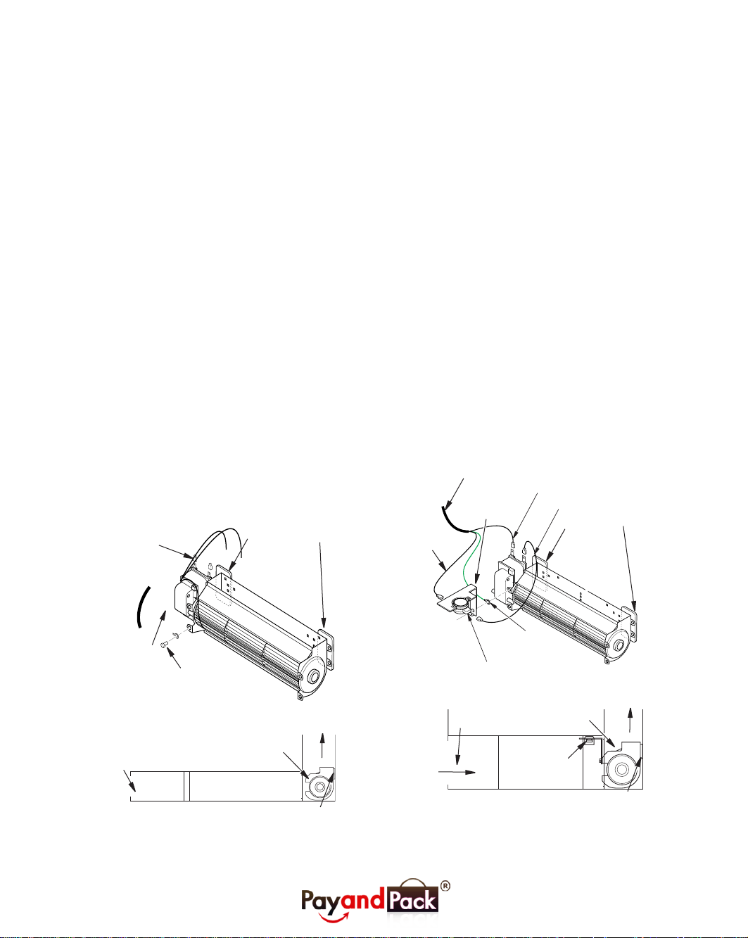
Attach the power cord to the blower 1.
motor by rmly pushing the two female
terminals at the end of the power cord
onto the two spade terminals on the
blower motor (see Figure 5).
Attach green ground wire from power 2.
cord to blower housing using screw
provided (see Figure 5) Tighten screws
securely with a phillips screwdriver.
Place the blower against the lower rear 3.
wall of the rebox outer wrapper with
the exhaust port directed upward. De-
pending on your model, you may have
to carefully route the blower assembly
past the controls and brackets, and
position the blower inside the back open-
ing. The blower will be held in position
against the back wall by the magnets
incorporated onto the blower housing
(see Figure 5).
Be certain that all wire terminals are 4.
securely attached to terminals on blower
motor and that the screw retaining the
green ground wire is tight.
Figure 5: Blower Model BK
Figure 6: Blower Model BKT
MODEL BK WIRE
ASSEMBLY
MODEL BKT WIRE
ASSEMBLY
Blower
Location
Blower Installed
After Lower Panel
Removed
Air Flow
Direction
Velcro strips
Green
Ground
Wire
Spade
Terminals
Screw
Velcro
Side view Firebox Bottom
Route BKT Blower
Through this Area
Ring
Therminal
on Green
Wire
Jumper Wire
To Blower
Motor Terminal
Thermal
Switch
Bracket
Thermal
Switch
To
Thermal
Switch
Blower
Location
Air Flow
Direction
Velcro strips
Power Cord
Velcro
Thermodisc
Side view Firebox Bottom
Note: The power cord outer insulation sleeve
may have to be stripped slightly to allow
enough wire length to reach and make all
connections. DO NOT trim excessive length
away. Just anable enough to make all con-
nections securely.
Page 4
Magnet
Loading ...
Loading ...