-1-
Installation Manual for Hydro
Smart Integrator and Zone Panels
Seemless Integration of Heating Source to Emitters
HSPS120LT
PHONE: 763-331-3066 EMAL: info@hydro-smart .com WEB: www.hydro-smart.com
-2-
WARNING!!
Do not plug in control cord until all uids are introduced and
thermostat connection(s) are nished.
DAMAGES - If unit is damaged, do not return to store. Please call 763-331-3066 for trouble shooting, returns, or
replacement parts.
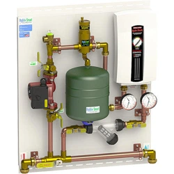
Step 1- Mount Integrator Panel onto wall with four 1/4” x 1 - 1/2” Lg wood screws. Utilize the slots
on the top and bottom of integrator panel and zone panel (When zoning by Pumps/Valves)
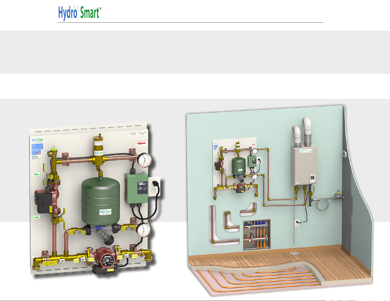
Step 2- Install Supply and Return lines to and from panel to boiler. Use Type L Copper or Oxygen Barrier PEX tubing.
Step 3- Install Supply and Return lines to and from panel to emitters (Manifold(s)). Connect integrator panel to zone
panel (When zoning by Pumps/Valves) Use Type L Copper or Oxygen Barrier PEX tubing.
Step 4- Introduce uids into system and purge air out of system.
Step 5- Install low voltage thermostat (TH135 or TH115-AF-024T)
Step 6- Plug in cord and activate thermostat. Acknowledge the following:
A. Both circulator pumps running.
B. Boiler energized and providing heat.
C. Observe gauges for performance of system (Pressure & Temperature).
-3-
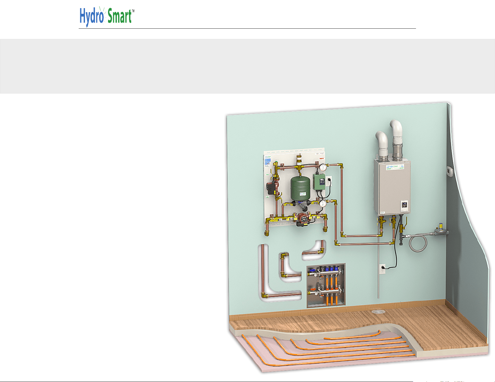
Filling The System
Overview of a typical System
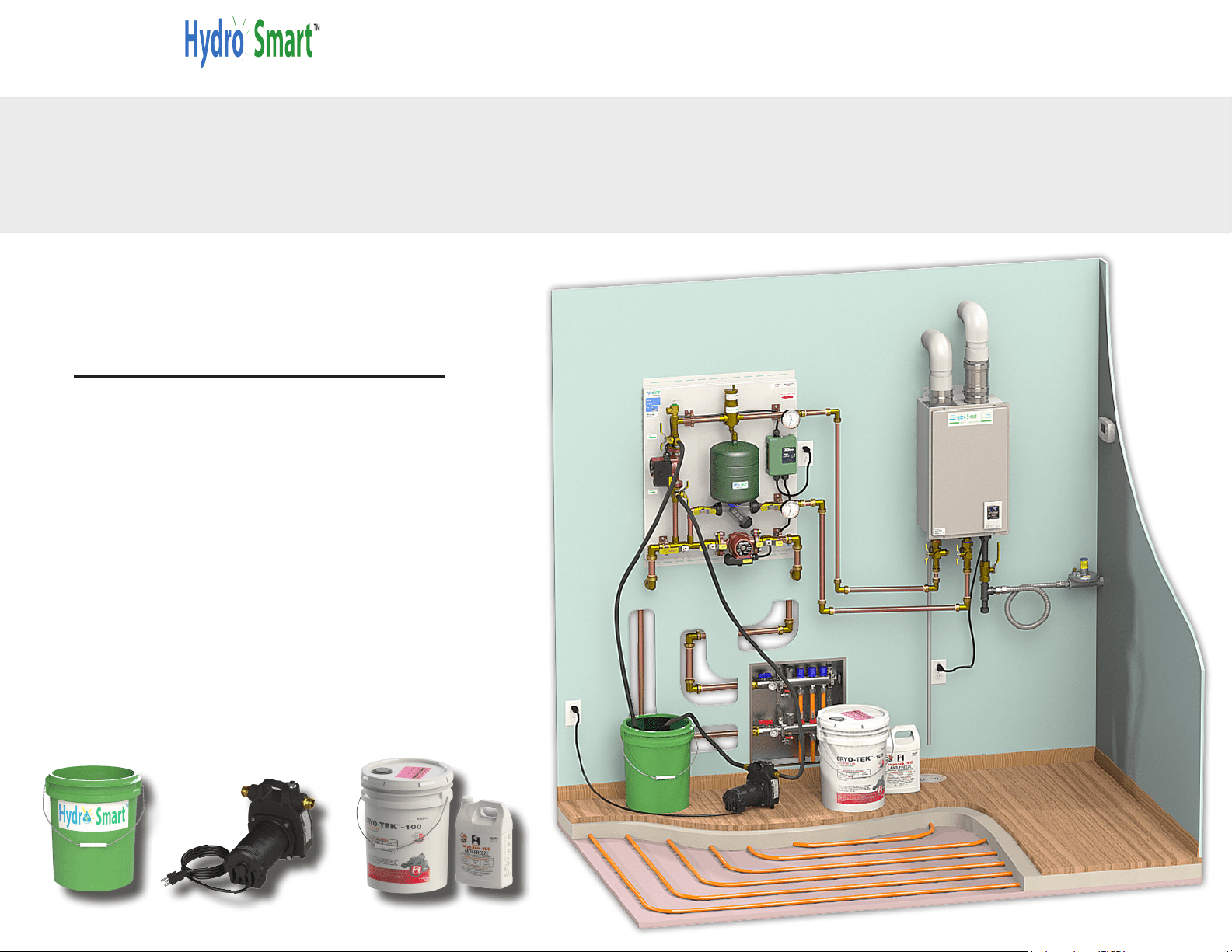
What you’ll need:
°1/2 HP Transfer Pump
°5-10 Gal. Bucket
°3 Washing Machine Hoses
°System Fluids (Distilled Water/
Propylene Glycol)
PHONE: 763-331-3066 EMAL: info@hydro-smart .com WEB: www.hydro-smart.com
-4-
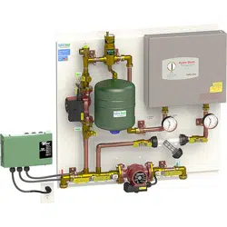
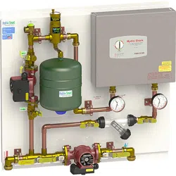
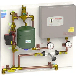
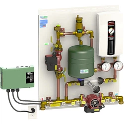
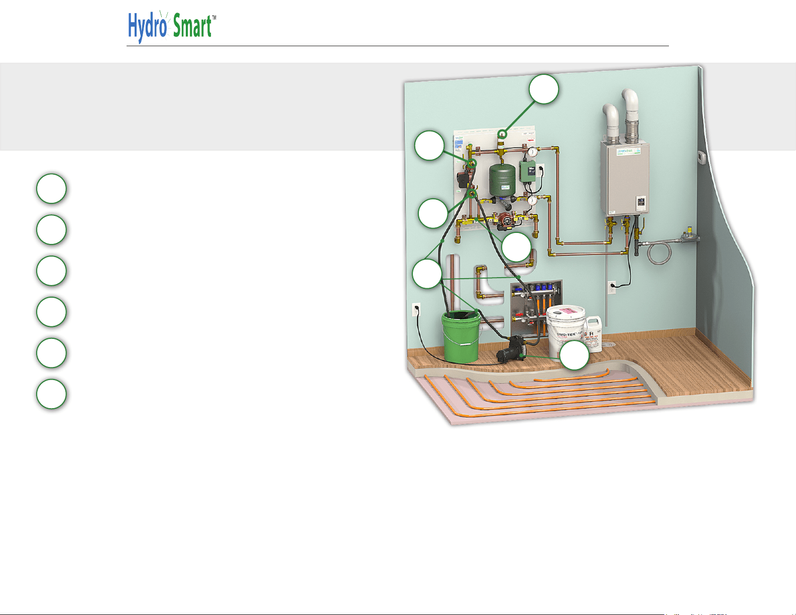
When lling the system you will use a “Fill Entry Point” (A) and a “Fill Exit Point” (B), 5-10 gallon bucket, 3 washing machine hoses (F) (6 Ft), 1/2 Hp
“Transfer Pump” (D) and system uids.
When lling, purge 1-loop at a time with the rest of the remaining loops closed. Use propylene glycol (not ethylene glycol - car antifreeze). Make sure
“Purge Tee” (C) is in vertical position. Close “Air Eliminator” (E) when purging and pressurizing. When purging one loop (2-3 minutes) at a time observe
bubbles in bucket dissipating for removal of air. When all loops are purged free of air it is time to pressurize. With Transfer Pump (D) running, close off
“Fill Exit Point” (B) valve, pressure will now rise. When pressure gauge shows 18-24 PSI close off “Fill Entry Point” (A). System is now purged and
pressurized. For boiler operation rotate “Purge Tee” (C) to horizontal position and rotate “Air Eliminator”(E) stem cap srew CCW 1 turn.
A
B
C
D
B
A
F
E
F
D
C
E
For more detailed information on lling the system, continue to next page.
Filling The System
Quick Start
Entry Fill
Exit Fill
Purge Tee
1/2 HP Transfer Pump
Air Eliminator
Hoses
-5-
Filling The System
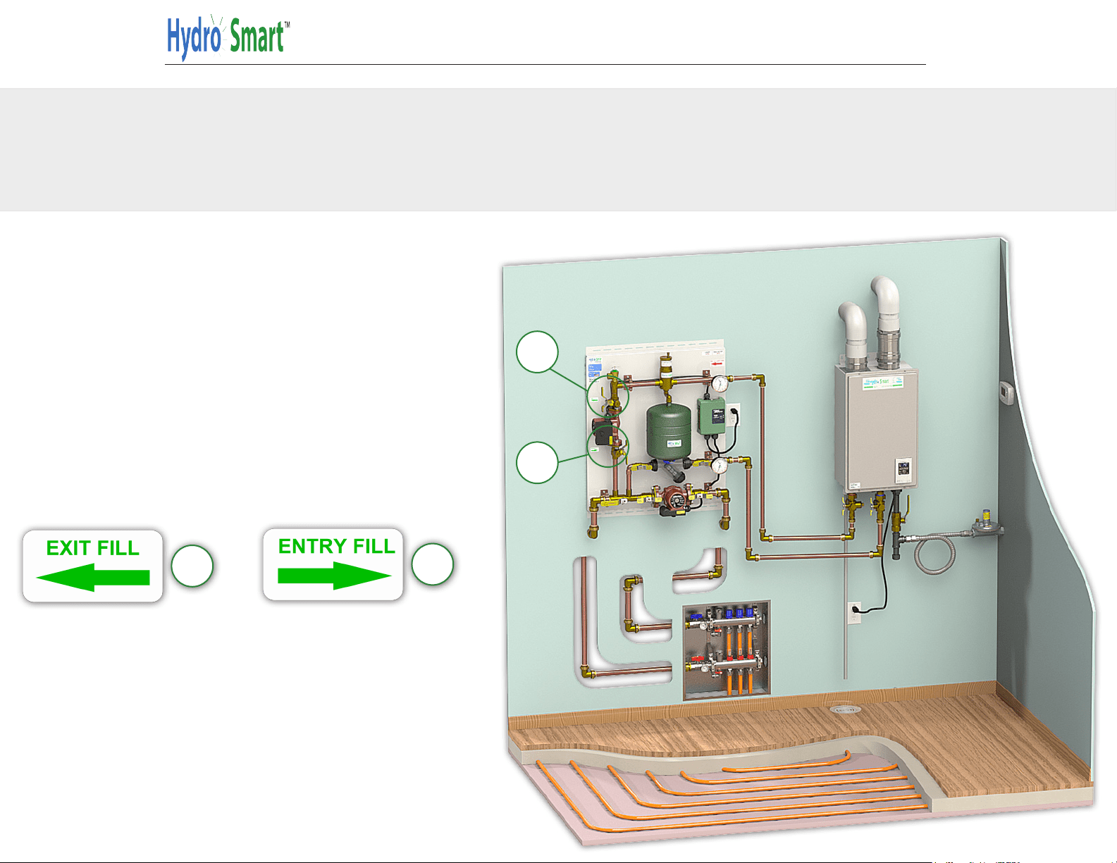
Entry Fill and Exit Fill
You will fill your system using
the entry and exit fill located on
the panel. Entry fill will be used
to pump water into the system.
Exit fill is where the water will
return back into your bucket.
A
B
A
B
PHONE: 763-331-3066 EMAL: info@hydro-smart .com WEB: www.hydro-smart.com
-6-
Filling The System
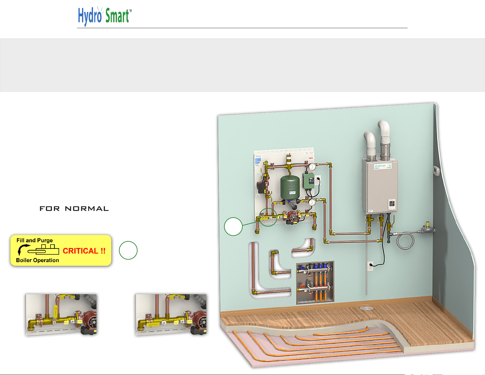
Purge Tee
When filling your system, The
purge tee handle should be in
the vertical position, once the
system is filled, purged, and
pressurized, you will return it
back to the horizontal position
for normal operation.
C
Filling System Normal Operation
C
-7-
Filling The System
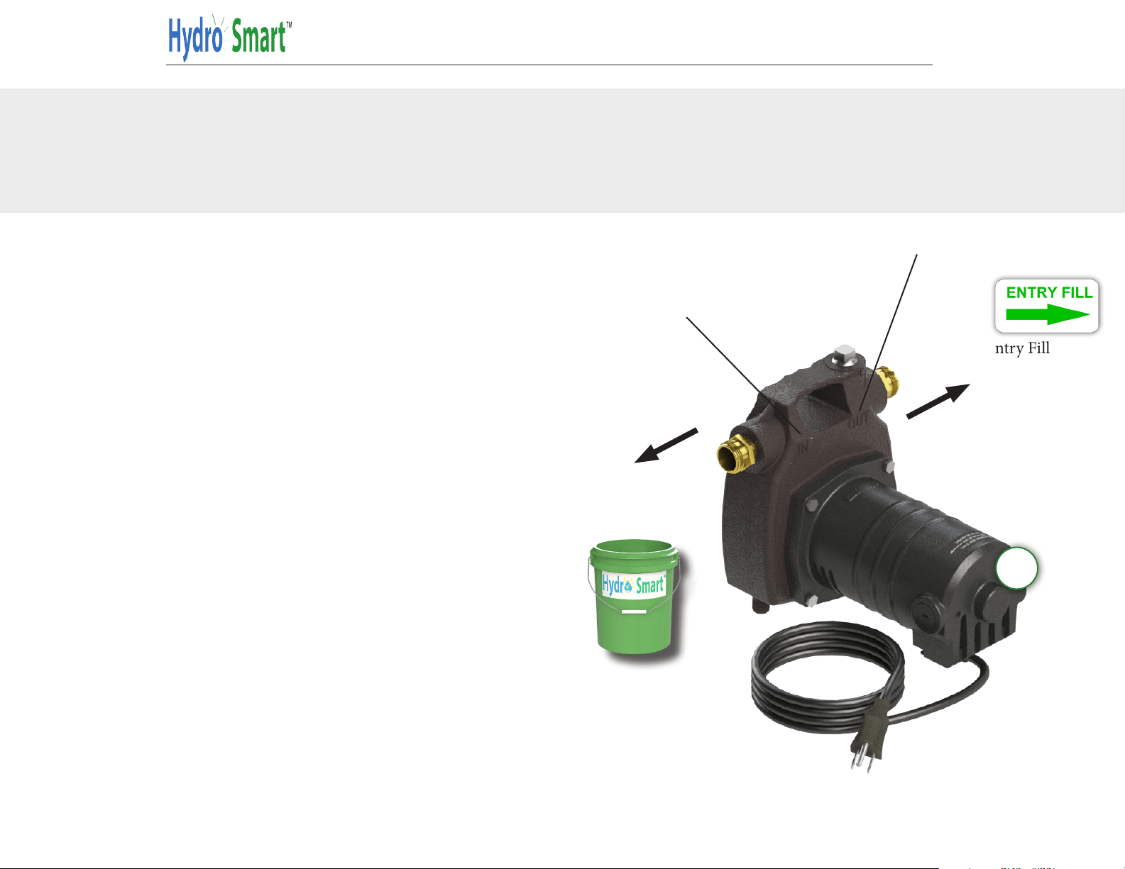
Transfer Pump and Hoses
Connect a hose from the “IN”
side of the transfer pump and
run it to your bucket. Connect
a hose from the “out” side of
the transer pump, and connect
it to the “Entry Fill” on the
panel. Connect a hose to the
“exit fill” on the panel and run
it back to your bucket.
Run To Bucket
Connect To Entry Fill
IN
OUT
D
PHONE: 763-331-3066 EMAL: info@hydro-smart .com WEB: www.hydro-smart.com
-8-
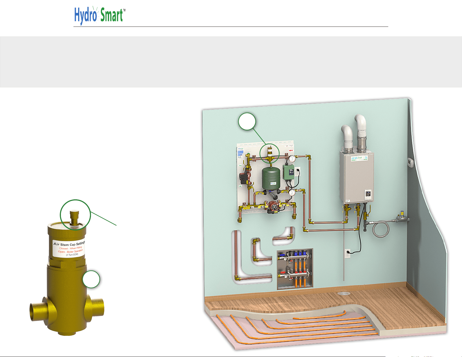
Filling The System
Air Eliminator
When filling your system, close
the air eliminator. Once your
system is filled, purged, and
pressurized, Open the air elim-
inator prior to operation by
twisting the Air stem cap one
turn counter clock wise.
E
Air stem cap
E
-9-
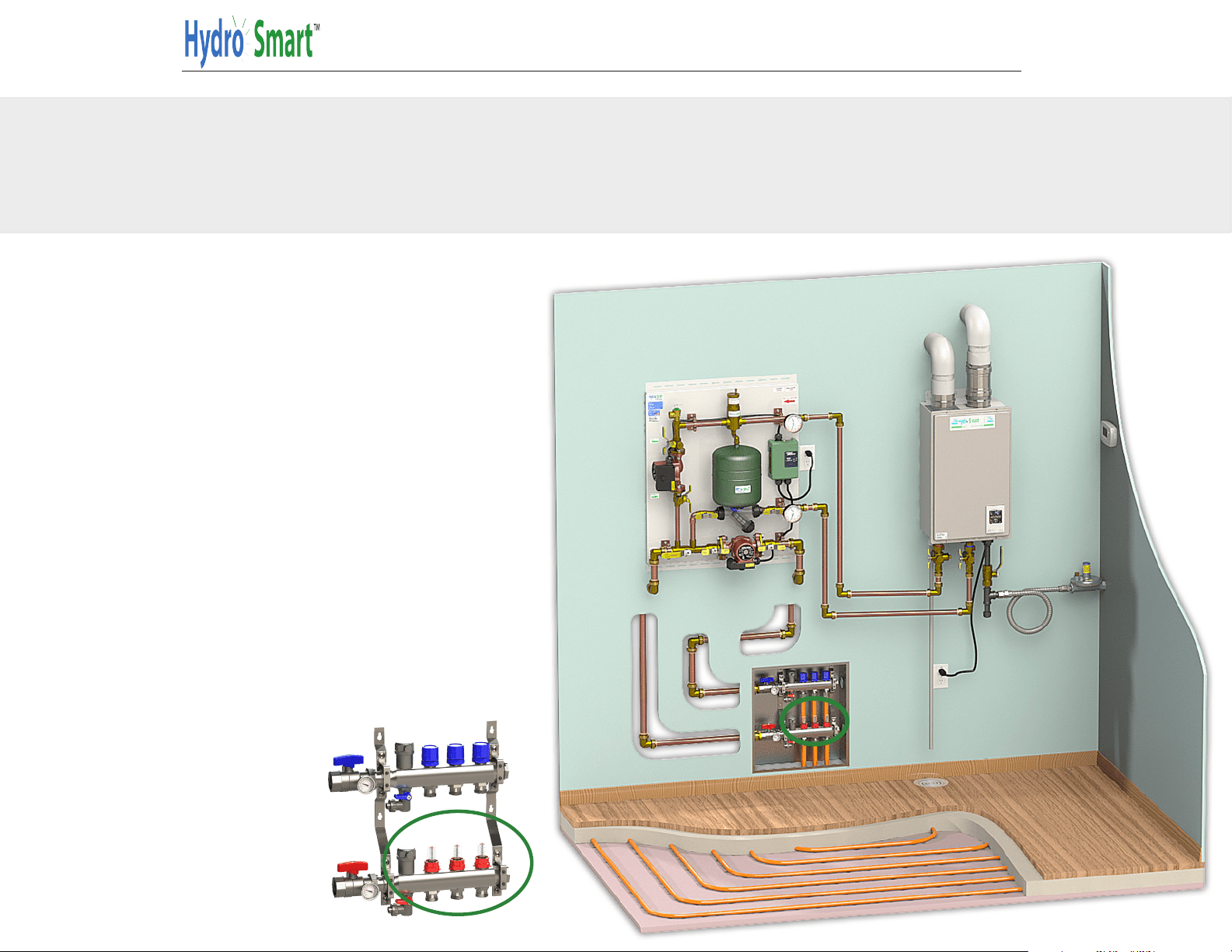
Filling The System
Manifold
When filling the system, fill
each loop individually. Close
All loops By Twisting the knobs
located on the manifold. Start
with the first loop by open-
ing it and purge all of the air
out. When the air is purged out,
close that loop and move on to
the next loop, repeating this
process until all loops have
been purged. Be sure to open
all of your loops once the sys-
tem is pressurized prior to run-
ning the system.
PHONE: 763-331-3066 EMAL: info@hydro-smart .com WEB: www.hydro-smart.com
-10-
Checking your system
Verify System is running correctly
Once your system has been
Filled, Purged, and Pressurized,
verify that both Primary and
Secondary pumps are running.
Check your supply and return
pressures. Your supply gauge
should be the same as what you
pressurized it to. You should see
about a 5-7 PSI differential on
the return gauge when the sys-
tem is running. Verify the boiler
is energized and providing heat.
Set your flow on the manifold.
Each loop should be at .5 to .75
GPM. (Based on 1/2” Pex Tubing)
Manifold/Emitter flow may vary depending
on Pex Size, length and other factors.