Hydro Shark Electric Boiler (07-36 KW)
Installation Manual and Owner’s Guide
If you have any questions,
please call or write to:
10725 165th Ave. NW
Elk River, MN 55331
Models:
SH-07 KW
SH-10 KW
SH-12 KW
SH-14 KW
SH-19 KW
SH-24 KW
SH-29 KW
SH-36 KW
Featuring
• Efciency: 100 %
• Wall Hung
• Flow Activated: .5 GPM
• Copper Heating Vessel
• Temperature Range: 86°-140° F*
• No Venting Required
• Modulation Status LED
The Hydro Shark Electric Boiler features advanced
technology, impressive energy-saving performance,
and a compact design. Exclusively manufactured by
Stiebel Eltron, a leader in heating technologies for the
past 80 years.
Do not return to stores.
Damages or repairs call
Hydro Smart 763-331-3066
M-F 8 AM - 5 PM Sat 8 AM - Noon
12-36 KW
07-10 KW
UL 834
UL 499

2
CONTENTS
Installation Manual
SPECIFICATIONS..........................................................................................................4
INTRODUCTION............................................................................................................5
MOUNTING THE UNIT...................................................................................................6
INSTALLATION...............................................................................................................7
Electrical Connections.........................................................................................7
Fluid connections.................................................................................................10
Technical Data.....................................................................................................10
Wiring Diagrams...................................................................................................11
APPLICATIONS..............................................................................................................12
OWNER’S GUIDE
TROUBLESHOOTING..................................................................................................15
General...............................................................................................................15
Components Diagram.........................................................................................16
PARTS LIST...................................................................................................................17
PRESSURE DROP TABLE............................................................................................18
IMPORTANT!
BOILERS ARE TO BE USED FOR RADIANT FLOOR HEATING ONLY!**
THIS MANUAL MUST BE READ CAREFULLY BEFORE ATTEMPTING TO INSTALL THE HYDRO
SHARK BOILERS. IF YOU DO NOT FOLLOW THE SAFETY RULES OR THE INSTRUCTIONS OUT-
LINED IN THIS MANUAL, THE UNIT MAY NOT OPERATE PROPERLY AND IT COULD CAUSE PROP-
ERTY DAMAGE, SERIOUS BODILY INJURY AND/OR DEATH.
MANUFACTURER WILL NOT BE LIABLE FOR ANY DAMAGES BECAUSE OF FAILURE TO COMPLY
WITH INSTALLATION AND OPERATING INSTRUCTIONS OUTLINED IN THIS MANUAL OR BE-
CAUSE OF IMPROPER USE. IMPROPER USE INCLUDES THE USE FOR THIS APPLIANCE TO HEAT
ANY LIQUID OTHER THAN WATER OR PROPYLENE GLYCOL. FAILURE TO COMPLY WITH THE
INSTALLATION AND OPERATING INSTRUCTIONS OR IMPROPER USE VOIDS THE WARRANTY.
NEVER REMOVE THE UNITS FRONT COVER UNLESS POWER IS TURNED OFF.
IF YOU HAVE ANY QUESTIONS REGARDING THE INSTALLATION OR OPERATION OF THESE BOILER,
PLEASE CALL OUR TECHNICAL SERVICE LINE AT 763-331-3066.
**Unless when used with Hydro Smart Combi Panel (Use SH-29 or SH-36 KW Boilers only with Combi Panel Systems, Size
boilers accordingly)

3
Installation Manual
CONGRATULATIONS
Congratulations and thank you for choosing our micro boiler. Before use, we
recommend that you read through this installation manual carefully. Keep
this manual for future reference.
If you need an additional manual, contact the manufacturer or your local
distributor. When you call, please tell us the product name and the serial
number of your unit written on the rating plate of the boiler.
4
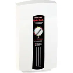
SPECIFICATIONS
HYDRO SHARK
MODEL KW VOLTS WIRE SIZE
AMP
DRAW
(MAX)
DBL POLE
BREAKER
SIZE
BTU
WATER
TEMP
RANGE
SH-07 7
240
8 30 (1) 40 24,573
86° - 140° F
SH-10 10 6 40 (1) 50 32,765
SH-12 12 4 50 (1) 70 40,956
SH-14 14 2 x 8 60 (2) 40 49,147
SH-19 19 2 x 6 80 (2) 50 65,526
SH-24 24 2 x 4 100 (2) 70 81,912
SH-29 29 3 x 6 120 (3) 50 98,977
SH-36 36 3 x 4 150 (3) 70 122,868
0
2
4
6
7
8
Boiler Flow-GPM
90 100 110 120 130
SH-XX
Boiler Temp vs Flow Rate with
70 Deg F Return Fluid
DEG F
1
3
5
140
SH-07
SH-10
SH-12
SH-14
SH-19
SH-24
SH-29
SH-36
____
____
____
____
____
____
____
____

5
INTRODUCTION
IMPORTANT!
GENERAL
Read this entire manual. Failure to follow all the guides, instructions and rules could cause personal
injury or property damage. Improper installation, adjustment, alteration, service and use of this unit
can result in serious injury.
This unit must be installed by a licensed electrician and plumber. The installation must comply with
all national, state and local plumbing and electric codes. Proper installation is the responsibility of the
installer. Failure to comply with the installation and operating instructions or improper use voids the
warranty.
Save these instructions for future reference. Installer should leave these instructions with the consum-
er.
If you have any questions regarding the installation, use or operation of this micro boiler, or if you
need any additional installation manuals call Hydro Smart at 763-331-3066 or visit us online at www.
hydro-smart.com
• The output of heat from the boiler is electronically controlled. The boiler will deliver any water tem-
perature between 86° F - 140° F. Set the desired water delivery temperature using the knob on the
front cover. (Do not exceed temperatures above 130° when using this product with tubing in
concrete)
• When the power light is ashing, full element power is being applied. When the power light is not
ashing, the element power is being modulated to the water delivery temperature.
• Recommend setting for radiant oor heating (Tubing in Concrete) is 105° F - 125° F.
• Recommended setting for Staple Up (Floor Warming Only) is 130° - 140° F.
• Temperature setting and water delivery temperatures may vary depending on ow rates. Size boil-
er accordingly. See ow rate chart for more information.

6
MOUNTING THE UNIT
UNIT MUST BE INSTALLED IN A VERTICAL POSITION WITH THE WA-
TER FITTINGS POINTING DOWNWARD. DO NOT INSTALL UNIT WHERE
IT WOULD ROUTINELY BE SPLASHED WITH WATER OR ELECTRICAL
SHOCK MAY RESULT.
1. Leave a minimum of 5” clearance on all sides for servicing.
2. Make sure the power is off.
3. Remove the cover.
4. Mount securely to wall by putting screws through mounting holes.
5. Screws and plastic wall anchors for mounting are provided.
ED F
G
A
B
C
2
1
3
A
Dimensions
B
C
D
E
F
G
3
/
16
7
ELECTRICAL CONNECTIONS
1. All electrical work must comply with the national, state, local & any other applicable codes.
2. The boiler should be connected to properly grounded dedicated branch circuits of proper
voltage rating. Ground must be brought to the ‘Ground’ at the circuit breaker panel.
3. SH-12 can be connected to ONE independent circuit.
4. A SH-14, SH-19 & SH-24 can be connected to TWO independent circuits Use supply table.
Protected by TWO double pole breakers sized for the load.
5. A SH-29 and SH-36, can be connected to THREE independent circuits. Use supply cable
protected by THREE double pole breakers sized for the load.
6. Cut the electrical connection cable to length and strip.
7. The wire must be fed through the knockouts located between the Supply and Return uid con-
nections. The “Live” wires must be connected to the slots on the terminal block marked “L” and
“L”. The ground wire must be connected to slot marked with the ground symbol.
8. Reinstall the cover screws.
WARNING! As with any electrical appliance, failure to electrically ground may result in serious injury or Death.
WARNING: BEFORE BEGINNING ANY WORK ON THE ELECTRIC INSTAL-
LATION, BE SURE THAT THE MAIN BREAKER PANEL SWITCHES ARE
“OFF” TO AVOID ANY DANGER OF ELECTRIC SHOCK. ALL MOUNTING
AND PLUMBING MUST BE COMPLETED BEFORE PROCEEDING WITH
ELECTRICAL HOOK-UP. WHERE REQUIRED BY LOCAL,STATE OR NA-
TIONAL ELECTRICAL CODES THE CIRCUITS SHOULD BE EQUIPPED
WITH A “ GROUND FAULT INTERRUPTER”.
INSTALLATION
8
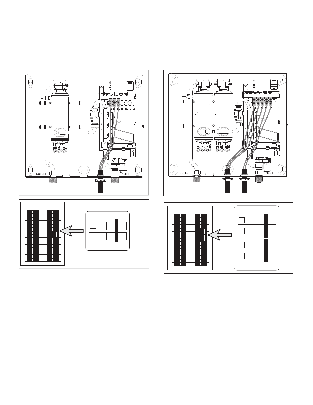
ELECTRICAL CONNECTIONS CONT’D
SH-12 SH-14, SH-19, SH-24
FFO
NO
FFO
NO
CKT 1
FFO
NO
FFO
NO
FFO
NO
FFO
NO
CKT 1
CKT 2
9
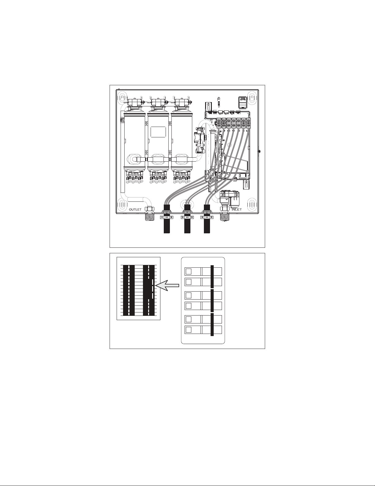
SH-29, SH-36
ELECTRICAL CONNECTIONS CONT’D
FFO
NO
FFO
NO
FFO
NO
FFO
NO
FFO
NO
FFO
NO
CKT 1
CKT 2
CKT 3
Please refer to specication table for wiring and circuit breaker size. See technical data section for
wiring diagrams.
CIRCUIT CONNECTION

10
FLUID CONNECTIONS
NOTE: EXCESSIVE HEAT FROM SOLDERING COPPER PIPES NEAR THE BOILER MAY CAUSE DAMAGE.
1. All plumbing work must comply with the national, state, local & any other applicable codes.
2. Make sure the radiant oor system has been purged & is free of oating debris.
3. The return side (inlet) is on the right side of the unit, the supply side (outlet) is on the left of
the unit.
4. A pressure & temperature relief valve should be installed on the hot water supply side (out-
let) of the unit. (Hydro Smart Pre-Plumbed Panels include pressure relief valve)
5. The boiler is designed for a connection to copper tubing and/or PEX tubing. If soldering the unit
is necessary, please direct the ame away from the housing of the unit to avoid damage.
6. When all plumbing work is completed, check for leaks & take corrective action before pro-
ceeding.
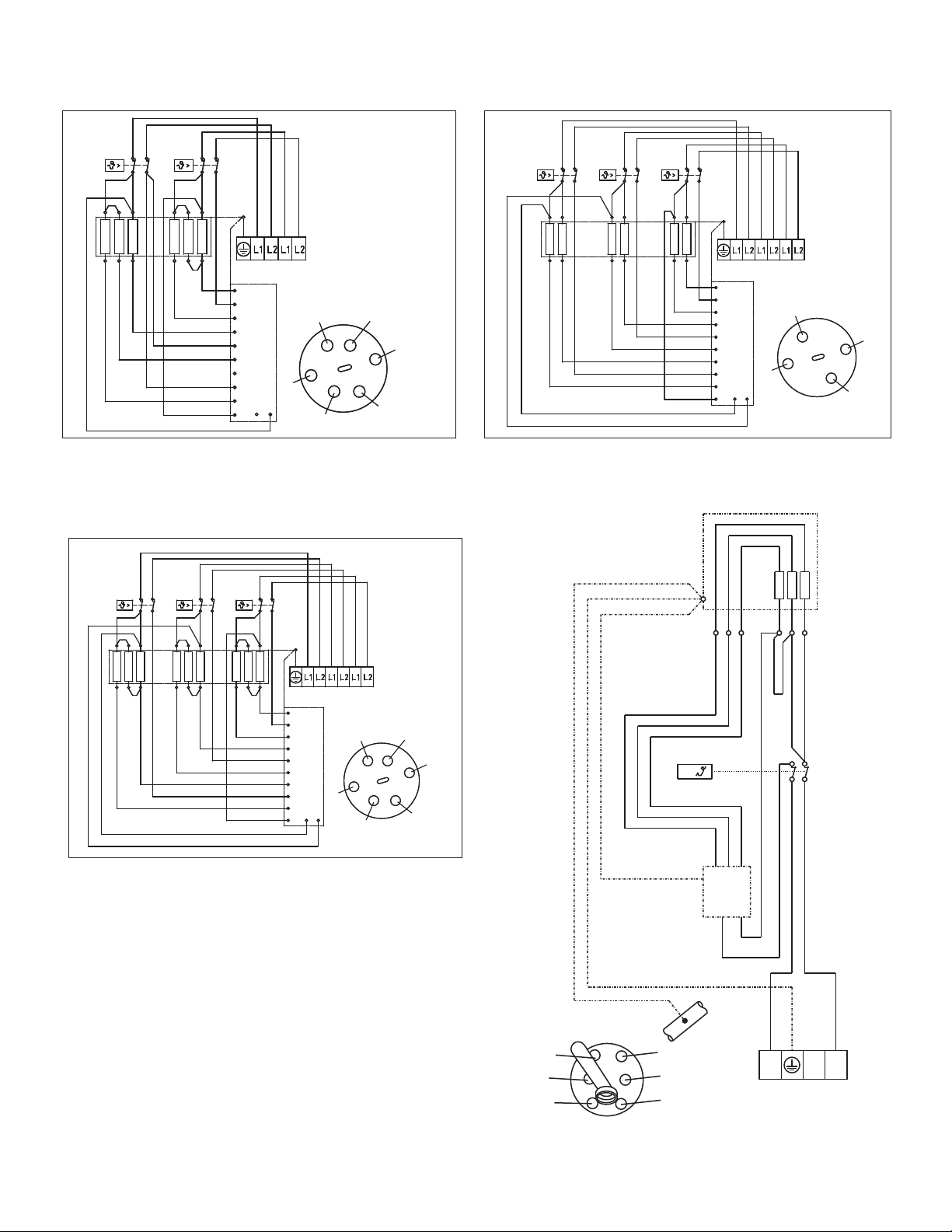
TECHNICAL DATA
WIRING DIAGRAMS
CKT 1
6 4 2
5 3 1
6
5
4
9/10
11/12
3
2
7/8
1
13
6
4
2
5
3
1
14 15
SH-12
SH-12 SH-14, SH-19
24
5 1
4 2
CKT 1
CKT 2
5 1
6
5
4
11/12
9/10
3
2
7/8
1
13
4
2
5
1
14 15
SH-14, SH-19
11
Note:
1. Boilers are considered a continuous load.
2. Copper conductors only.
WIRING DIAGRAMS
SH-24
6 4 2
5 3
CKT 1
CKT 2
1
6 4 2
5 3 1
6
5
4
11/12
9/10
3
2
7/8
1
13
6
4
2
5
3
1
14 15
SH-24
SH-29
SH-36
4 2
5 1
4 2
15
4 2
CKT 1
CKT 2
CKT 3
15
6
5
4
11/12
9/10
3
2
7/8
1
13
4
2
5
1
14 15
SH-29
46 2
35 1
46
CKT 1
CKT 2
CKT 3
2
5 3 1
6 4 2
5 3 1
6
4
2
5
3
1
6
5
4
11/12
9/10
3
2
7/8
1
13
14 15
SH-36
>
L
L
1
2
3
4
56
21
3
4
5 6
SH-07 / 10 KW
12
APPLICATIONS
Space Heating Applications
• In order to purge air in water pipes within a closed loop system, an air vent,
air separator, and expansion tank should be installed in the system. (Hydro
Smart pre-built space heating panels incorporate all of these features).
• Water temperature over 125° F (52° C) can cause sever burns instantly of
death from scalding.
• Chemicals such as diluted Glycol can be used for radiant oor, Hydro/fan
coil air or Baseboard heating only. The diluted solution of glycol must contain
between 25% and 55% of Glycol. Be aware that in a closed loop system, low
pressure in the heat exchanger can cause low-temperature boiling, resulting
in excessive noise and damage to the micro boiler. Consult with the glycol
maker for specications prior to use.
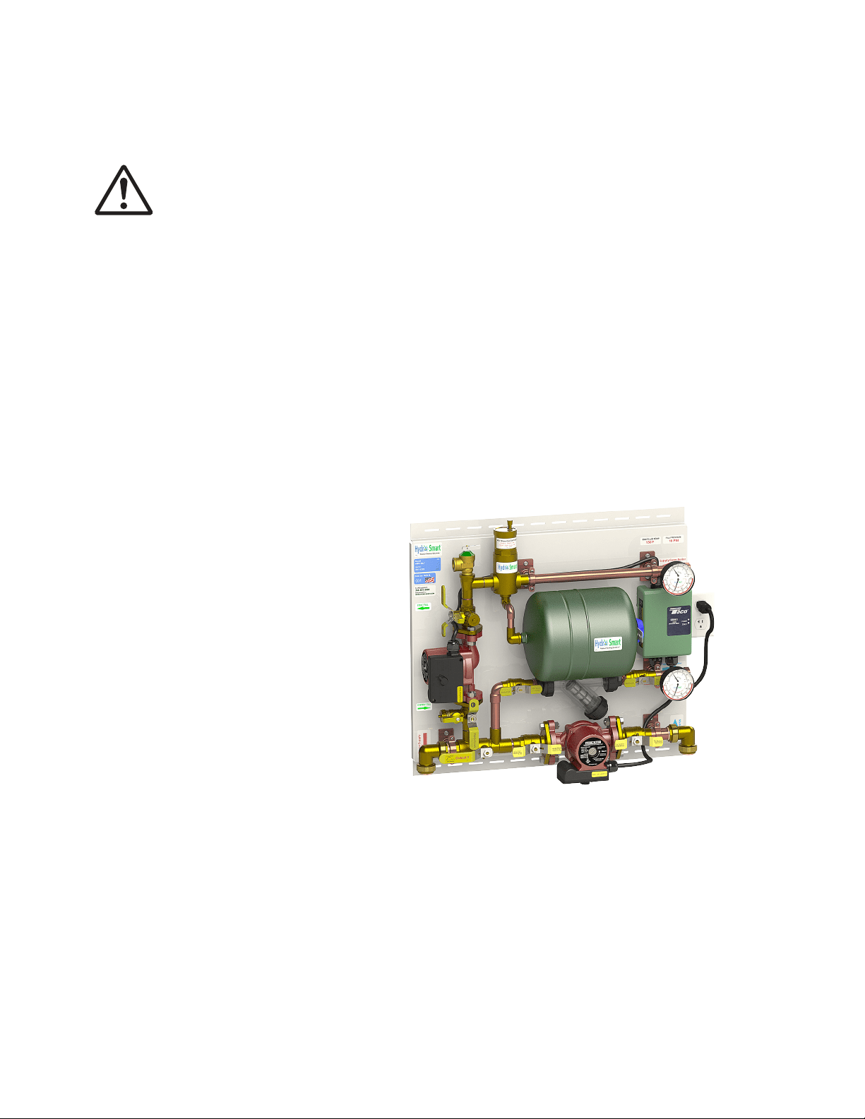
Hydro Smart Pre-Built Space Heating Panels
Hydro Smart per-plumbed panels help make space heating easy and reliable. These panels are
professionally engineered and use proven Primary/Secondary hydronic practices. Call Tech Support
(1-763-331-3066) for assistance.
HSPS120LT 1 Zone Panel:
For more information on Hydro Smart pre-plumbed panels and zoning options for this boiler please
visit www.hydro-smart.com or call 763-331-3066.
Sample:
WARNING

13
Dual-purpose hot water heating
(Domestic and Space Heating)
Insert a Hydro Smart Combi Panel to provide potable heated water and Hydronic Heating (with space
heating panel(s)) with one heat source.
The Hydro Smart Combi Panel integrates with a wide variety of boilers and delivers “Priority” potable
heated water with no storage tank and hydronic space heating in a small reliable package.
Follow all local codes, or in the absence of local codes, follow the most recent
edition of the National Standard Code, ANSI Z21.10.3.
For more information on Hydro Smart Combi panels and integrating space heating and domestic wa-
ter for this boiler please visit www.hydro-smart.com or call 763-331-3066.
NOTICE
Use Combi Panel with SH-29 or SH-36 KW Boilers Only. Size boiler for domestic
and radiant applications accordingly.
NOTICE

14
Owner’s Guide
CONGRATULATIONS
Congratulations and thank you for choosing our micro boiler. Before
use, we recommend that you read through this owner’s guide carefully.
Keep this manual for future reference.
If you need an additional manual, contact the manufacturer or your local
distributor. When you call, please tell us the product name and the serial
number of your unit written on the rating plate of the boiler.

15
TROUBLESHOOTING
General
Symptom Possible Cause Solution
No Hot Water •No Power
•Safety ermal Cut O Tripped
•Not Enough Flow Rate To Activate
•Plugged Flow Sensor
•Utility Controlling Load
•Reset ermal Cut O
•Wrong Size Pump
•Activate ermostat/
Clean Flow Sensor
Water Not Hot Enough •Water Flow Too High
•Voltage To Low
•Glycol/Water Ratio Too High
•Manifold or Ball Valve Closed
•Reduce Water Flow Rate
•Supply Correct Voltage to Unit
•More than 20%, less than 50%
•Open Loops/Ball Valves
LEDs Do Not Light •Problem With Electronic Controls Call Tech Support at 763-331-3066

16
A
A- Fluid Temp.Controller
B- High Limit Safety
C- Flow Meter
D- Wiring Terminal
E- Control Board
F- Cold Fluid Return - 3/4” MPT
G- Electrical Circuit Knock-Outs
H- Hot Fluid Supply - 3/4” MPT
I- Hinged Cover on 12- 36 KW Units
F
H
G
E
D
I
C
B
COMPONENTS DIAGRAM

17
PARTS LIST
Part Number Description
286356 Housing, SH-12 thru SH-36
245307 Temperature Control Knob, SH-07 thru SH-36
279998 Wiring Block, SH-07- thru SH-12
279997 Wiring Block, SH-14- thru SH-24
279996 Wiring Block, SH-29- thru SH-36
286360 Heating System, SH-12
286361 Heating System, SH-14
286362 Heating System, SH-19
286364 Heating System, SH-24
286373 Heating System, SH-29
286374 Heating System, SH-36
286369 High Limit, SH-07 thru SH-36
286366 Electronic Control Device Board, SH-12
286844 Electronic Control Device Board, SH-14 thru SH-19
286367 Electronic Control Device Board, SH-24
296888 Electronic Control Device Board, SH-29
296889 Electronic Control Device Board, SH-36
286461 Flow Sensor, SH-07 thru SH-36
278698 Plumbing Connection, S-R 3/4” NPT
286359 Electronic Temp Control, SH-07 thru SH-36
280677 Outlet Temperature Sensor, SH-07 thru SH-36
280730 Set Point Knob Board, SH-12 thru SH-36
292575 Housing, SH-07 thru SH-10
291851 Electronic Control Device Board, SH-07 thru SH-10
283455 Code Plug, SH-07 thru SH-10
292578 Back Panel, SH-07 thru SH-10
291699 Return Fluid Connection, SH-07 thru SH-10
278634 Supply Fluid Connection, SH-07 thru SH-10
292577 Cover, SH-07 thru SH-10
254312 Axis Connection Plug, SH-07 thru SH-10
18
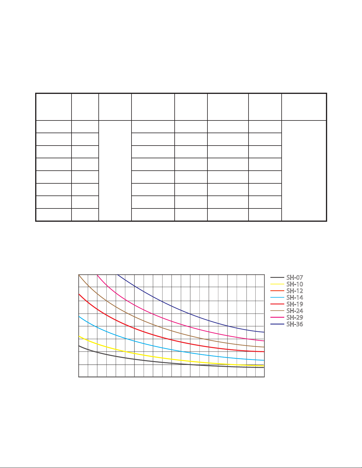
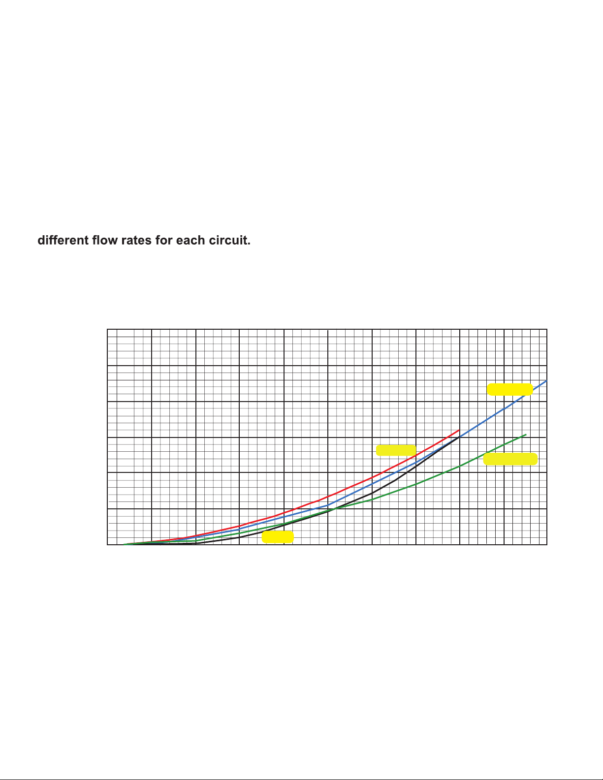
Boiler Pressure Drops Table
(Boilers SH-12 thru SH-36)
This table is used for sizing Primary (Boiler) Circulator
69
All boilers must use Primary/Secondary circuitry. This is used to create Hydraulic
seperation between the Boiler and Emitter circulators allowing you to create
Flow Pressure
(PSI)
FLOW GPM
0 .5 1 1.5 2 2.5 3 3.5 4 4.5 5
11.5
23
34.5
46
57.5
0
0
5
10
15
20
25
30
Flow Pressure
(HD Feet)
SH-7,10
SH-29,36
SH-12
SH-14,19,24

19
NOTES: