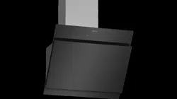
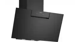
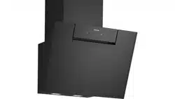
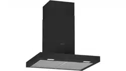
Owner Manual Extractor hood
Operating modes
Exhaust air mode
The air which is drawn in is cleaned by the grease filters and conveyed to the exterior by a pipe system.
Note: The exhaust air must not be conveyed into a functioning smoke or exhaust gas flue or into a shaft which is used to ventilate installation rooms which contain heat-producing appliances.
- Before conveying the exhaust air into a nonfunctioning smoke or exhaust gas flue, obtain the consent of the heating engineer responsible.
- If the exhaust air is conveyed through the outer wall, a telescopic wall box should be used.
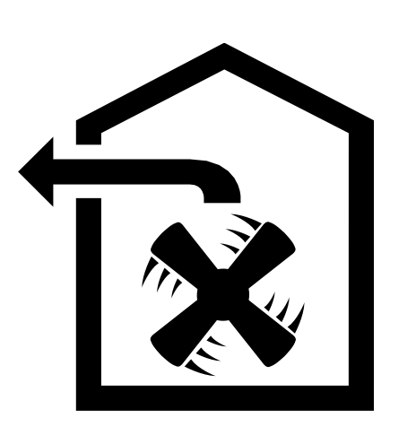
Circulating-air mode

The air which is drawn in is cleaned by the grease filters and an activated carbon filter and conveyed back into the kitchen.
Note: To bind odours in circulating-air mode, you must install an activated carbon filter. The different options for operating the appliance in circulating-air mode can be found in the brochure. Alternatively, ask your dealer. The required accessories are available from specialist retailers, from customer service or from the Online Shop.
Operating the appliance
These instructions apply to several appliance variants. It is possible that individual features are described which do not apply to your appliance.
Note: Switch on the extractor hood when you start cooking and switch it off again several minutes after you have finished cooking. This is the most effective way of removing the kitchen fumes.
Control panel

Setting the fan
Switching on
Touch the  symbol.
The fan starts at fan setting 2.
Selecting the fan setting
Touch symbol 1, 2 or 3 to set a different fan setting.
Switching off
Touch the symbol.
Intensive setting
You can use the intensive setting if there is a large build-up of odours and fumes/vapours.
Switching on
Touch the  symbol.
Note: After approx. 6 minutes, the extractor hood automatically switches back to fan setting 3.
Switching off
If you want to end intensive mode before the preset time expires, touch the symbol.
Intermediate position for the glass front
On some appliances, the glass front can be adjusted to an intermediate position. The intermediate position can be used for eliminating particularly strong cooking smells and large amounts of steam.
Take hold of the glass front in the centre and open it carefully.
Lighting
The lighting can be switched on and off independently of the fan.
Touch the  symbol.
Installation
Preparing for installation
Caution! Ensure that there are no electrical wires, gas pipes or water pipes in the area where holes are to be drilled.
If the extractor hood is to be operated in exhaust-air mode, a flue duct must be fitted.
If the extractor hood is to be operated in air-recirculation mode, an optional accessory must be fitted. To do this, refer to the installation instructions provided. The flue duct does not need to be fitted for air-recirculation mode.
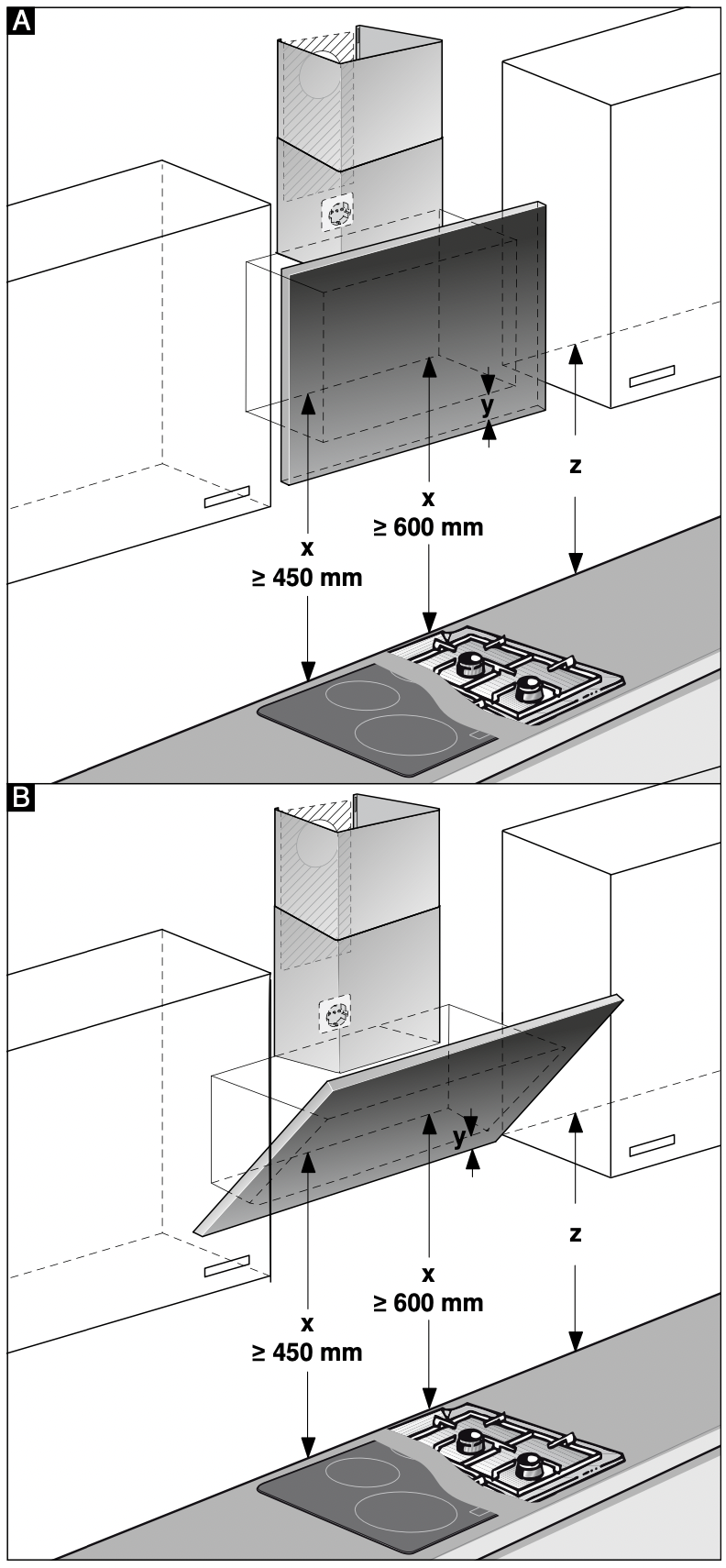
- Determine where the extractor hood should be positioned and lightly mark where the lower edge of the appliance should be on the wall. Determine where the middle should be based on the hob.
Note: We recommend fitting the extractor hood such that the lower edge of the glass screen is in line with the lower edges of the adjacent wall-hung cabinets. Make sure that the specified safety clearances from the hob are complied with.
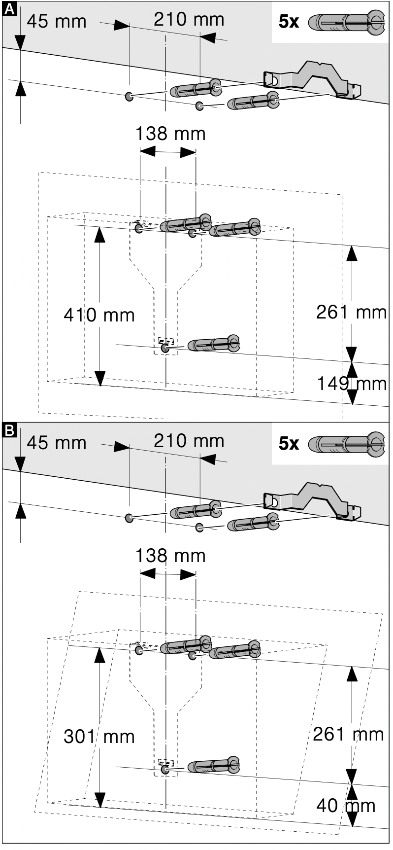
- Place the template against the line drawn on the wall and fasten it in place. Mark where the screws should be inserted.
To fit the flue duct, the template must be cut along the marked cut line.
- Drill 8 mm diameter holes to a depth of 80 mm for fastening the appliance, remove the template and press in the wall plugs flush with the wall.
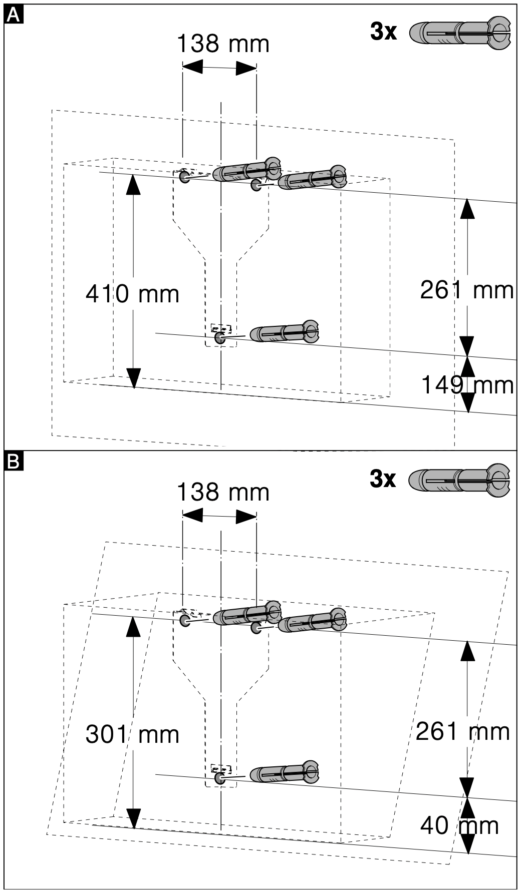
Fitting with a flue duct
Fitting without a flue duct
Installation
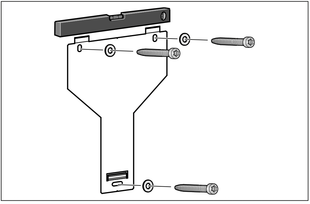
Screw in the mounting supports for the extractor hood until they are hand-tight, use a spirit level to level the appliance and then screw the mounting supports in fully.
Wall-mounting the appliance and levelling it
- First remove the protective film from the back of the appliance and, following installation, remove the rest of the film.
- When mounting the appliance, ensure that it engages properly with the mounting supports.
- If required, the appliance can be moved to the right or to the left.
- Firmly tighten the screws for the mounting supports.
Hold the bracket firmly when doing so. A
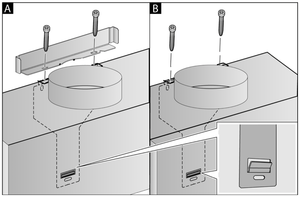
- If no duct is to be fitted, screw in the two locking screws without the bracket. B
Connecting the pipes
If the extractor hood is to be operated in exhaust-air mode, the pipes must be connected. If the extractor hood is to be operated in air-recirculation mode, an optional accessory must be fitted. To do this, refer to the installation instructions provided.
Note: If an aluminium pipe is being used, smooth the connection area beforehand.
Exhaust air pipe, dia. 150 mm (recommended size)
Fit the exhaust air pipe directly to the air-pipe connector and seal the joint.
Exhaust air pipe, dia. 120 mm
- Fit the reducing connector directly to the air-pipe connector.
- Attach the exhaust air pipe to the reducing connector.
- Use suitable means to seal both joints.
Attaching the flue duct
If the extractor hood is to be operated in exhaust-air mode, a flue duct must be fitted.
The flue duct does not need to be fitted for airrecirculation mode.
Warning - Risk of injury! From sharp edges during installation. Always wear protective gloves while installing the appliance.
Warning - Risk of electric shock! Components inside the appliance may have sharp edges. These may damage the connecting cable. Do not kink or pinch the connecting cable during installation.
- Separate the flue duct sections by removing the adhesive tape.
- Remove the pieces of protective film from both flue duct sections.
- Push one flue duct section into the other.
Notes
To prevent scratches, lay paper over the edges of the outer flue duct section to protect the surface.
The slots of the inner flue duct section point downwards.
- Place flue ducts sections on the appliance.
- Slide the inner flue duct section upwards, attach it to the left and right sides of the retaining bracket, and then slide it down to engage it. A
- Screw the flue duct section to the sides of the retaining bracket using two screws. B
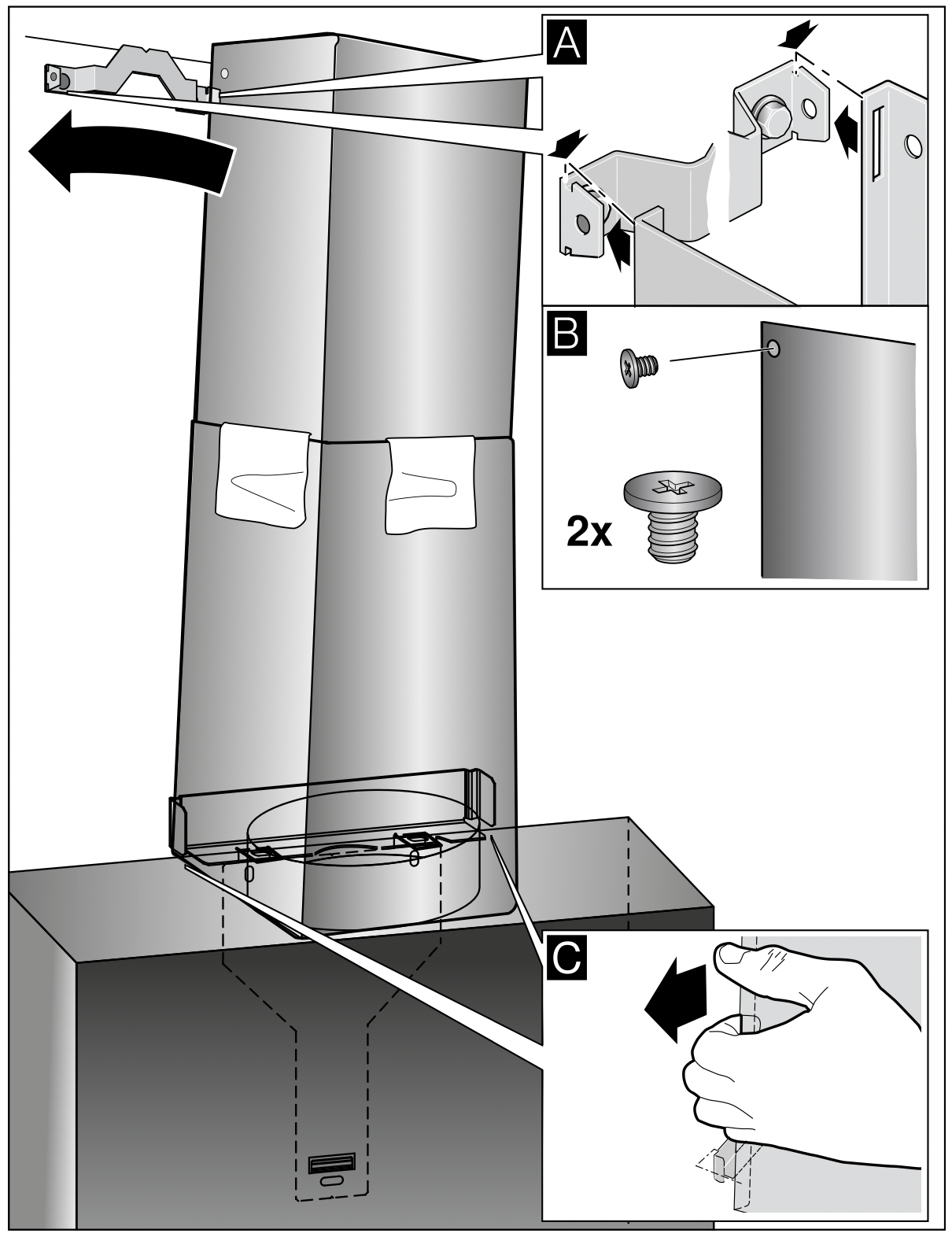
- Clip the lower flue duct section in at the retaining bracket. The connection cable must not be damaged. C
Note: If an air-recirculation optional accessory has been fitted and the extractor hood is to be operated without a flue duct, the cable must be wound onto the connector.
Cleaning and maintenance
Warning - Risk of burns! The appliance becomes hot during operation. Allow the appliance to cool down before cleaning.
Warning - Risk of electric shock! Penetrating moisture may result in an electric shock. Clean the appliance using a damp cloth only. Before cleaning, pull out the mains plug or switch off the circuit breaker in the fuse box.
Warning - Risk of electric shock! Do not use any high-pressure cleaners or steam cleaners, which can result in an electric shock.
Warning - Risk of injury! Components inside the appliance may have sharp edges. Wear protective gloves.
Warning - Risk of injury! Risk of trapping body parts when opening and closing the glass front. Do not reach into the area behind the glass panel, and keep your fingers away from the hinges.
Cleaning agents
To ensure that the different surfaces are not damaged by using the wrong cleaning product, follow the instructions in the table. Do not use any of the following:
- Harsh or abrasive cleaning agents, e.g. scouring powder or liquid scouring cleaner,
- Cleaning products with a high alcohol content,
- Hard scouring pads or cleaning sponges,
- Pressure washers or steam cleaners,
- Cleaning products that dissolve limescale,
- Aggressive all-purpose cleaning products,
- Oven spray.
Note: Wash new sponge cloths thoroughly before use.
Note: Follow all instructions and warnings included with the cleaning products.
| Area |
Cleaning products
|
| Stainless steel |
Hot soapy water:
Clean with a dish cloth and then dry with a soft cloth.
Clean stainless steel surfaces in the direction of the grain only.
Special stainless steel cleaning products are available from our after-sales service or from specialist retailers.Apply a very thin layer of the cleaning product with a soft cloth.
|
| Painted surfaces |
Hot soapy water:
Clean using a damp dish cloth and then dry with a soft cloth.
Do not use stainless steel cleaner.
|
| Aluminium and plastic |
Hot soapy water:
Clean with a soft cloth.
|
| Glass |
Glass cleaner:
Clean with a soft cloth. Do not use a glass scraper.
|
| Controls |
Hot soapy water:
Clean using a damp dish cloth and then dry with a soft cloth.
Risk of electric shock caused by penetrating moisture.
Risk of damage to the electronics caused by penetrating moisture. Never clean controls with a wet cloth.
Do not use stainless steel cleaner.
|
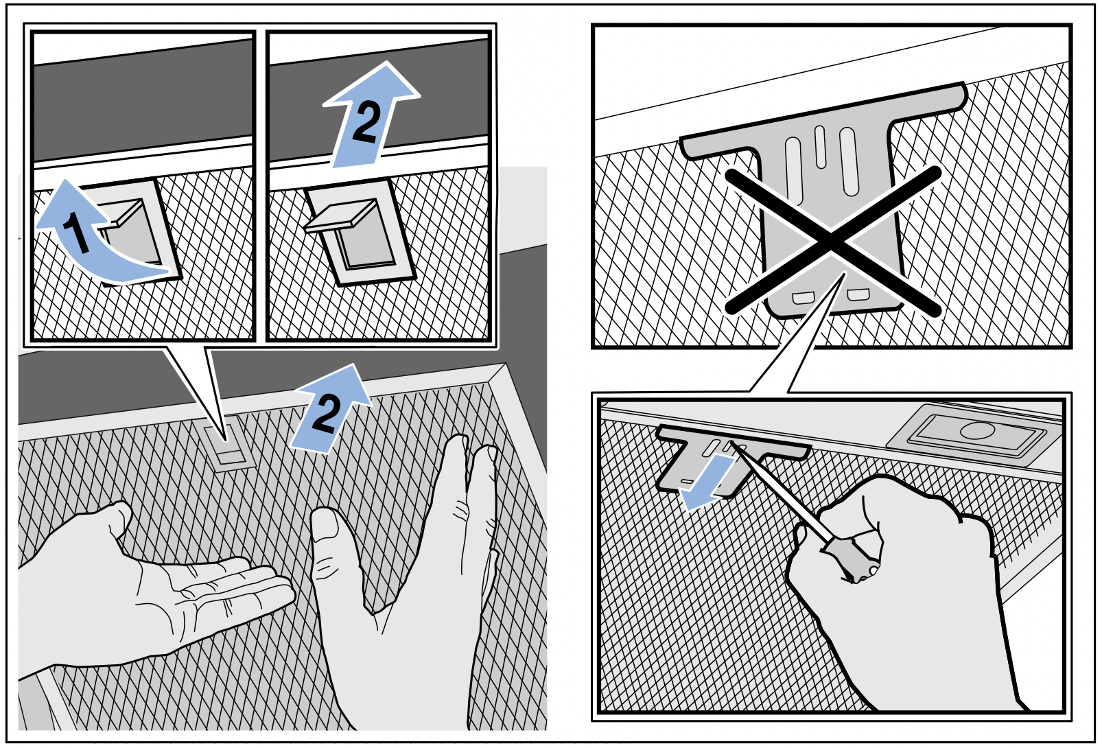
Removing metal grease filter
- Open the glass front slowly and fully. Hold the glass front in the centre when doing so, gripping it firmly.
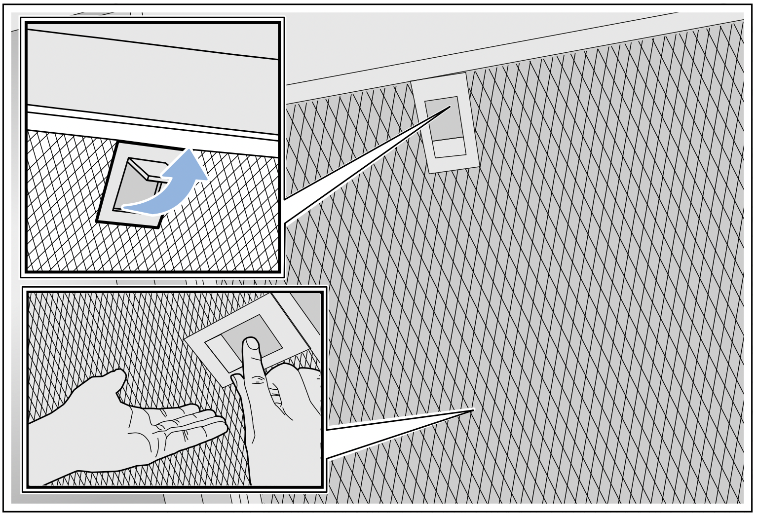
- Open the lock and swing down the metal grease filter. When you do this, take hold of the metal grease filter from underneath with your other hand.
- Take the metal grease filter out of the holder.
Notes
- Fat may accumulate in the bottom of the metal grease filter.
- Hold the metal grease filter level to prevent grease from dripping out.
Cleaning the metal mesh grease filters
These instructions apply to several appliance variants. It is possible that individual features are described which do not apply to your appliance.
Warning - Risk of fire! Fatty deposits in the grease filter may catch fire. Regularly clean the grease filter. Never operate the appliance without a grease filter.
Notes
- Do not use aggressive, acidic or alkaline cleaning products.
- We recommend cleaning the grease filters every 2 months.
- When cleaning the metal grease filters, also clean the metal grease filter holder in the appliance using a damp cloth.
- The metal grease filters can be cleaned in the dishwasher or by hand.
By hand:
Note: You can use a special degreaser to remove stubborn dirt. This can be ordered from the online shop.
- Soak the metal grease filters in hot soapy water.
- Clean the filters with a brush and then rinse them thoroughly.
- Leave the metal grease filters to drain on an absorbent material.
In the dishwasher:
Note: Slight discolouration may occur if the metal grease filters are cleaned in the dishwasher. This discolouration has no effect on the performance of the metal grease filters.
- Use normal domestic dishwashing detergents.
- Do not clean heavily soiled metal grease filters together with cookware.
- Place the metal grease filters in the dishwasher, leaving plenty of space around them. Do not trap the metal grease filters.
- Select a temperature of no more than 50 °C.
Installing the metal mesh grease filter
Warning - Risk of injury! Components inside the appliance may have sharp edges. Wear protective gloves.
Note: Clean all accessible parts of the housing.
- Insert the metal grease filter and lock it in place.
When you do this, take hold of the metal grease filter from underneath with your other hand.
Note: Make sure that the metal grease filter is positioned correctly.
- If the metal grease filter has not been inserted correctly, open the lock and reinsert the metal grease filter correctly.
Troubleshooting
Malfunctions often have simple explanations. Please read the following notes before calling the after-sales service.
Warning - Risk of electric shock!
Incorrect repairs are dangerous. Repairs may only be carried out and damaged power cables replaced by one of our trained after-sales technicians. If the appliance is defective, unplug the appliance from the mains or switch off the circuit breaker in the fuse box. Contact the after-sales service.
Malfunction table
|
Problem
|
Possible cause
|
Solution
|
|
The appliance does not work
|
The plug is not plugged in.
|
Connect the appliance to the electricity supply
|
|
Power cut
|
Check whether other kitchen appliances are working
|
|
Faulty fuse
|
Check in the fuse box to make sure that the fuse for the appliance is OK
|
|
The lighting does not work.
|
The LED lights are defective.
|
Call the after sales service.
|
|
The button illumination does not work.
|
The control unit is faulty.
|
Call the after sales service.
|
LED lights
Defective LED lights may be replaced by the manufacturer, their customer service or a qualified technician (electrician) only.
Warning - Risk of injury! The light emitted by LED lights is very dazzling, and can damage the eyes (risk group 1). Do not look directly into the switched on LED lights for longer than 100 seconds.