
Loading ...
Loading ...
Loading ...
EN
W415-2345 / C / 09.21.20
27
fi nishing
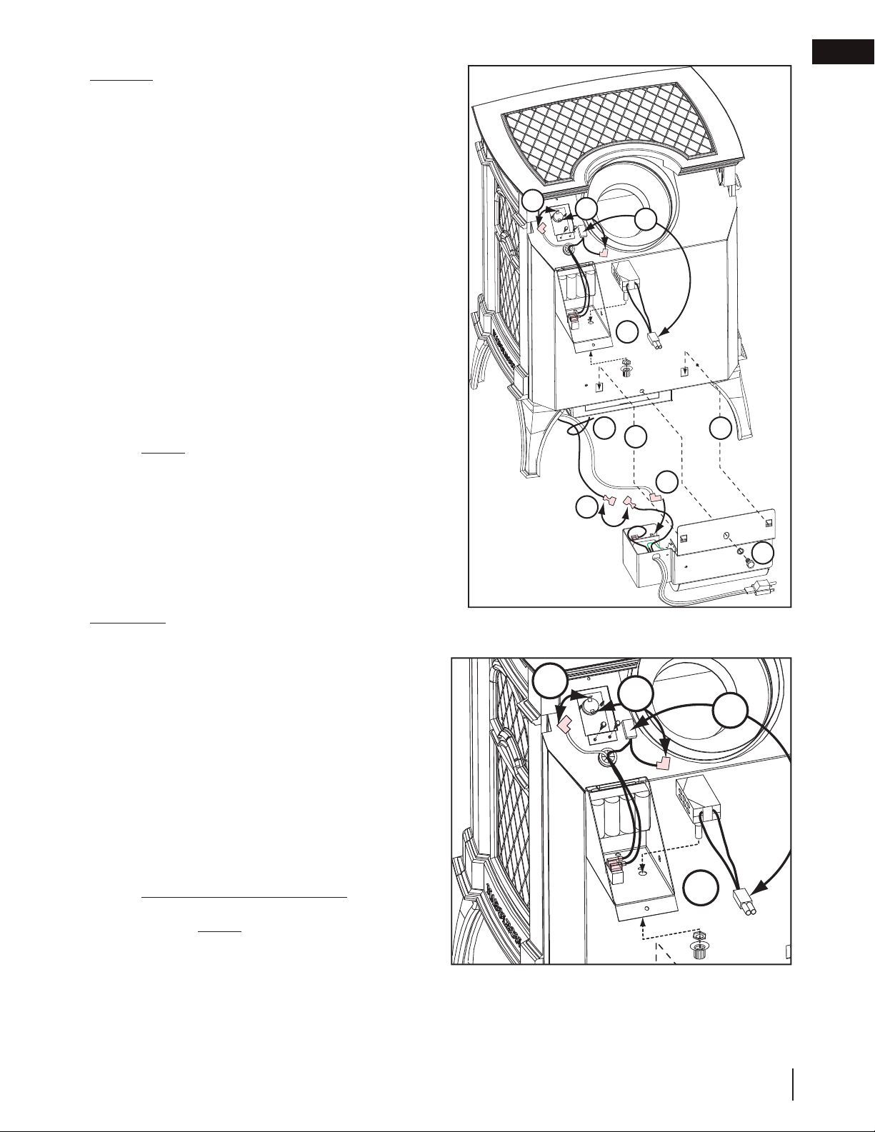
5.0 optional blower installation
A
B
C
D
D
E
G
G
H
I
BLOWER
A. Cut and remove the tie securing the blower
switch wires to the heat shield.
B. Connect the white wire coming from below the
appliance to the terminal on the blower.
C. Connect the black blower wire to the black
wire coming from below the appliance.
D. Insert the clips on the blower housing into the
cutouts in the rear shield. Push down to lock
the clips into position.
E. Secure the blower using the screw and lock
washer supplied.
NOTE: Ensure that all the wires are
tucked into the blower switch housing.
SWITCHES
F. Open the switch housing by removing the top screw.
G. Install the thermal switch bracket as illustrated, using 2
of the screws supplied. Connect the fl agged leads to
the terminals of the thermal switch.
H. Install the variable speed switch (rheostat) into
the housing with the wires facing up. Secure the
switch to the housing using the pal nut and the
knob supplied.
I. Connect the male connector on the switch to the
female connector coming from the appliance.
J. Pilot Indicator Light (millivolt only): Install the
batteries as illustrated. Replace the batteries
annually. NOTE: If replacing the Pilot Indicator
Light, ensure that the red wire lead connects
to the red lead of the thermopile and black to
white.
K. Tuck all of the wires into the housing and close. Secure using the screw removed in Step F.
G
G
H
I
Loading ...
Loading ...
Loading ...