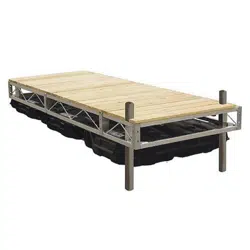
User Manual Guidesman 1764634 Floating Dock
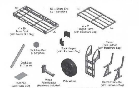
DOOR SECTION AND COMPONENTS
Assembly Instructions:
(Install from shore end out. Allow room for ramp placereyst, ramp will be instaled after dock is securec in place.)
ON LAND
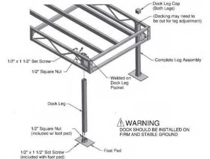
- Insert dock leg into the foot pad and secure with one x1 1/2 set screw and one 1/2" square out as shown
- Insert dock leg into dock leg pocket and secure with two x112 et screw and two 1/2" square nut as shown WHILE STANDING IN THE WATER
- Ajust log he gnt to level dock frame aties installation into water Set the log height so that waves will not hd dock frame
Torque set screws to no more then 15 to 20 tool counds. Do not overighten or leg tube will crush.
DOOR, LEG,WHEEL AXEL ADAPTOR AND POLY WHEEL ASSEMBLY
Assembly Instructions:
ON LAND
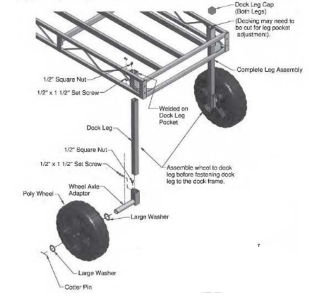
- Insert dock leg into the wheel axie adaptor and secure with one 1/2" x 1 1/2" set screw and one 1/2" square nut as shown.
- Slide one large washer onto the axie shaft, then the poly wheel followed by one large washer Secure with one 1/4" x 2 1/2" cottler pir and bend ends back over axle, top and bottom,
- Insert dock leg into dock leg pocket and secure with two 1/2" x 1 1/2" set screw and two 1/2" square nut as shown WHILE STANDING IN THE WATER
- Adjustment may be needed after dock is rolled into position. Set the leg height so that waves do not hit the dock frame.
Torque set screws to no more then 15 to 20 foot-pounds Do not overtighten or log tube will crush.
STANDING DOCK FRAME CONNECTION

Assembly Instructions:
WHILE STANDING IN THE WATER
- Align dock ends and connect with 1/2" x 1 1/2" hex bolls hand tight (in four locations).
- Fully tighten boits with wrenches after all bolts are installed until lock washers are flat
FLOATING DOCK HINGE CONNECTION
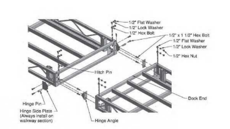
Hinge Assembly Instructions:
ON LAND
- Attach hinge side plates with two 1/2" x 1 1/2" hex bolts, washer, lock washer and nut to one dock section as shown .Tighten until the lock washers are flat.
- Attach hinge angles with two 1/2" x 1 1/2" hex bolts, washer lockwashers and nuts to the other dock section as shown. Tighten with wrenches until the lock washers are flat. WHILE STANDING IN THE WATER
- When docks are floating on calm water, insert one ninge pin and one hitch pin on each side.
FLOAT CONNECTION
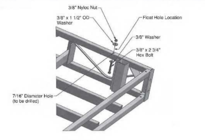
Float connection Instructions:
ON LAND
- Fip dock upside down
- Use final to incate holes and mark on the center of dock frame Position ficat so bolts are easily installable. Use approved Manaros float or ecual
- Drill kur 7/16" holes trough dock frame using boat holes as a template. Wear Safety Glasses
- Drill boult through 3/8" washer, put through frame, float 1 1/2" CD washer and 3.8" nyloc nut hand tight.
- When all four bolts are in place sighten al nuts so lost is secure to dock frame. Do not overtighten Oventightening will damage toat.
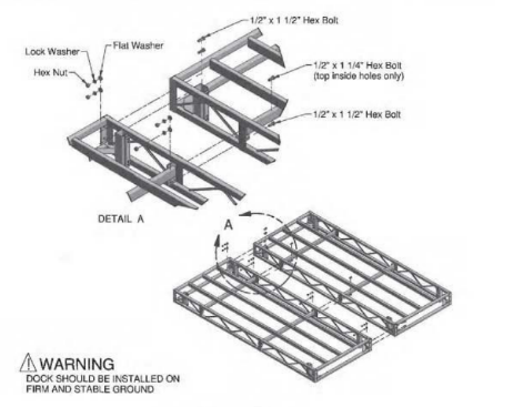
Assembly Instructions:
WHILE STANDING IN THE WATER
- Align dock sides and connect with six 1/2" x 1 1/2" hex bolts and two 1/2" x 1 1/4" hex bolts. Hand Sighten in eight locations.
- Finish tightening bolts with wrenches after all bolts are installed un lock washers are flat
NOTE:
When connecting a standing dock platform, each person should have a boll and nut to place in the corner holes to hold up the side of the dock while the remaining bolts, washers and nuts are inserted
RAMP CONNECTION
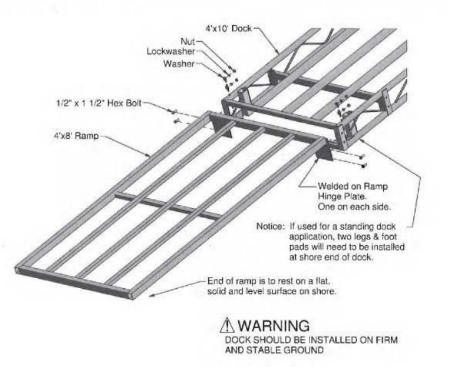
Assembly Instructions:
- Align hinge end of ramp to end of dock.
- Insert 1/2" x 1 1/2' hex bolt through ramp hinge plate and dock corner angles, install washer, lock washer and nut. Hand tighten in four locations.
- After all hardware is installed, tighten with wrench until lock washers are flat.
Ramp is typically installed after dock section(s) are secured in the water.
THREE STEP LADDER ASSEMBLY AND INSTALLTION
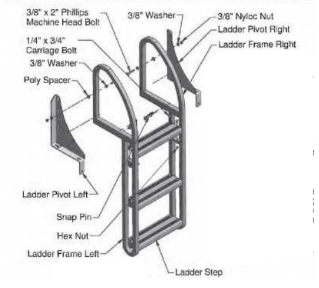
Assembly Instructions:
- Attach each ladder step to the ladder frame left and the ladoer frame right. Secure steps to ladder frame with two 1/4" x 3/4 carriage bolts and two 1/4" nuts.
- Attach the ladder frame right and ladder frame left each to one ladder pivot. Secure with one 3/8" x 2" phillips head machine boll, two poly spacers two 3/8" fiat washers and one 3/8" nut myloc- as shown.
While the ladder is in use secure it down with two snap pins (as shown).
NOTICE: It the ladder is to be pivoted to a vertical position, the 3/8" bolts should go through the middle hole on the ladder pivot bracket and the lower hole on the ladder assembly as shown). # the ladder is to be pivoted to a horizontal position across the dock, the 3/8" x 2" bolt should go through the upper hole on both the ladder pivots and the ladder assembly. To pivo lader, snap pins need to be removed
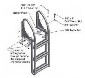
Installation Instructions:
Drilling Required
- Locate ladder where hole locations will not interfere with dock frame.
- Mark locations using ladder as template.
- Drill 7/16 holes where marked.
- Boll ladder to dock with two 3/8″ x 3 1/2″ bolts and two 3/8" x 4" full thread bolts as shown. Backer plates should be installed below deck.
Decking must be secured to the dock frame. See your prefered decking assembly instructions for further detail.
ON DECK BENCH ASSEMBLY AND INSTALLATION
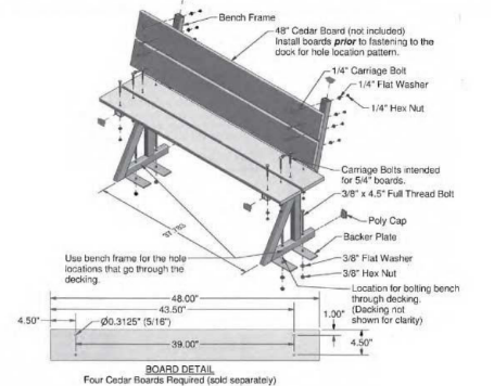
Assembly Instructions:
- Cut and drill four boards per the BOARD DETAIL drawing above.
- Attach boards to bench frame using four 1/4" x 2 1/2" carriage bolts. washers and nuts per board as shown. (4 boards complete bench)
- Locate bench in desired location on dock and confirm that mounting holes do not interfere with dock framą.
- Mark mounting hole locations and drill 7/16" holes through docking
- Mount bench to dock using four 3/8" x 4 1/2" full thread bolts. washers, backer plates and nuts. Put all bolts in before tightening. Backer plates go below the decking.
- Insert poly caps into end of tubes
Notice
Decking must be secured to the dock frame. See your prefered decking assembly instructions for further details
WOOD TOP DECKING ASSEMBLY INSTALLTION
Assembly Instructions:
1. Cut boards at 47 3/4" so ends of boards will be flush to side rails.
2. Position one board flush with each end rail tube and one exactly in the middle. (see diagram)
3. Clamp each end of board before drilling (use a scrap piece of board, if needed, to protect the surface of the deck board), then drill the six screw positions with the 9/64 bit. Fasten each board with six #10 x 1 1/2" sheet metal screws. Do not overtighten. Overtightening will crack the deck board.
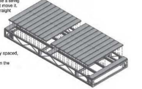
Notice: After each end board is fastened, the very end screws can be backed out enough to be a string line on. Tie string tight so wind doesn't move it. This will help keep your screws in a straight line during the placement of the remaining boards.
4. Position remainder boards, equally spaced, between the existing boards.
5. Use method from Step #3 to fasten the remaining boards.
WOOD TOP PANEL ASSEMBLY INSTRUCTION
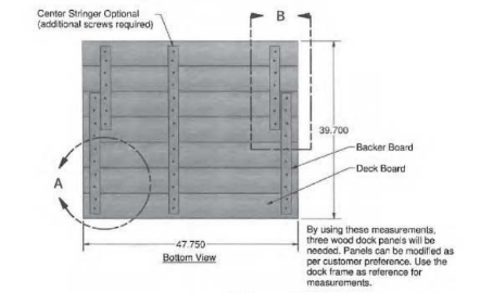
Assembly Instructions:
1. Measurements shown will make three panels for coverage of x 10 dock frame. Any size panels can be made.
Notice:
Use dock frame for the layout pattern & measurements.
Assembler may want to make a flat square frame (g) to help position the deck boards until they are fastened together.
2. Refer to pg. 17 for further details before continuing
3. Equally space out boards and measure placement of backer boards (deck boards ripped in half) that will fit snug on the inside of the aluminum tubes.
4. Glue the back of the deck boards where the placement of the backer boards will be. Use caution when applying the glue so that when the backer board is tightened the glue doesn't squeeze out and damage the top of the deck boards.
5. Screw backer board to deck boards with the #8 x 1 1/2" screws as shown. Use caution as not to overtighten. Overtightening the backer boards may cause the screws to poke through the top of the deck boards or crack the backer boards
WOOD TOP PANEL DETAIL DRAWINGS
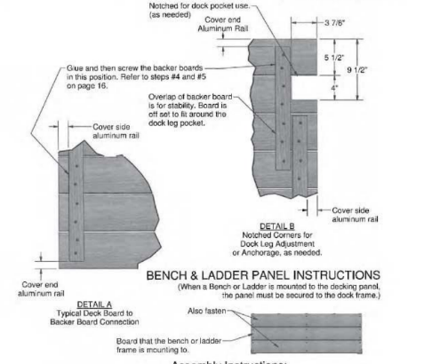
Assembly Instructions:
- Faston the panel's board that the frame is directly mounted on and the boards on each side, as shown. Fasten the ends and middle of the boards of the panel to the aluminum frame. Do this also for the other frame where it's needed.
- Drill and screw deck boards to the aluminuc rail. similar to Step #3 on pg. 15) minute
- Then follow the steps to install the Bench or Ladder as instructed on paans 13 and 14.
PS 1320 RESIN DOCK TOP ASSEMBLY INSTRUCTIONS
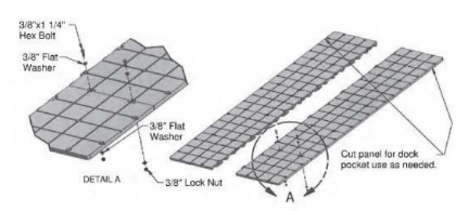
Assembly Instructions:
- Boll together two halves as shown. Tighten finger tight (16 connections)
- Connect two halves together and position centered on dock frame. Use x 1 1/2" sell-drilling hex screws and 1/4" fender washers to fasten decking to the dock frame. Start down the center then finish around the perimeter
- Finish fightening the nut and belt connections Do not overtighten. Overtightening will damage the panels.