Loading ...
Loading ...
Loading ...
19
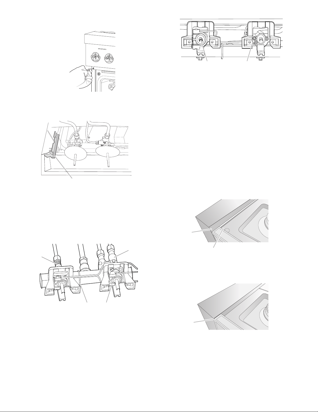
3. Open the oven door and remove the two screws on each
side of the range that hold the control console in place.
NOTE: Make sure to leave the door open or the control
console will not rest in the side brackets properly once it is
attached.
4. Pull up on the control console and let it drop forward into the
notched console brackets on each side.
5. Locate the appropriate low-turndown screw for the
appropriate burner on the given valve. The low-turndown
screw for the left rear, right rear, center rear, and center front
burner valves (aluminum) is located through the center of
the valve stem. The low-turndown screw for the left front
and right front burner valves (brass) is located behind the
ignition switch on the valve body, left of the stem. To remove
the ignition switch cut the wire tie and pull the switch off the
valve stem.
6. With the burner ON (the burner will have to be lit manually
with a lighter), and set to simmer LOW, adjust the simmer
ame down to the proper BTU level. Using a 1/8" x 4¼"
(3.2mm x 108 mm) at blade screwdriver, turn the simmer
low-turndown adjustment screw clockwise until the ame
height is at, or below, the bottom of the cap. If the ame
becomes unstable and ickers or appears to race around the
burner, the adjustment is too low and the screw should be
adjusted counterclockwise until the ame is stable. Repeat
this step for all surface burners.
NOTE: Use a knob to adjust the burner valve.
NOTE: Adjust each burner individually.
7. After adjustments are completed, replace the ignition
switches onto the valves.
8. Lift up on the control console and set it back into place. For
a proper t, the ange of the control console must hook over
the lip on the front of the range cooktop.
NOTE: It may be necessary to lift valve stems to align with
console holes.
9. Check that the control console is ush with the top edge of
the range.
10. Replace the screws on each side of the control console.
11. Replace the bezels using the 2 screws which attach to the
valve brackets, making note that there are front and rear
bezels and will only attach properly in the correct location on
the console.
12. Push the Surface Knobs onto the valve stems.
13. Replace the burner grates.
A
A. Control console bracket
A. Control console flange
B. Front lip of range cooktop
A
B
A. Flush with range top
A
A. Aluminum Valve for Left Rear, Right Rear,
Center Rear, and Center Front burners
B. Brass Valve for Left Front and Right Front
Dual burners
C. Wire Tie
D. Ignition switch
DC
B
A
BA
A. Low-turndown adjustment screw for
Aluminum Valve through center of stem
B. Low-turndown adjustment screw for Brass
Valve
Loading ...
Loading ...
Loading ...