
Loading ...
Loading ...
Loading ...
5. HEALTH AND SAFETY INFORMATION
- 6 -
- 11 -
GENERAL SAFETY INSTRUCTIONS
Warning: Please read all safety warnings and all details carefully. Failure to follow the warnings
may result in serious injury or major component damage.
Important: Draper Tools recommends that this product should not be modified or used for any
application other than that for which it was designed.
Save all warnings and instructions for future reference.
1) Personal safety
a) Stay alert, watch what you are doing and use common sense when using this product.
Do not use this product while you are tired or under the influence of drugs, alcohol or any
medication. A moment of inattention while using this product may result in serious personal
injury.
b) Use personal protective equipment as necessary.
c) Check and remove any part of the product before turning/testing the engine. A part left
attached to a rotating part of the engine may result in personal injury or major component
damage.
d) Carefully clean the tool components after every use.
f) Keep the tool components safe and tidy.
g) Do not use this product for any purpose other than for which it is designed.
Warning! Some of the packaging materials used may be harmful to children. Do not leave any of
these materials in the reach of children.
If any of the packaging is to be thrown away, make sure it is disposed of correctly; according to
local regulations.
9. PROCEDURE AND APPLICATION GUIDE
Basic component use.
• Lock the Engine with all pistons at equal heights, use a suitable rod or measurement tool to
ensure piston 3 and 4 are level. Insert the flywheel timing pin (E).
• Ensure the camshafts are correctly aligned with their alignment flats positioned as shown.
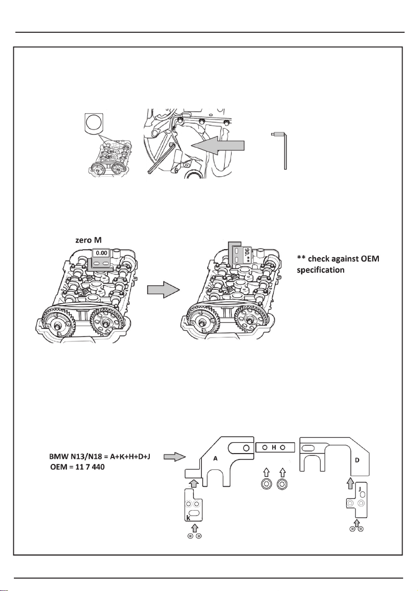
• Use components (M) digital inclinometer and (O) to check the chain stretch in accordance
with OEM specification (PSA). Place (M) and (O) on the cylinder head as shown and zero
M. move components (M) and (O) so that the angle of the side flat of the camshaft is
displayed on (M) as shown. Compare to OEM specification.
• Lock both camshafts with component A + B or A + D with appropriate alignment adaptors as
dictated by the OEM part numbers required.
• NB: Mount the camshaft locking components with the link bar (H) facing the Gear box end
of the engine.
For BMW N13 and N18 Engines assemble the camshaft locking components as shown.
Loading ...
Loading ...
Loading ...