DUCTED CONCEALED (CEILING RECESSED) MINI SPLIT SYSTEM
AIR CONDITIONER/HEAT PUMP
MEDIUM EXTERNAL STATIC PRESSURE TYPE
IMPORTANT NOTICE:
Please read this manual carefully before installing
or operating your new air conditioning system.
Be sure to save this manual for future reference.
Installation
Manual
RAB/RYB Series
RAB: Cooling Only Version
RYB Cooling and Heating Version
Inverter+ and Inverter++ Models
9,000-48,000 BTU/hr

If your indoor unit is a part of a MULTI-SPLIT system set, refer to the installation manual
that is packed with your outdoor unit as well.
Accessories.......................................................................05
a. Indoor Unit Parts.........................................................08
b. Indoor Unit Installation Instructions............09
Safety Precautions....................................................06
Outdoor Unit Installation ....................................13
a. Outdoor Unit Installation Instructions
..........
13
b. Outdoor Unit Types and Specifications
........14
c. Notes on Drilling Wall Hole
....................................
15
Drainpipe Installation ...........................................16
Table of Contents
Installation Manual
Indoor Unit Installation
.......................................08
Installation Overview............................................07
1
2
5
3
4
6
Page 3
Refrigerant Piping Connection ...............................18
A. Notes on Pipe Length and Elevation......................18
B. Refrigerant Piping Connection Instructions.....20
Wiring ...................................................................23
a. Outdoor Unit Wiring .............................23
b. Indoor Unit Wiring.................................24
c. Power Specifications.............................26
Air Evacuation ....................................................................28
a. Evacuation Instructions..............................................28
b. Note on Adding Refrigerant
...................................29
Test Run .............................................................30
MC MC
7
8
9
10
L1 L2
Impedance Information 31
11
..................
Page 5
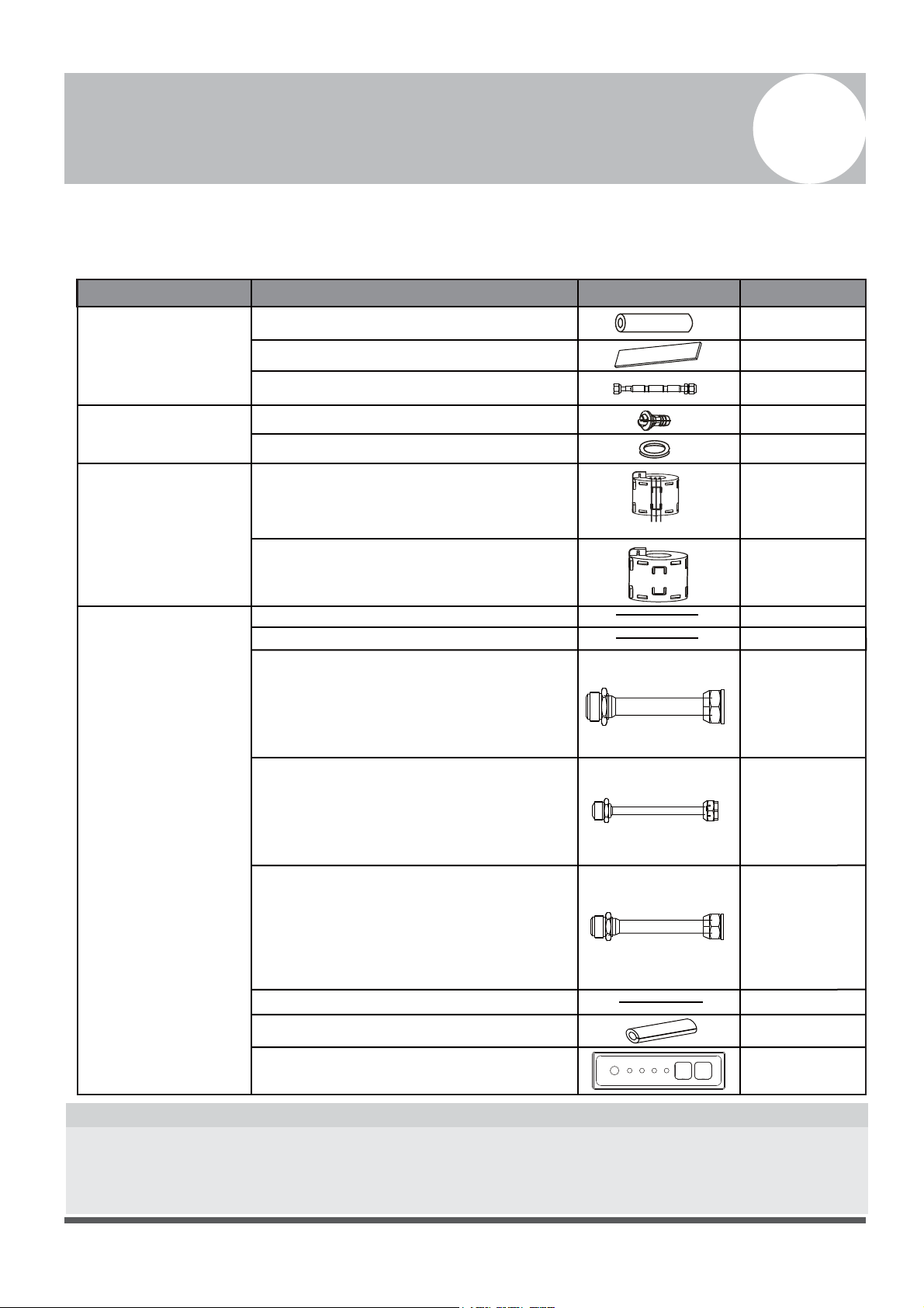
Accessories
1
The air conditioning system comes with the following accessories. Use all of the installation parts
and accessories to install the air conditioner. Improper installation may result in water leakage,
electrical shock and re, or equipment failure.
Connecting Wire for Display (2m)
Cord Protection Rubber Ring
QUANTITY
SHAPE
NAME
Soundproof/Insulation Sheath
2
1
1
1
Tubing & Fittings
Others
Installation Manual
Transfer Connector (Φ12.7-Φ15.9)/
( )(Packed with the indoor unit )
NOTE: Pipe size may dier from appliance to
appliance. To meet dierent pipe size requirements,
sometimes the pipe connections need a transfer
connector installed on the outdoor unit .
Transfer Connector (Φ6.35-Φ9.52)/
( )(Packed with the indoor unit)
NOTE: Pipe size may dier from appliance to
appliance. To meet dierent pipe size requirements,
sometimes the pipe connections need a transfer
connector installed on the outdoor unit .
Transfer Connector (Φ9.52-Φ12.7)/
( ) (Packed with the indoor unit,
used for multi-type models only )
NOTE: Pipe size may dier from appliance to
appliance. To meet dierent pipe size requirements,
sometimes the pipe connections need a transfer
connector installed on the outdoor unit .
1
Owner‘s Manual
Drain Joint (some models)
Seal Ring (some models)
Drainpipe Fittings
(for cooling & heating)
Seal Sponge (some models)
EMC Magnetic Ring
(some models)
Magnetic Ring
(wrap the electric wires S1 & S2 ( P & Q & E )
around the magnetic ring twice)
Magnetic Ring
(Hitch on the connective cable between the indoor
unit and outdoor unit after installation.)
1
1
Orice (some models)
1
Φ0.5in-Φ0.63in
Φ0.25in-Φ0.375in
Φ0.375in-Φ0.5in
1
(on some models)
1
(on some models)
1
(on some models)
1(on some models)
1(on some models)
1
Optional accessories
There are two types of remote controls: wired and wireless.
Select a remote controller based on customer preferences and requirements, and install in an
appropriate place.
Refer to catalogues and technical literature for guidance on selecting a suitable remote controller.
•
S1&S2(P&Q&E)
Display Panel
*For testing purposes only
1(on some models-
KJR-120G,KJR-120H)
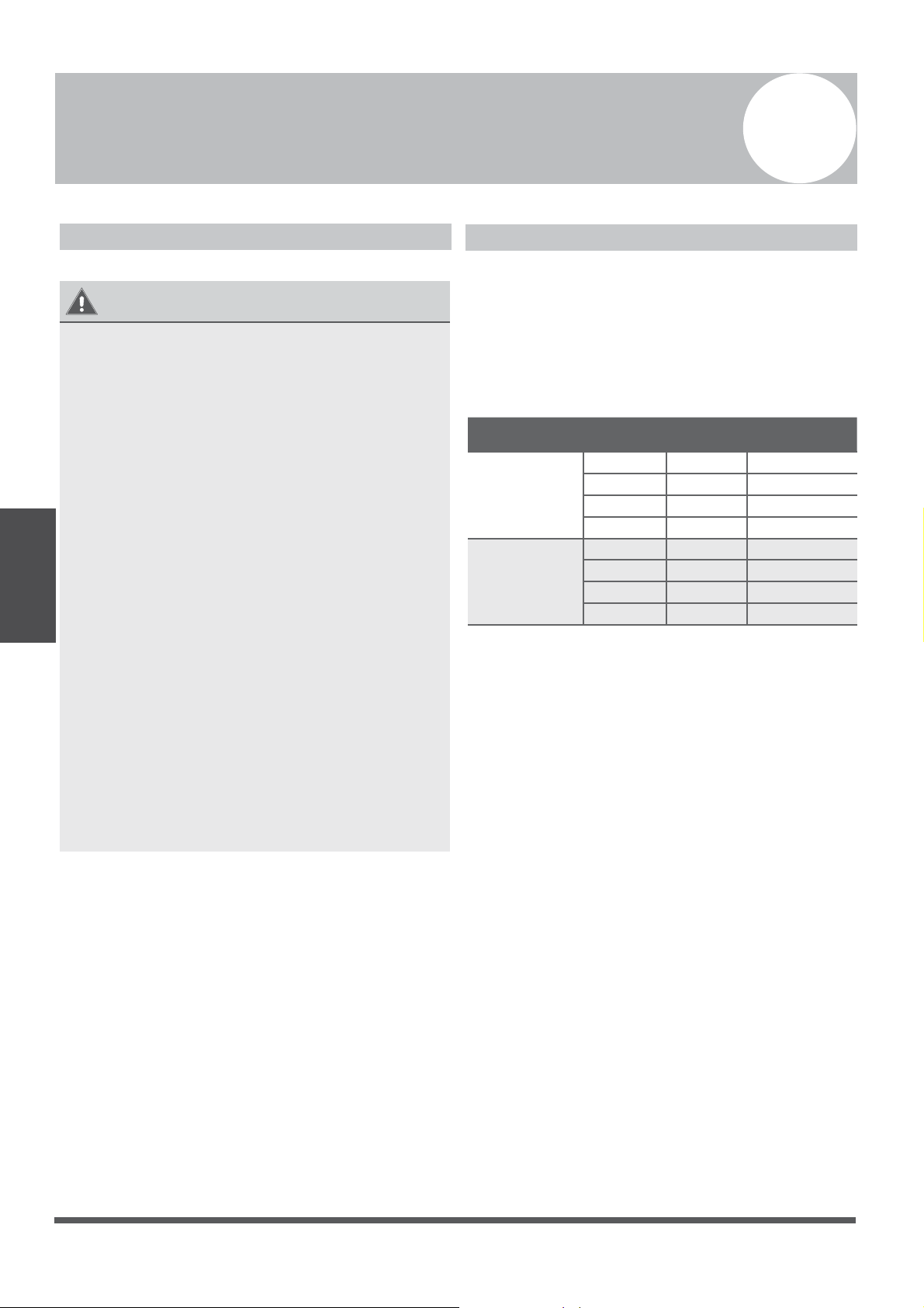
Safety Precautions
2
Read and Understand Safety Precautions Prior to Installation
Improper installation due to negligence of instructions may result in serious damage or injury.
The magnitude of potential damages or injuries is classified as either a WARNING or a CAUTION.
WARNING
• Read the Safety Precautions carefully before installation.
• In certain functional environments, such as kitchens, server rooms, etc., the use of specially
designed air-conditioning units is highly recommended.
• Only trained and certied technicians should install, repair, and service this air
conditioning unit.
• Attempts to self-install can lead to inecient performance, and risk of equipment damage over
time.
• Strictly follow the installation instructions set forth in this manual.
• Improper installation may result in electrical shock, short circuit, leaks, fire or other damage to
the equipment.
• Before you install the unit, consider strong winds, typhoons, and earthquakes that might aect
your unit, and locate it accordingly. Failure to do so could cause the equipment to fail.
• After installation, ensure there are no refrigerant leaks and that the unit is operating properly.
Refrigerant is both toxic and flammable, and poses a serious health and safety risk.
Note about Fluorinated Gases
1.
This air-conditioning unit contains fluorinated gases. For specific information on the type of gas
and the amount, please refer to the relevant label on the unit itself.
2.
Installation, service, maintenance, and repair of this unit must be performed by a certified
technician.
3.
Product uninstallation and recycling must be performed by a certified technician.
4.
If the system has a leak-detection system installed, it must be checked for leaks at least every 12
months.
5.
When the unit is checked for leaks, proper record-keeping of all checks is strongly recommended.
Failure to observe a warning may result in death. The product must be installed by
installers or contractors who are licensed HVAC professionals and in compliance with
all local, state, and provincial laws.
Failure to observe a caution may result in injury or equipment damage.
WARNING
CAUTION
Page 6
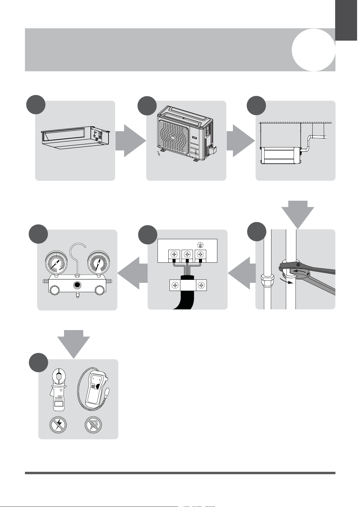
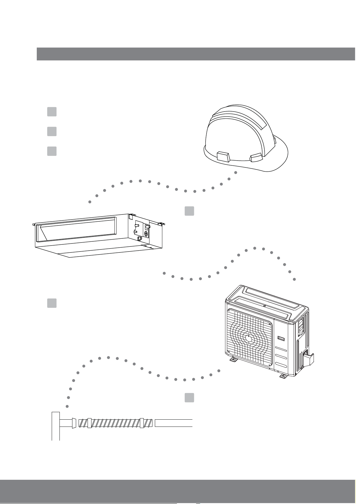
Installation Overview
3
Unit Installation
Overview
L1 L2
1
2
3
4
5
MC MC
6
7
Install the Indoor Unit
(Page 8)
INSTALLATION ORDER
Install the Outdoor Unit
(Page 13)
Install the Drainpipe
(Page 15)
Evacuate the Refrigeration System
(Page 26)
Connect the Wires
(Page 23)
Connect the Refrigerant Pipes
(Page 18)
Perform a Test Run
(Page 28)
Page 7
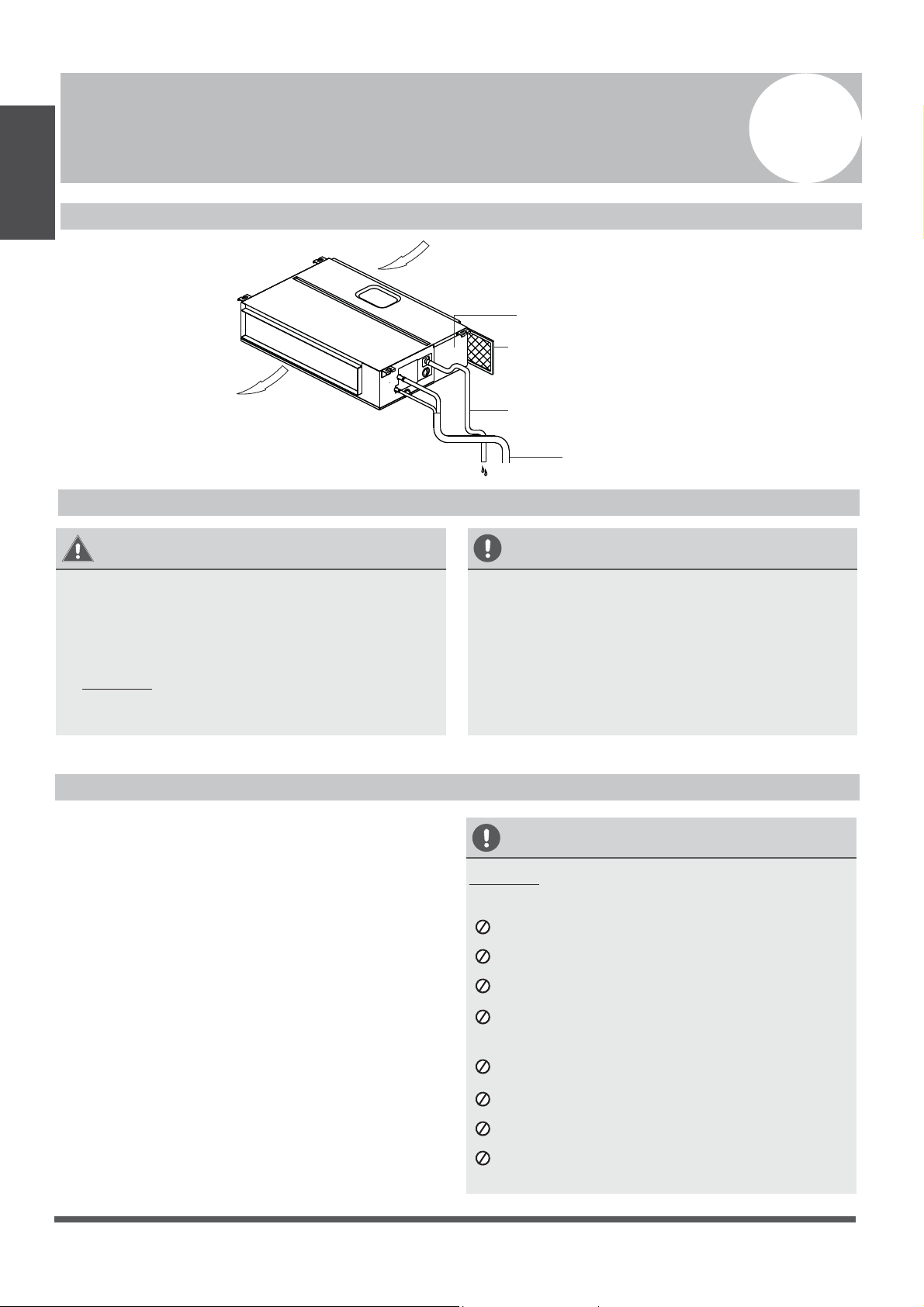
Indoor Unit Installation
4
Indoor Unit
Installation
Indoor Unit Parts
Fig. 4.1
WARNING
• Securely install the indoor unit on a structure
that can sustain its weight. If the structure is
too weak, the unit may fall, causing personal
injury, unit and property damage, or even
death.
• DO NOT install the indoor unit in a bathroom
or laundry room, as excessive moisture can
short the unit and corrode the wiring.
CAUTION
• Install the indoor and outdoor units, cables,
and wires at least 1m (3.2’) from televisions
or radios, to prevent static or image
distortion. Depending on the appliances, a
1m (3.2’) distance may not be sufficient.
• If the indoor unit is installed on a metal
part of the building, it must be grounded.
Indoor Unit Installation Instructions
Step 1: Select installation location
The indoor unit should be installed in a location
that meets the following requirements:
Enough room for installation and maintenance.
Enough room for the connecting pipe and
drainpipe.
The ceiling is horizontal, and its structure can
sustain the weight of the indoor unit.
The air inlet and outlet are not impeded.
The airflow can fill the entire room.
There is no direct radiation from heaters.
CAUTION
DO NOT install the unit in the following
locations:
Where oil drilling or fracking is taking place.
Coastal areas with high salt content in the air
Near geothermal activity and corrosive gas
Buildings that may experience power
uctuations
Enclosed spaces
Areas with strong electromagnetic waves
Areas that store ammable materials or gas
Rooms with high humidity, such as
bathrooms or laundry rooms
Air Outlet
Air Inlet
Air filter(on selected models)
Drain hose
Electric control cabinet
Refrigerant connecting pipe
√
√
√
√
√
√
Safety Precautions
Page 8
It is an embeded installation.
√
Models with a cooling capacity of 9000 BTU to
18000 BTU are only applicable to one room.
√
Indoor Unit
Installation
Air Outlet
Air Inlet
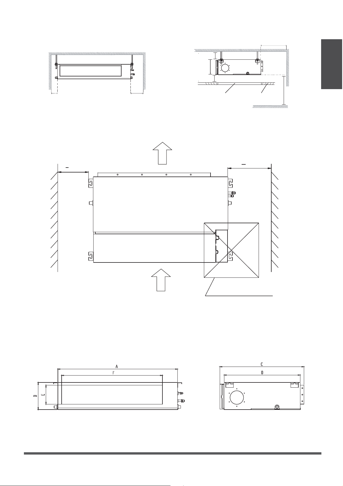
Step 2: Hang the Indoor Unit.
1. Please refer to the following diagrams to locate the four positioning screw bolt holes on the
ceiling. Be sure to mark the places where you will drill ceiling hook holes.
Maintenance Space
Installation Location
Left
Side
Right
Side
Strong, durable ceiling
Indoor Unit
>4in (10cm) >12in (30cm)
>0.8in (2cm)
>3/4 in(2cm)
>11.8in (30cm)
> 8’ (250cm)
Floor
Service Access Ceiling
(When no ceiling)
B
Fig. 4.2
Air Outlet dimensions
Page 9
> (20cm)
8
in
12in
24inx24in (60cmx60cm)
inspection opening
> (30cm)
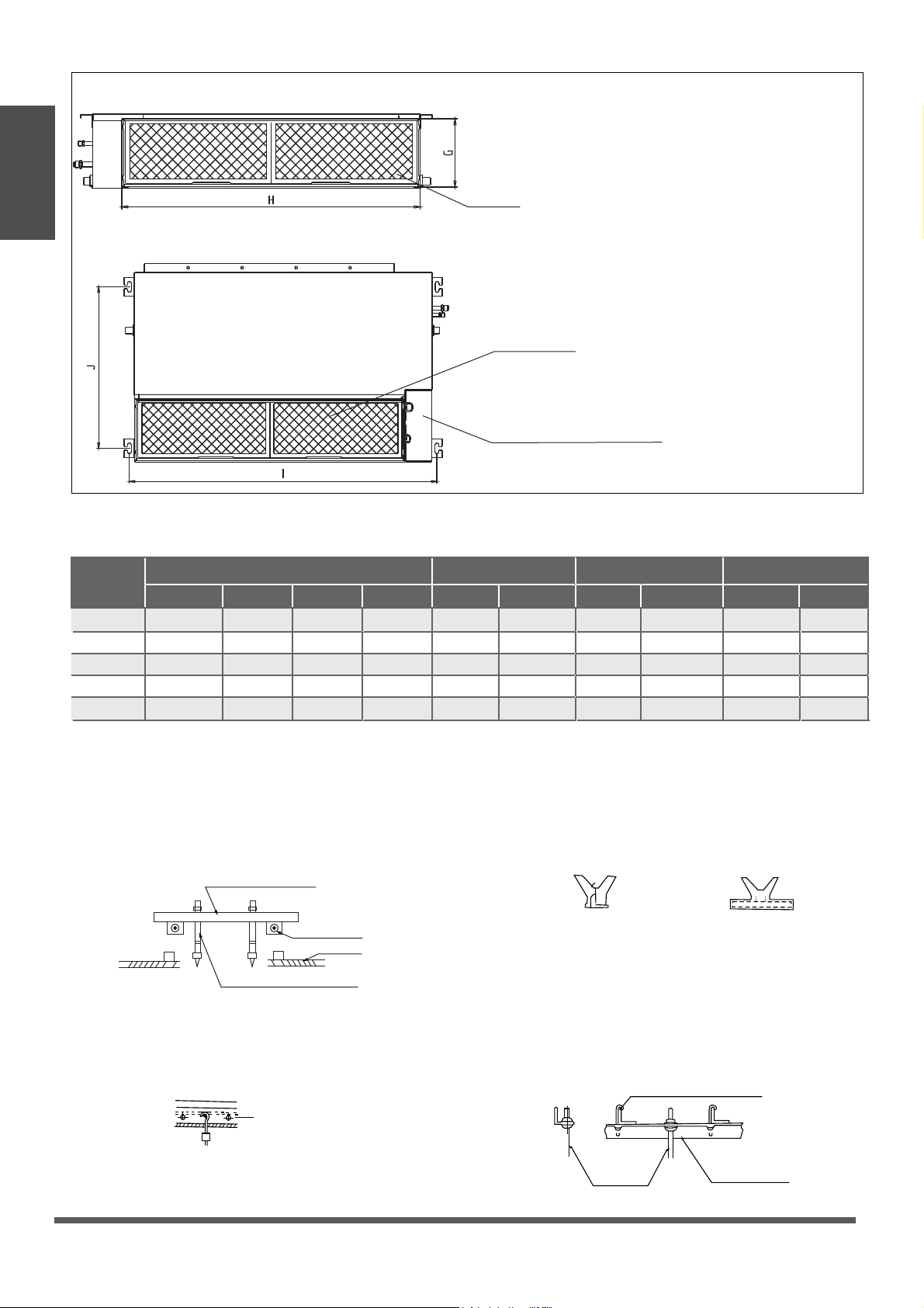
Fig. 4.3
Air Filter
Descending Ventilation Opening and Mounted Hook
Air Filter
Electric Control Box
Table.4-1 (unit: mm/inch)
MODEL
(Btu/h)
Outline dimension
ABC
Air Outlet Opening size
DEF
Air Return Opening size
Size of Mounted Lug
I
J
G
H
18K 210/8.3 674/26.5880/34.6
24K 249/9.8 774/30.51100/43.3
30K~36K 249/9.8 774/30.51360/53.5
36K~60K 300/11.8 874/34.41200/47.2
136/5.4 706/27.8600/23.6
175/6.9 926/36.5700/27.6
175/6.9 1186/46.7700/27.6
227/8.9 1044/41.1800/31.5
190/7.5
228/8.9
228/8.9
280/11
920/36.2782/30.8
1140/44.91001/39.4
1400/55.11261/49.6
1240/48.81101/43.3
508/20
598/23.5
598/23.5
697/27.4
9K/12K
200/7.9 506/19.9700/27.6
152/6 537/21.1450/17.7 186/7.3 741/29.2599/23.6
360/14.2
Indoor Unit
Installation
Fig. 4.6
Fig. 4.7
Original Concrete Bricks
Use an embedding screw bolt, crock, and stick
harness. (See Fig. 4.6)
Steel Roof Beam Structure
Install and use the steel supporting angle.
(See Fig. 4.7)
Fig. 4.4
Wood
Place the wood mounting across the roof beam,
then install the hanging screw bolts. (See Fig. 4.4)
Wood Mounting
Roof Beam
Hanging Screw Bolts
Ceiling
Fig. 4.5
New Concrete Bricks
Inlay or embed the screw bolts. (See Fig. 4.5)
(Blade shape insertion)
(Slide insertion)
Steel Bar
Embedding Screw Bolt
(Pipe Hanging and Embedding Screw Bolt)
Hanging Screw bolt
Hanging
Bolts
Steel
Supporting Angle
Page 10
Air Inlet dimensions
Indoor Unit
Installation
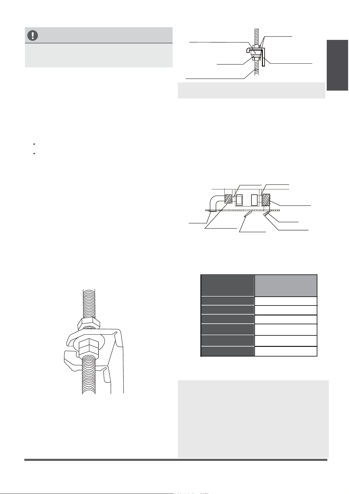
Fig. 4.10
Step 3: Duct and Accessories Installation
NOTE: 1. Do not place the connecting duct
weight onto the indoor unit.
2. When connecting the duct, use a
nonammable canvas tie-in, to prevent
vibrating.
3. Insulation foam must be wrapped outside the
duct to avoid condensate. An internal duct
underlayer can be added to reduce noise,
if the end-user requires.
1. Install the lter (optional), according to the size
of the air inlet.
5. Refer to the following static pressure guidelines
when installing the indoor unit.
Change the fan motor static pressure
according to external duct static pressure.
2. Install the canvas tie-in between the body and
the duct.
3. The air inlet and air outlet duct should be far
enough apart to a avoid air passage
short-circuiting.
4.
Connect the duct according to the following
diagram:
Canvas Tie-In Canvas Tie-In
Air Outlet
Isolation Booth
Isolation booth
Checking Orice
Air Inlet
Air Dust Filter
Table.4-2
MODEL
(Btu/h)
Static Pressure
(Pa/in.wg)
0~100/0~3/8
18K
0~160/0~5/8
24K
0~160/0~5/8
30K~36K
0~160/0~5/8
42K~60K
0~50/0~1/4
9K
0~50/0~1/4
12K
Cut o the roof beam.
Strengthen the point at which the cut
was made. Consolidate the roof beam.
Fig. 4.9
Screw Nut
Washer
Hanging Screw Bolt
Overhang Part
Shockproof Cushion
NOTE:
Conrm the minimum drain tilt is 1/100
or more.
CAUTION
The unit body must be completely aligned with
the hole. Ensure that the unit and the hole are
the same size before moving on.
2.
Install and t pipes and wires after you have
nished installing the main body.When
choosing where to start, determine the
direction of the pipes to be drawn out.
Especially in cases where there is a ceiling
involved, align the refrigerant pipes, drain
pipes, and indoor and outdoor lines with their
connection points before mounting the unit.
3.
Install hanging screw bolts.
4.
After you select an installation location, align
the refrigerant pipes, drain pipes, as well as
indoor and outdoor wires, with their
connection points, before mounting the unit.
5.
Drill 4 holes 10 cm (4”) deep at the ceiling
hook positions in the internal ceiling. Be sure
to hold the drill at a 90° angle to the ceiling.
6.
Secure the bolt using the washers and nuts
provided.
7.
Install the four suspension bolts.
8.
Mount the indoor unit, with at least two
people to lift and secure it. Insert suspension
bolts into the unit’s hanging holes. Fasten
them using the washers and nuts provided.
(See Fig. 4.8).
9. Mount the indoor unit onto the hanging
screw bolts with a block. Position the
indoor unit atly, using a level indicator to
prevent leaks. (See Fig. 4.9).
Fig. 4.8
Page 11
Indoor Unit
Installation
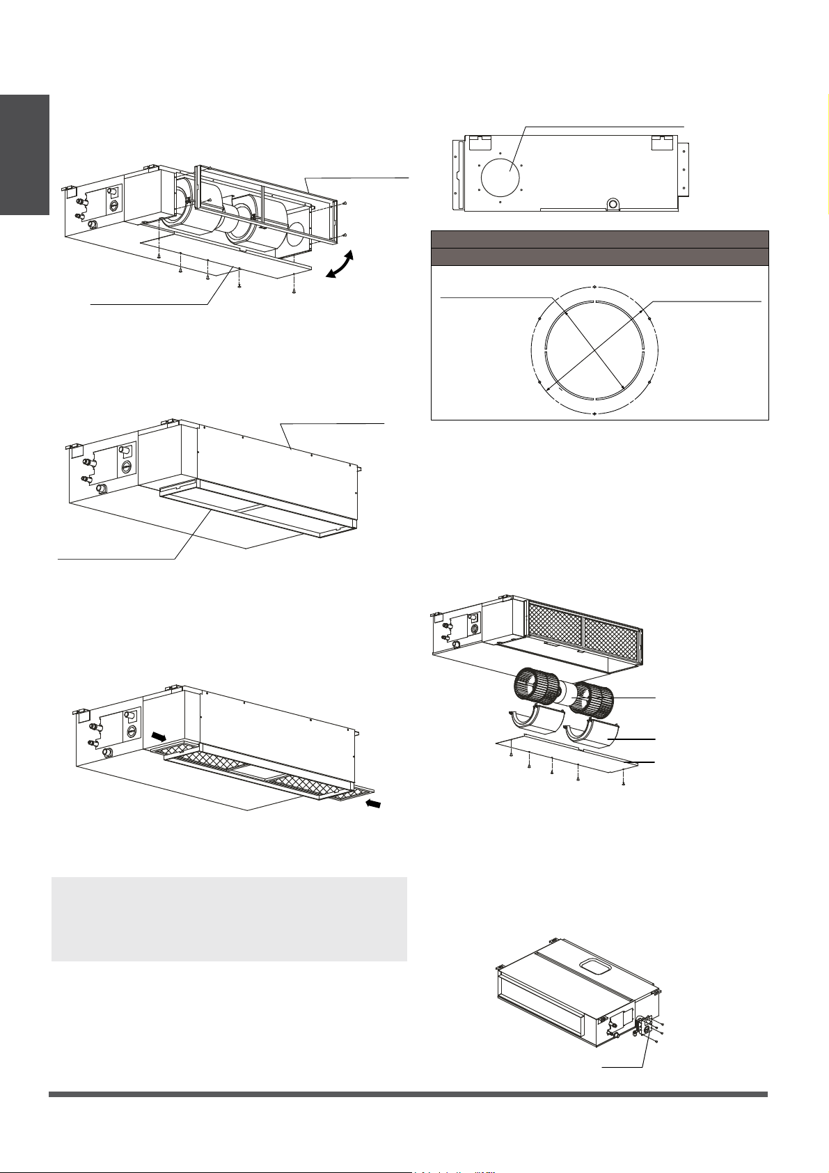
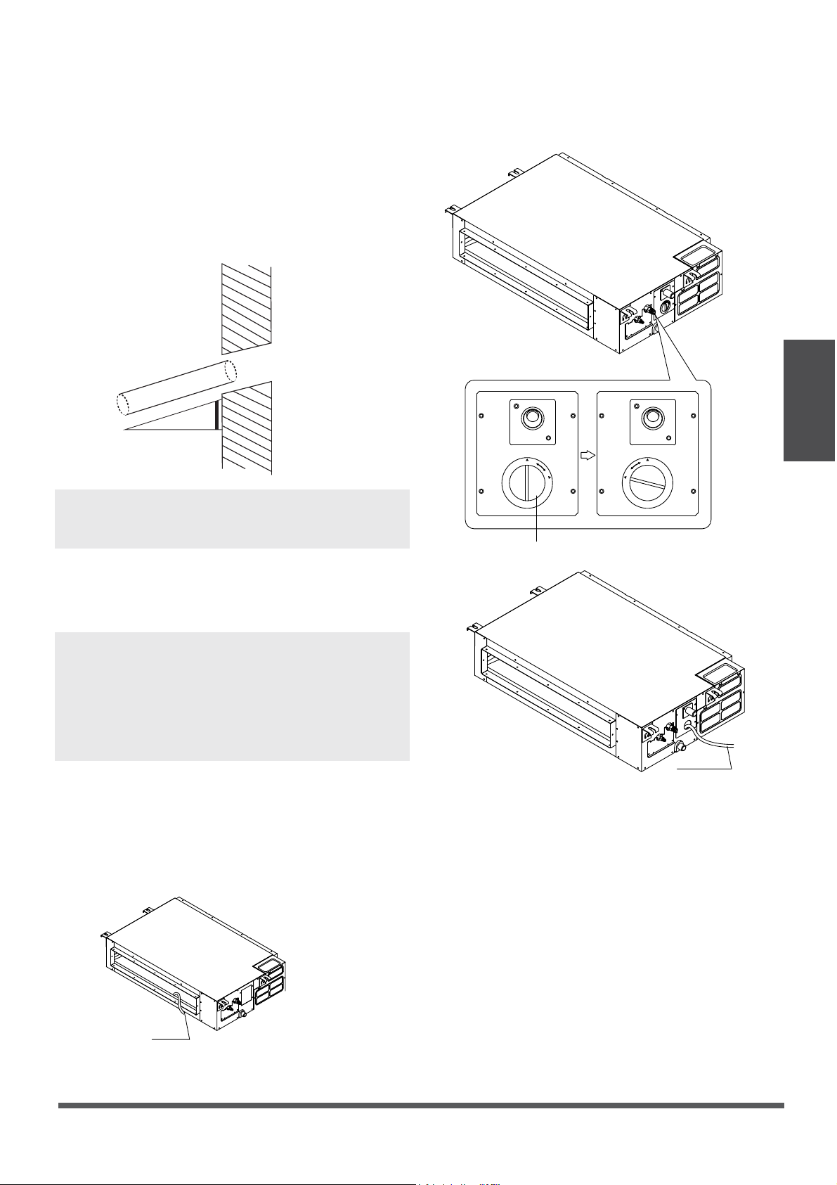
Step 4: Adjust the air inlet direction
(from rear side to under-side).
1. Take o the ventilation panel and ange.
2. Change the mounting positions of the
ventilation panel and air return ange.
Air Return Flange
Ventilation Panel
3. When installing the lter mesh, t it into the
ange, as illustrated in the following gure.
NOTE: All gures in this manual are for
explanatory purposes only. The air conditioner
you have purchased may slightly dier in
design, though it remains similar in shape.
Step 5: Fresh air duct installation
Dimension :
Duct Joint for fresh air
Ø125mm(5”)
Ø160mm (6-1/4”)
MODEL
18-60
Step 6: Motor and drain pump maintenance
Motor Maintenance:
Take o the ventilated panel.
Take o the blower housing.
Take o the motor.
1.
2.
3.
(The rear ventilated panel is used as an example)
Motor
Blower Housing
Ventilated Panel
Pump Maintenance:
Remove four screws from the drain pump.
Unplug the pump power supply and water
level switch cable.
Detach the pump.
1.
2.
3.
Pump
Fig. 4.11
Fig. 4.12
Fig. 4.13
Fig. 4.14
Fig. 4.15
Fig. 4.16
Air Return Flange
Ventilation panel
Page 12
Outdoor Unit Installation
Outdoor Unit Installation Instructions
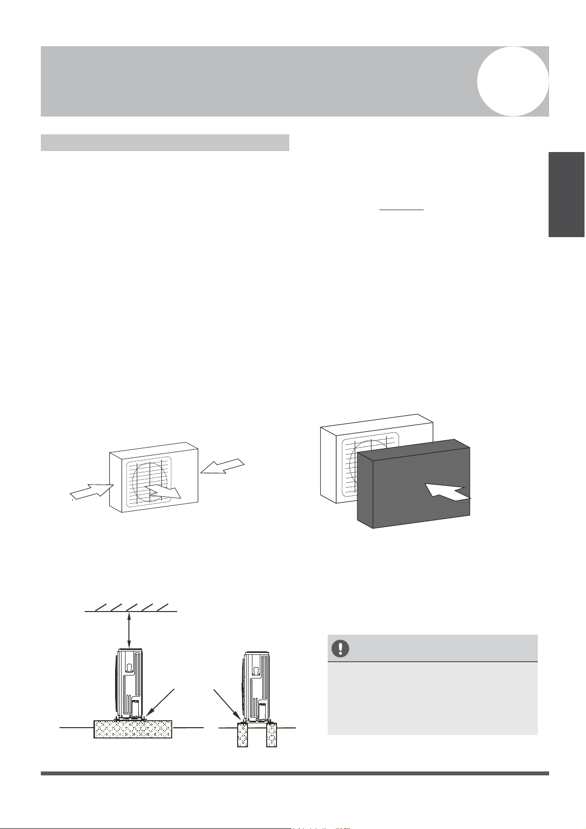
Step 1: Select Installation Location.
The outdoor unit should be installed in a
location that meets the following requirements:
The location is as close to the indoor unit as
possible.
Ensure that there is enough room for
installation and maintenance.
The air inlet and outlet are not
obstructed, or exposed to strong wind.
The location of the unit will not be
subject to snowdrifts, accumulation of leaves,
or other seasonal debris. If possible, provide
an awning for the unit. Ensure the awning
does not obstruct airflow.
The installation area is dry and well
ventilated.
There must be enough room to install the
connecting pipes and cables, and to access
them for maintenance.
The area must be free of combustible gases
and chemicals.
The pipe length between the outdoor and
indoor unit may not exceed the maximum
allowable pipe length.
If possible, DO NOT install the unit where it
will be exposed to direct sunshine.
If possible, make sure the unit is located far
away from the property of neighbors, so that
the unit noise will not cause disturbances.
If the location is exposed to strong winds (for
example: near a seaside), the unit must be
placed against the wall to shelter it from the
wind. If necessary, use an awning.
(See Fig. 5.1 & 5.2)
Install the indoor and outdoor units, cables,
and wires at least 1 meter from televisions or
radios, to prevent static or image distortion.
Depending on the radio waves, a 1 meter
distance may not be enough to eliminate all
interference.
Strong Winds
Strong Winds
Strong wind
Fig. 5.1 Fig. 5.2
Step 2: Install Outdoor Unit.
Fix the outdoor unit with anchor bolts (M10)
>60cm / 23.6”
Fix with Bolts
CAUTION
• Be sure to remove any obstacles that
may block air circulation.
• Refer to Length Specications
to ensure there is enough room
for installation and maintenance.
Fig. 5.3
Outdoor Unit
Installation
5
√
√
√
√
√
√
√
√
√
√
√
√
Page 13
Outdoor Unit
Installation
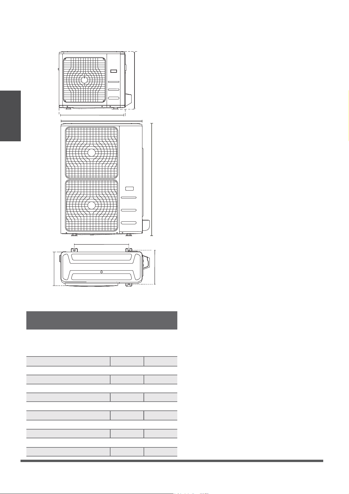
Table 5.1: Length Specications of Split
Type Outdoor Unit (unit: mm/inch)
Split Type Outdoor Unit
(Refer to Fig 5.4, 5.5, 5.6, 5.10 and Table 5.1)
Fig. 5.6
Fig. 5.5
A
B
D
W
H
W
H
Fig. 5.4
Page 14
Outdoor Unit Dimensions
W x H x D
Mounting Dimensions
Distance A Distance B
770x555x300 (30.3x21.9x11.8) 549 (21.6) 325 (12.8)
946 x810x410 (37.24x31.9x16.14) 673 (26.5)
403 (15.87)
952 x1333x415 (37.5x52.5x16.34) 634 (24.96)
404 (15.9)
845x702x363 (33.27x27.6x14.3)
540 (21.26) 350 (13.8)
800x554x333 (31.5x21.8x13.1) 514 (20.24) 340 (13.39)
YN048GMFI17RUD:
YN036GMFI17RUD:
946 x810x410 (37.24x31.9x16.14) 673 (26.5)
403 (15.87)
YN024GMFI22RPD:
YN018GMFI22RPD:
YN012GMFI22RPD:
YN009GMFI22RPD:
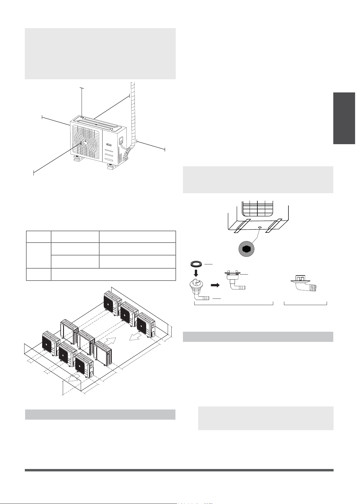
NOTE:
The minimum distance between the
outdoor unit and walls described in the
installation guide does not apply to airtight
rooms. Be sure to keep the unit unobstructed
in at least two of the three dimensions (M, N, P)
(See Fig. 5.10)
M
N
P
30 cm / 12” from back wall
If using brackets, 10cm / 4”
6
0 cm / 24” on right
60 cm / 24” above
30 cm / 12” on left
200 cm / 78” in front
Fig. 5.10
NOTE: Make sure the water drains to a safe
location, where it will not cause water damage
or a slipping hazard.
Seal
Drain Joint
(A) (B)
Base Pan Hole of
Outdoor Unit
Seal
Fig. 5.12
Notes On Drilling Wall Hole
You must drill a hole into the wall for the
refrigerant piping and the signal cable that will
connect the indoor and outdoor units.
1.
Determine the location of the wall hole
based on the location of the outdoor unit.
2.
Using a 65-mm (2.5”) core drill, drill a hole
into the wall.
NOTE: When drilling the wall hole, be
sure to avoid wires, plumbing, and other
sensitive components.
3.
Place the protective wall cu into the hole.
This protects the edges of the hole, and will
help seal it when you nish the installation
process.
Outdoor Unit
Installation
Fig. 5.11
L
H
300 cm / 118” or more
A
60 cm / 24”
or more
150 cm / 5’
or more
25
cm / 10”
or more
25
cm / 10”
or more
Rows of Series Installation
L ≤ H
L ≤ 1/2H
LA
25 cm / 10” or more
1/2H < L ≤ H
30 cm / 12” or more
L > H
Cannot be installed
Table 5.3 The relations between H, A, and L
are as follows.
Drain Joint Installation
If the drain joint comes with a rubber seal
(see Fig. 5.12 - A ), do the following:
1. Fit the rubber seal on the end of the drain joint
that will connect to the outdoor unit.
2. Insert the drain joint into the hole in the base
pan of the unit.
3. Rotate the drain joint 90° until it clicks into place
facing the front side of the unit.
4. Connect a drain hose extension (not included)
to the drain joint, to redirect water from the
unit during heating mode.
If the drain joint doesn’t come with a rubber
seal (see Fig. 5.12 - B), do the following:
1. Insert the drain joint into the hole in the base
pan of the unit. The drain joint will click into
place.
2. Connect a drain hose extension (not included)
to the drain joint, to redirect water from the
unit during heating mode.
Page 15
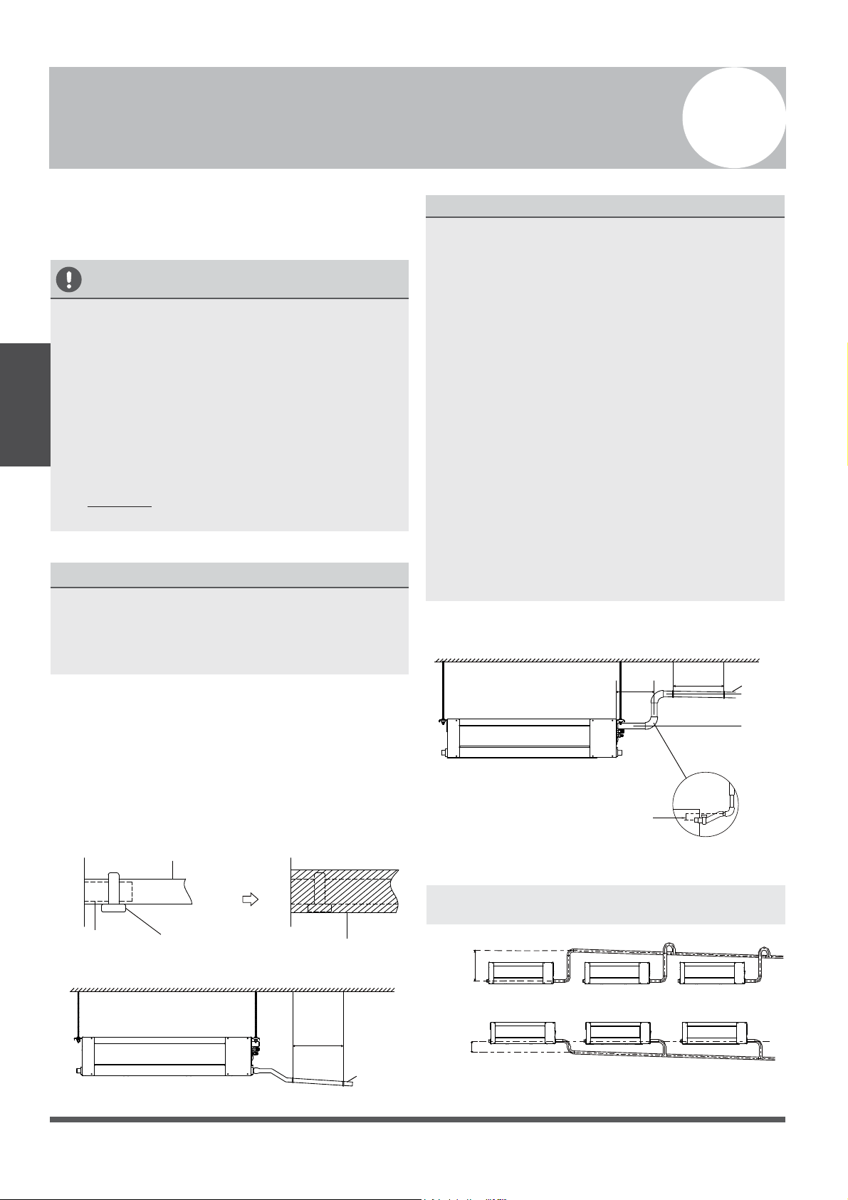
Fig. 6.3
(39-59”)
(8”)
<20cm
(21.7”)
<55cm
Lean over 1/50
1-1.5m
Drainpipe installation, for units with a pump
Ceiling
0 - 75mm
(3”)
NOTE ON DRAINPIPE INSTALLATION
•
When using an extended drainpipe, tighten
the indoor connection with an additional
protection tube. This prevents it from
pulling loose.
• The drainpipe should slope downward at a
gradient of at least 1/100, to prevent water
from flowing back into the air conditioner.
• To prevent the pipe from sagging, space
hanging wires every 1-1.5m (39-59”).
• If the outlet of the drainpipe is higher than
the body’s pump joint, provide a lift pipe for
the exhaust outlet of the indoor unit. The
lift pipe must be installed no higher than
55cm (21.7”) from the ceiling board. the
distance between the unit and the lift pipe
must be less than 20cm (7.9”). Incorrect
installation could cause water to flow back
into the unit and flood.
The drainpipe is used to drain water away from
the unit. Improper installation may cause unit
and property damage.
CAUTION
•
Insulate all piping to prevent condensation,
which could lead to water damage.
• If the drainpipe is bent, or installed
incorrectly, water may leak and cause a
water-level switch malfunction.
• In HEAT mode, the outdoor unit will
discharge water. Ensure that the drain hose
is placed in an appropriate area, to avoid
water damage and slippage.
• DO NOT pull on the drainpipe forcefully. This
could disconnect it and cause damage.
NOTE ON PURCHASING PIPES
Installation requires a polyethylene tube
(exterior diameter = 3.7-3.9cm, interior diameter
= 3.2cm), which can be obtained at your local
hardware store or dealer.
Indoor Drainpipe Installation
Install the drainpipe as illustrated in Figure 6.2.
1.
2.
Drainpipe
Connecting Port
Drain Hose
Pipe Clasp
Insulation
Fig. 6.1
Drainpipe Installation
Fig. 6.2
6
Drainpipe
Installation
Cover the drainpipe with heat insulation, to
prevent condensation and leakage.
Attach the mouth of the drain hose to the
unit’s outlet pipe. Sheath the mouth of the
hose, and clip it rmly with a pipe clasp.
(See Fig 6.1)
NOTE: When connecting multiple drainpipes,
install the pipes as illustrated in Fig 6.4.
(39-59”)
1-1.5m
Lean over 1/50
Ceiling
• To prevent air bubbles, keep the drain hose
level, or slightly tiled up (<75mm / 3”).
0-53cm
(20.8”)
≥10cm
(4”)
Fig. 6.4
Page 16
Drainage Test
Check that the drainpipe is unhindered.
This test should be performed on newly built
houses, before the ceiling is paved.
Units WITH a Pump.
Units WITHOUT a Pump
1. Remove the test cover.
Fill the water pan with 2 liters of water.
2. Turn on the unit, in COOLING mode. You will
hear the drain pump work . Check whether the
water is discharged properly (a 1-minute lag
is possible, depending on the length of the
drain pipe), Check whether water leaks from
the joints.
3. Turn o the air conditioner, and put the cap
back on.
3. Using a 65-mm (2.5”) core drill, drill a hole into
the wall. Be sure that the hole is drilled at
a slightly downward angle, so that the outdoor
end of the hole is lower than the indoor end
by about 12-mm (0.5”). This will ensure proper
water drainage (See Fig. 6.5). Place the
protective wall cu into the hole. This protects
the edges of the hole, and will help seal it
once installation is completed.
Wall
IndoorOutdoor
≈ 12mm / 0.5 inch
Fig. 6.5
NOTE: When drilling the hole, be sure to
avoid wires, plumbing, and other sensitive
components.
4. Pass the drain hose through the wall hole.
Make sure the water drains to a safe location
where it will not cause water damage, or a
slipping hazard.
NOTE: The drainpipe outlet should be at least
5cm (1.9”) above the ground. If it touches the
ground, the unit may become blocked, and
malfunction. If you discharge the water directly
into a sewer, make sure that the drain has a U
or S pipe, to catch odors that might otherwise
come back into the house.
Drainpipe
Installation
Test cap
Fig.6.7
Fig.6.8
C
L
O
S
E
D
O
P
E
N
C
L
O
S
E
D
O
P
E
N
Stow tube
Fig.6.6
Stow tube
Fill the water pan with 2 liters of water.
Check that the drainpipe is unhindered.
Page 17
Refrigerant Piping Connection
Safety Precautions
WARNING
• All eld piping must be completed by a
licensed technician, and must comply with
all relevant local and national regulations.
• When the air conditioner is installed in a
small room, measures must be taken to
prevent the refrigerant concentration in
the room from exceeding the safety limit,
in the event of refrigerant leakage. If the
refrigerant leaks, and its concentration
exceeds its proper limit, hazards due to
lack of oxygen may result.
• When installing the refrigeration system,
ensure that air, dust, moisture, or foreign
substances do not enter the refrigerant
circuit. Contamination in the system may
cause poor operating capacity, high
pressure in the refrigeration cycle,
explosion, or injury.
• Ventilate the area immediately if there is
refrigerant leakage during the installation.
Leaked refrigerant gas is both toxic and
flammable. Ensure there is no refrigerant
leakage after completing the installation
work.
Notes On Pipe Length and Elevation
Ensure that the length of the refrigerant pipe, the
number of bends, and the drop height between
the indoor and outdoor units meets the
requirements shown in Table 7.1:
Table 7.1: The Maximum Length And Drop
Height, Based on Models. (Unit: m/ft.)
Type of Model Capacity
(Btu/h)
Length of
Piping
Maximum Drop
Height
North America,
Australia and the
EU Models
Inverter Split
Ty p e
<15K 25/82 10/33
15K - <24K 30/100 20/66
24K - <36K 50/164 25/82
36K - 60K 65/213 30/100
Other Split Type
12K 15/49 8/26
18K-24K 25/82 15/49
30K-36K 30/98.4 20/66
42K-60K 50/164 30/100
7
Refrigerant Piping
Connection
Page 18
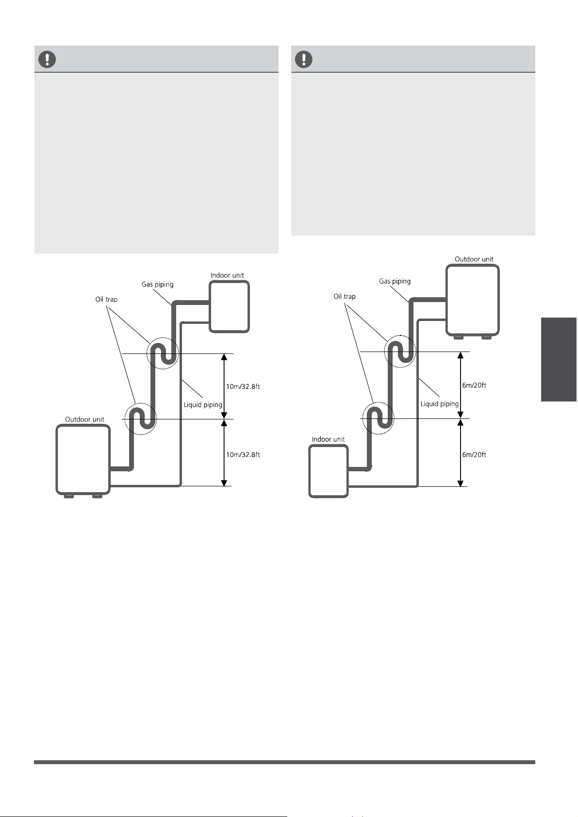
Fig. 7.2 Fig. 7.3
Refrigerant Piping
Connection
Oil traps
CAUTION
•
When the indoor unit is installed higher than
the outdoor unit:
An oil trap should be installed every 10m
(32.8ft) of vertical suction line riser.
(See Fig. 7.2)
-If oil flows back into the outdoor unit’s
compressor, this might cause liquid
compression, or deterioration of oil return.
Oil traps in the rising gas piping can prevent
this.
CAUTION
The indoor unit is installed higher than the
outdoor unit
When the outdoor unit is installed higher than
the indoor unit:
-It is recommended that vertical suction risers
not be upsized. Proper oil return to the
compressor should be maintained with suction
gas velocity. If velocities drop below 7.6 m/s
(1500 fpm (feet per minute)), oil return will be
decreased. An oil trap should be installed every
6m (20ft) of vertical suction line riser.
(See Fig. 7.3)
The outdoor unit is installed higher than the
indoor unit
Page 19
•
•
Pipe
Reamer
Point down
Fig. 7.5
Table 7.2
Permitted length
Piping
Length
Total Piping length 18K+18K 30m/98’ L+Max
(L1, L2)
24K+24K
30K+30K
50m/164’
(farthest distance from
the line pipe branch)
15m/50’ L1, L2
(farthest distance from
the line pipe branch)
10m/33’ L1-L2
Drop
Height
Drop height between
indoor and outdoor unit
20m/66’ H1
Drop height between
two indoor units
0.5m/1.5’ H2
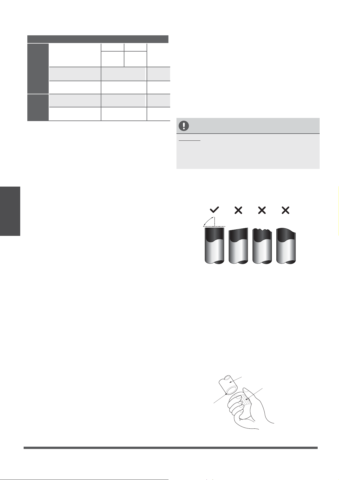
CAUTION
DO NOT deform pipe while cutting. Be extra
careful not to damage, dent, or deform the pipe
while cutting. This will drastically reduce the
heating efficiency of the unit.
1. Ensure that the pipe is cut at a perfect
90° angle. Refer to Fig. 7.4 for examples
of bad cuts.
Oblique
Rough
Warped
90°
Fig. 7.4
Step 2: Remove burrs
Burrs can aect the air-tight seal of the refrigerant
piping connection. They must be completely
removed.
1. Hold the pipe at a downward angle, to
prevent burrs from falling into the pipe.
2. Using a reamer or deburring tool, remove
all burrs from the cut section of the pipe.
Refrigerant Piping
Connection
Step 1: Cut pipes
When preparing refrigerant pipes, take extra
care to cut and flare them properly. This will
ensure efficient operation, and minimize the
need for future maintenance.
1. Measure the distance between the indoor
and outdoor units.
2. Using a pipe cutter, cut the pipe a bit
longer than the measured distance.
Page 20

Step 3: Flare Pipe Ends
Proper flaring is essential in achieving an
airtight seal.
1. After removing burrs from the cut pipe, seal
the ends with PVC tape, to prevent foreign
materials from entering into the pipe.
2.
Sheath the pipe with insulating material.
3.
Place flare nuts on both ends of pipe.
Make sure that they are facing the correct
direction, because they cannot be put on
or have their direction changed after flaring.
See Fig. 7.6
Flare Nut
Copper Pipe
Fig. 7.6
4. Remove PVC tape from pipe ends when
ready to perform flaring work.
Refrigerant Piping
Connection
5. Clamp flare form onto the end of the pipe.
The end of the pipe must extend beyond
the flare form.
Flare Form
Pipe
Fig. 7.7
6.
Place flaring tool onto the form.
7.
Turn the handle of the flaring tool
clockwise until the pipe is fully flared.
Flare the pipe in accordance with the
dimensions shown in Table 7.5.
8.
Remove the flaring tool and flare form, and
inspect the end of the pipe for cracks and for
even flaring.
Step 4: Connect the Pipes
First connect the copper pipes to the indoor unit,
then connect it to the outdoor unit. You should
first connect the low-pressure pipe, then the high-
pressure pipe.
1.
When connecting the flare nuts, apply a thin
coat of refrigeration oil to the flared ends of
the pipes.
2.
Align the center of the two pipes that you
will connect.
Indoor Unit Tubing
Flare Nut
Pipe
Fig. 7.9
3. Tighten the flare nut as tightly as possible by hand.
4. Using a spanner, grip the nut on the unit tubing.
5. While firmly gripping the nut, use a torque
wrench to tighten the flare nut, according to
the torque values in Table 7.5.
Page 21
PIPING EXTENSION BEYOND FLARE FORM
Pipe
Gauge
Tightening
Torque
Flare Dimension (A)
(Unit: mm/Inch)
Flare Shape
Min. Max .
Ø 1/4
14.2-17.2 N.m
(10.5 - 12.5 Lb.Ft.)
8.3/0.3 8.3/0.3
R0.4~0. 8
45
°
±
2
90
°
±
4
A
Fig. 7.6
Ø 3/8
32.7-39.9 N.m
(24 - 30 Lb.Ft.)
12.4/0.5 12.4/0.5
Ø 1/2
49.5-60.3 N.m
(36 - 45 Lb.Ft.)
15.4/0.6 15.8/0.6
Ø 5/8
61.8-75.4 N.m
(45 - 52 Lb.Ft.)
18.6/0.7 19/0.74
Ø 3/4
97.2-118.6 N.m
(72 - 88 Lb.Ft.) 22.9/0.9 23.3/0.9
Ø 7/8
109.5-133.7 N.m
(81 - 102 Lb.Ft.) 27/1.06 27.3/1.07
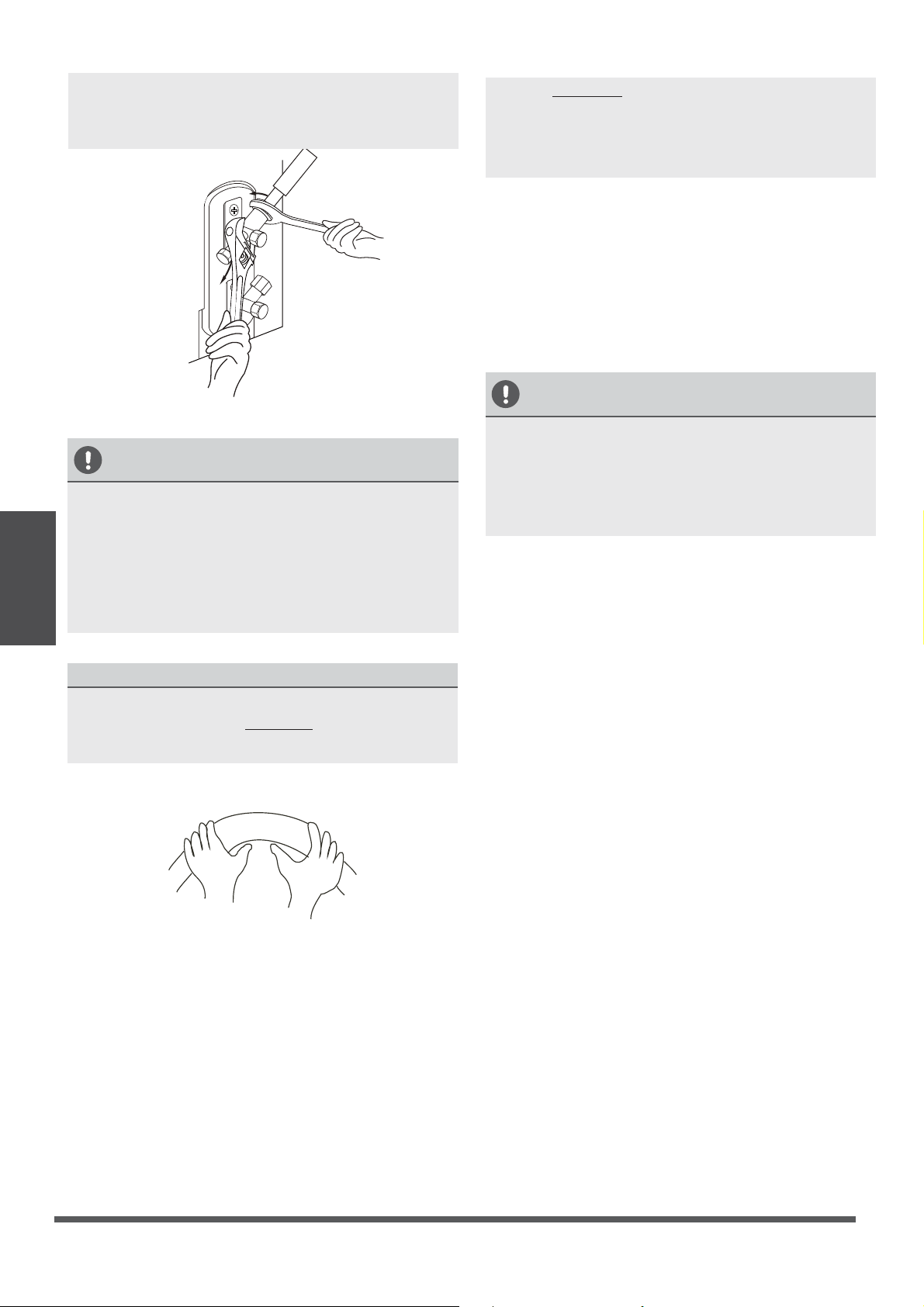
NOTE: Use both a spanner and a torque wrench
when connecting or disconnecting pipes to/from
the unit.
Fig. 7.10
CAUTION
• Be sure to wrap insulation around the piping.
Direct contact with the bare piping may result
in burns or frostbite.
• Make sure the pipe is properly connected.
Over tightening may damage the bell mouth,
and under tightening may lead to leakage.
NOTE ON MINIMUM BEND RADIUS
Carefully bend the tubing in the middle according
to the diagram below. DO NOT bend the tubing
more than 90°, or more than 3 times.
Bend the pipe using thumbs
min-radius 10cm (~4”)
Fig. 7.11
6. After connecting the copper pipes to the
indoor unit, wrap the power cable, signal
cable, and the piping together using binding
tape.
NOTE:
DO NOT intertwine signal cable with
other wires. While bundling these items
together, do not intertwine or cross the signal
cable with any other wiring.
7. Thread this pipeline through the wall and
connect it to the outdoor unit.
8. Insulate all the piping, including the valves
of the outdoor unit.
9. Open the stop valves of the outdoor unit
to start the flow of the refrigerant
between the indoor and outdoor unit.
CAUTION
Check to make sure there is no refrigerant leak
after completing the installation work. If there is
a refrigerant leak, ventilate the area immediately
and evacuate the system (refer to the Air
Evacuation section of this manual).
Refrigerant Piping
Connection
Page 22
TAKE NOTE OF FUSE SPECIFICATIONS
The air conditioner’s printed circuit board (PCB)
is designed with a fuse that provides overcurrent
protection. The specications of the fuse are
printed on the circuit board, examples of such
are T5A/250VAC and T10A/250VAC.
Wiring
Safety Precautions
WARNING
•
Disconnect the power supply before doing
work on the unit.
• All wiring must be performed according to
all relevant local and national regulations.
• Wiring must be done by a qualied
technician. Improper connections may
cause electrical malfunction, injury, or re.
• An independent circuit and single outlet
must be used for this unit.
DO NOT plug another appliance or
charger into the same outlet. If it cannot
handle the load or there is a defect in the
wiring, it can lead to shock, re, and unit
and property damage.
• Connect the power cable to the terminals
and fasten it with a clamp. An unsecure
connection may cause fire.
• Make sure that all wiring is done correctly
and that the control board cover is properly
installed. Failure to do so can cause
overheating at the connection points, fire,
and electrical shock.
•
Ensure that main power supply connection
is made through a switch that disconnects
all poles, with a contact gap of at least 3mm
(0.12”).
• DO NOT modify the length of the power
cord, or use an extension cord.
CAUTION
• Connect the outdoor wires before
connecting the indoor wires.
• Make sure you ground the unit. The
grounding wire should be located away
from gas pipes, water pipes, lightning rods,
telephone wires or other grounding wires.
Improper grounding may cause electrical
shock.
• DO NOT connect the unit to the power
source until all wiring and piping is
completed.
•
Make sure that you do not cross your
electrical wiring with your signal wiring.
This may cause distortion and interference.
To prevent distortion when the compressor starts
(you can nd the unit’s power information on
the rating sticker),:
• The unit must be connected to the main
outlet. Normally, the power supply must
have an impedance of 32 ohms.
• No other equipment should be connected
to the same power circuit.
Outdoor Unit Wiring
WARNING
Before performing any electrical or wiring work,
turn o the main power to the system.
1. Prepare the cable for connection
a. You must first choose the right cable size.
Be sure to use H07RN-F cables.
Table 8.1: Minimum Cross-Sectional Areas
of Power and Signal Cables in North
America
Rated Current of
Appliance (A)
AWG
718
7 - 13 16
13 - 18 14
18 - 25 12
25 - 30 10
8
Wiring
Page 23
b. Using wire strippers, strip the rubber jacket
from both ends of the signal cable to reveal
approximately 15cm (~6”) of wire.
c.
Strip the insulation from the ends.
d. Using a wire crimper, crimp u-lugs onto the
ends.
NOTE: When connecting the wires, strictly
follow the wiring diagram found inside the
electrical box cover.
2. Remove the electric cover of the outdoor unit.
If there is no cover on the outdoor unit, take
o the bolts from the maintenance board and
remove the protection board.
(See Fig. 8.1, 8.2)
Cover
Screw
Fig. 8.1
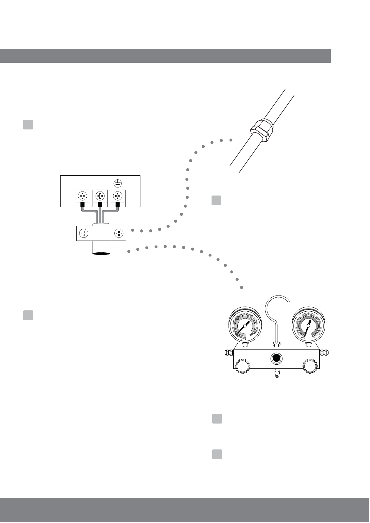
3. Connect the u-lugs to the terminals.
Match the wire colors/labels with the labels
on the terminal block, and rmly screw the u-lug
of each wire to its corresponding terminal.
4. Clamp down the cable using the cable clamp.
5.
Insulate unused wires with electrical tape.
Keep them away from any electrical or metal
parts.
6. Reinstall the cover of the electric control box.
Indoor Unit Wiring
1. Prepare the cable for connection
a. Using wire strippers, strip the rubber jacket
from both ends of the signal cable to reveal
about 15cm (~6”) of the wire.
b. Strip the insulation from the ends of the
wires.
c. Using a wire crimper, crimp the u-lugs onto
the ends of the wires.
Wiring
2. Remove the cover of the electric control box
on your indoor unit.
3. Connect the u-lugs to the terminals.
Match the wire colors/labels with the labels
on the terminal block, and rmly screw the u-lug
of each wire to its corresponding terminal.
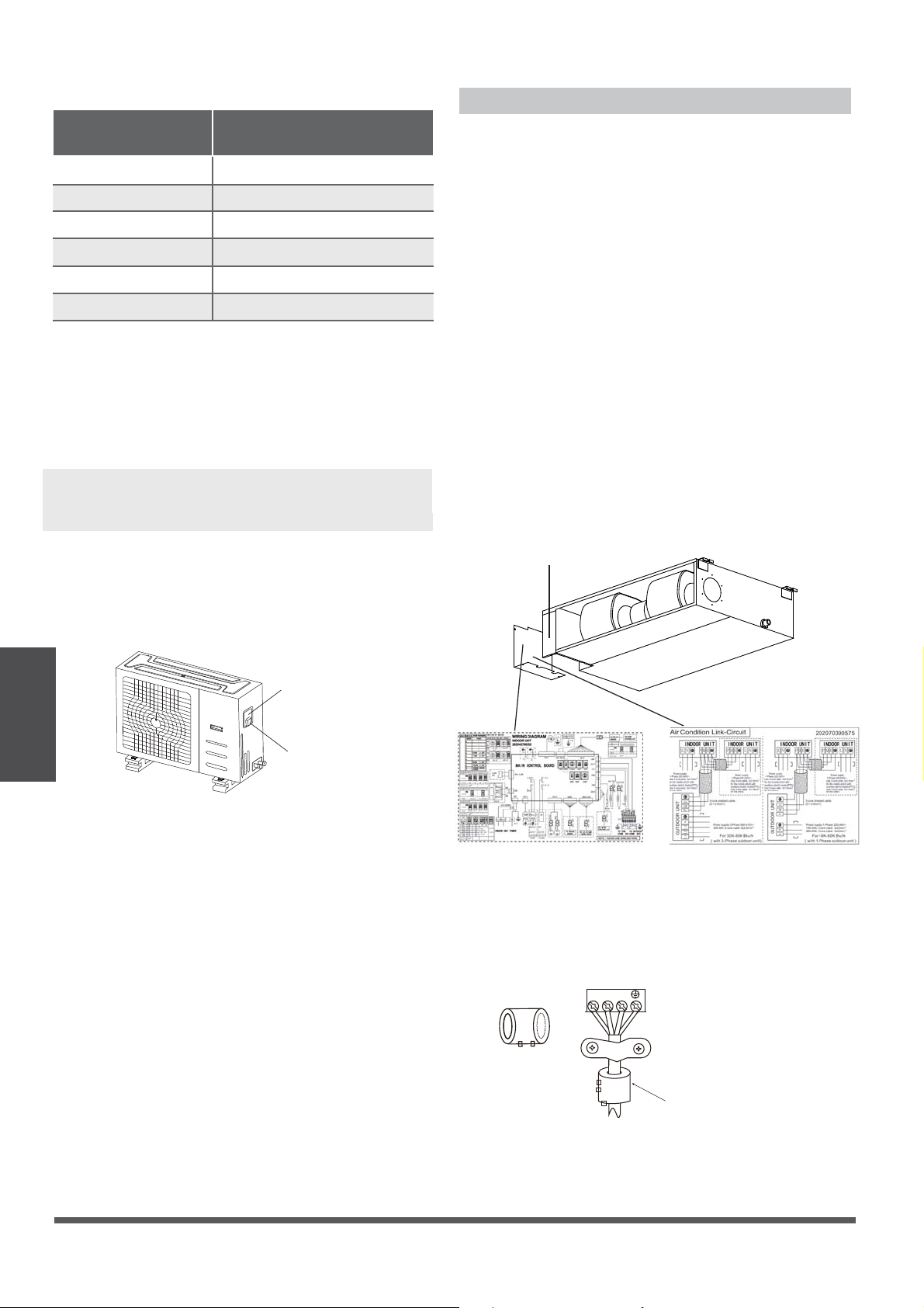
Refer to the serial number and wiring
diagram located on the cover of the electric
control box.
Connective Wiring Diagram
Wiring Diagram
Control Box
Fig. 8.3
Table 8.2: Other World Regions
Rated Current of
Appliance (A)
Area (mm²)
Nominal Cross-Sectional
60.75
6 - 10 1
10 - 16 1.5
16 - 25 2.5
25- 32 4
32 - 45 6
Page 24
Fig. 8.4
Magnetic Ring
(if supplied and packed with the accessories)
1 2 3
Pass the belt through
the hole of the Magnetic
ring to fix it onto the cable
Wiring
CAUTION
• While connecting the wires, please follow
the wiring diagram strictly.
• The refrigerant circuit can become very
hot. Keep the interconnection cable away
from the copper tube.
4. Clamp down the cable with the cable clamp.
The cable must not be loose or tug on the
u-lugs.
5. Reattach the electric box cover.
Using the wire controller to set external
static pressure (some models):
You can use the unit’s automatic airow
adjustment function to set external static
pressure.
Automatic airow adjustment is the volume
of blow-o air that has been automatically
adjusted to the quantity rated.
1. Make sure the test run is done with a dry
coil. If the coil is not dry, run the unit for 2
hours in FAN-ONLY mode to dry the coil.
2. Check that both the power supply wiring and
duct installation have been completed
Check that any closing dampers are open.
Check that the air lter is properly attached
to the air suction side passage of the unit.
3. If there is more than one air inlet and outlet,
adjust the dampers so that the airow rate
of each air inlet and outlet conforms with
the designed airow rate. Make sure the
unit is in FAN-ONLY mode. Press and set
the airow adjustment button on the
remote control to change the airow rate
from H or L.
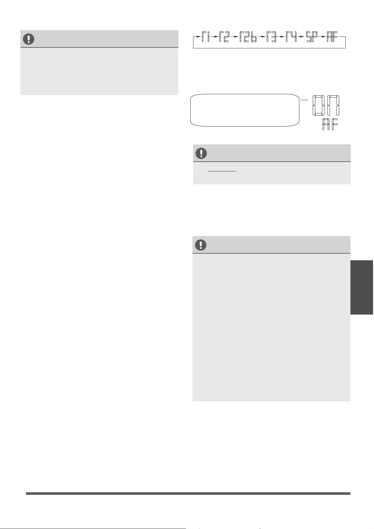
4. Set the parameters for automatic airow
adjustment. When the air conditioning unit
is o, perform the follwoing steps:
- Press “COPY”.
- Press “+” or “-” to select the AF.
- Press “CONFIRM”. The air conditioning
unit will then start the fan for automatic
airow adjustment.
ON will ash when the fan
is on during automatic
airow adjustment.
After 3 to 6 minutes, the air conditioning
unit will stop operating, once automatic airow
adjustment has nished.
•
•
CAUTION
• DO NOT adjust the dampers when
automatic airow adjustment is active.
CAUTION
• If there is no change after airow
adjustment in the ventilation paths, be sure
to reset the automatic airow adjustment.
• If there is no change to ventilation paths
after airow adjustment, contact your dealer,
especially if this occurs after testing the
outdoor unit, or if the unit has been moved
to a dierent location.
• Don’t use automatic airow adjustment with
the remote control if you are using booster
fans, outdoor air processing units, or an HRV
via duct.
• If the ventilation paths have been changed,
reset airow automatic adjustment as
described from step 3 onwards.
Page 25
Page 26
Air Evacuation
9
Preparations and Precautions
can cause abnormal rises in pressure, which
can damage the air conditioner, reduce its
efficiency, and cause injury. Use a vacuum pump
and manifold gauge to evacuate the line set and the
indoor unit, removing any non-condensable gas
and moisture from the system.
Evacuation should be performed upon initial
installation, and when the unit is relocated.
BEFORE PERFORMING EVACUATION
Check to make sure that both LIQUID
SIDE and GAS SIDE pipes between
the indoor and outdoor units are
connected properly, in accordance with the
Refrigerant Piping Connection section of
this manual.
Check to make sure all wiring is connected
properly.
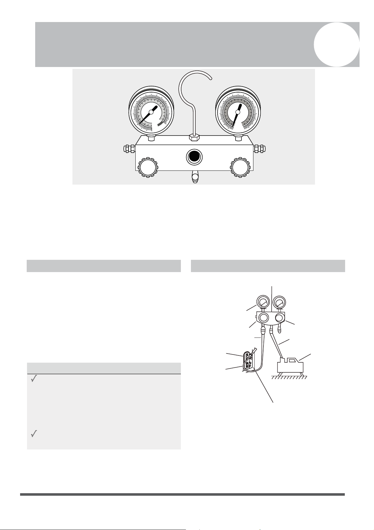
Evacuation Instructions
Before using the manifold gauge and vacuum
pump, read their operation manuals to familiarize
yourself with how to use them properly.
Manifold Gauge
Low Pressure Gauge
-76cmHg
L
ow Pressure Valve
High Pressure
Valve
Blue (Low) Hose
Yellow (Middle) Hose
Vacuum
Pump
High Pressure Gauge
Outdoor Unit Service Valve Set (GAS and LIQUID Valves)
1.
Connect the blue (low side) hose of the manifold
gauge to the service port on the outdoor unit’s
GAS SIDE valve (use a 1/4” to 5/16” port adapter if
needed, which is sold separately)
2.
Connect the yellow (middle or common ) hose from
the manifold gauge to the vacuum pump.
MC MC
Fig. 6.1
Air and foreign matter in the refrigerant circuit
BLUE (Low Pressure) Side of Manifold Gauge RED (High Pressure) Side of Manifold Gauge
YELLOW (Common) Side of Manifold Gauge
BLUE (Low Pressure) Gauge RED (High Pressure) Gauge
Low Pressure Valve High Pressure Valve
LARGE DIA (GAS)
Service Valve
SMALL DIA (LIQUID)
Service Valve
Caution: Systems are precharged with refrigerant (entire amount necessary for the system set has been
charged into the outdoor section). The line sets and the indoor units are not charged, and must be evacuated
prior to releasing the refrigerant from the outdoor unit to the rest of the system.
Do NOT open the valves of the 2 service ports on your outdoor unit until the air evacuation is completed
successfully, and thw system passes leak checks. BOTH of those Service valves MUST BE OPENED to release the
refrigerant before turning the system ON. Operating the system with service valves closed will result in
compressor damage.
Page 27
Air Evacuation
3.
Open the BLUE (Low Pressure) valve of the manifold
Gauge. Keep the RED (High Pressure) Valve closed.
4.
Turn the vacuum pump ON to start evacuating the
air from the line set and indoor unit circuits.
5.
Run the vacuum pump for at least 15 minutes, or
until the Low Pressure Gauge reads -76cmHG
(-100 kPa or -30 in Hg) (negative value).
6.
Close the Blue (Low Pressure) Valve of the Manifold
Gauge, then turn the vacuum pump OFF.
7.
Wait for 5 minutes, then check that there has
been no rise in the Low Pressure Gauge reading.
8.
If there is a rise (Vacuum Loss), refer to the
Gas Leak Check section for information
on how to check for leaks. If there is no
change in vacuum reading, unscrew the cap
from the LIQUID Side Service Valve (Fig. 6.2)
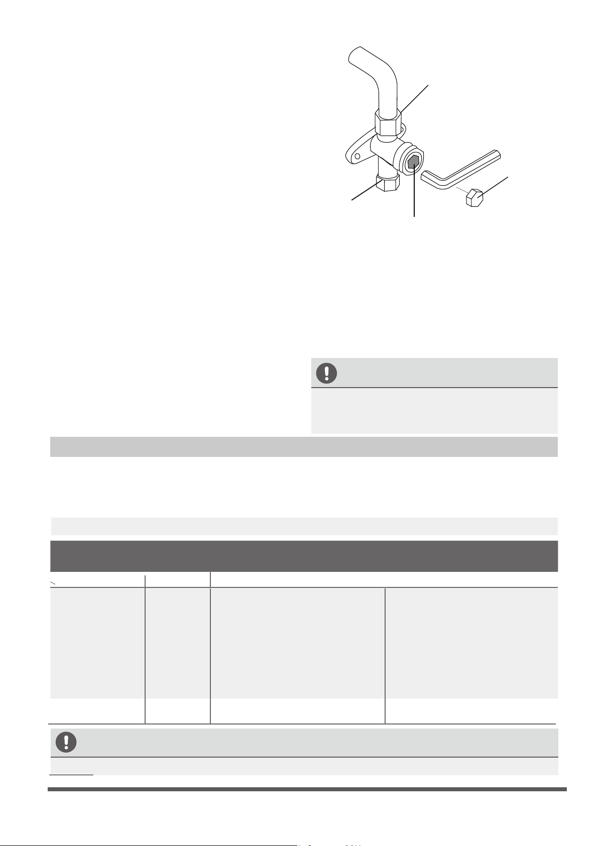
9.
Insert a hexagonal wrench into the service valve
(LIQUID Side Valve), and open the valve by
turning the wrench for a 1/4 counterclockwise
turn. Listen for the sound of gas exiting the
system, then close the valve after 5 seconds.
10.
Watch the Pressure Gauge for a few minutes,
to make sure that there is no drop in the
pressure value (indicating a leak)
The Low Pressure Gauge should now show
a positive pressure value (above zero).
Flare Nut
Hexagonal
Dust Cap
Valve Core
11.
Remove the charging hose from the service port.
12.
Using a hexagonal wrench, fully open both the
LIQUID side and GAS side service valves.
13.
Tighten the valve caps on all three valves (service
port, liquid side, gas side) by hand.
Then tighten it further, using a torque
wrench, if needed.
OPEN VALVE STEMS GENTLY
When opening valve stems, turn the hexagonal
wrench until it seats against the stopper. Do not
try to force the valve to open further.
Note on Adding Refrigerant
ADDITIONAL REFRIGERANT PER PIPE LENGTH
Connective Pipe
Length (m)
Air Purging
Method
Additional Refrigerant
< Standard pipe length Vacuum Pump N/A
> Standard pipe
length (5m/16ft)
Vacuum Pump
Liquid Side: Ø 6.35 (ø 1/4”)
Gas side either
Ø 9.52 (ø 3/8”) or
Ø 12.7 (ø 1/2”)
CAUTION
DO NOT mix refrigerant types. Use only the same type of refrigerant (R410a).
Fig. 6.2
Liquid Side: Ø 9.52 (ø 3/8”)
Gas side either
Ø 15.87 (ø 5/8”) or
Ø 19.05 (ø 3/4”)
Copper Pipe from Indoor Unit
Service Port
(Only the GAS Side
Valve has this port)
Some systems require additional charging, depending on pipe lengths. The pipe length varies according
to locations of the indoor and outdoor units. The system has been factory charged with sucient R410a
refrigerant for the standard pipe length of 5m (~16‘). The additional refrigerant to be charged can be
calculated using the following formula. This is only necessary if the length exceeds 7.5m (~25 feet).
Default charge has tolerance up to 25ft,
for lengths beyond 25ft (7.6m), add:
15 g/m x each additional meter after 5m
0.16 oz/ft x each additional foot after 16ft
Default charge has tolerance up to 25ft,
for lengths beyond 25ft (7.6m), add:
30 g/m x each additional meter after 5m
0.32 oz/ft x each additional foot after 16ft
Page 28
Test Run
Before the Test Run
A test run must be performed after the entire
system has been fully installed. Confirm
the following points prior to performing the test:
a) The indoor and outdoor units are properly
installed.
b) Piping and wiring are properly connected.
c) No obstacles are near the inlet and outlet of
the unit that might cause poor performance
or product malfunction.
d) The refrigeration system does not leak.
e) The drainage system is unimpeded and is
draining to a safe location.
f) The heating insulation is properly installed.
g) The grounding wires are properly connected.
h) The length of the piping and the additional
refrigerant stow capacity have been
recorded.
i) The power voltage is the correct voltage
for the air conditioner.
CAUTION
Failure to perform the test run may result in unit
damage, property damage, or personal injury.
Test Run Instructions
1. Open both the liquid and gas stop valves.
2. Turn on the main power switch, and allow the
unit to warm up.
3. Set the air conditioner to COOL mode.
4. For the Indoor Unit
a. Ensure the remote control and its buttons
work properly.
b. Ensure the louvers move properly and can
be changed by using the remote control.
c. Double check to see if the room
temperature is registered correctly.
d. Ensure that the indicators on the remote
control and the display panel on the indoor
unit work properly.
e. Ensure that the manual buttons on the indoor
unit work properly.
f. Check to see that the drainage system is
unimpeded, is and draining smoothly.
g. Ensure there is no vibration or abnormal
noise during operation.
5. For the Outdoor Unit
a. Check to see if the refrigeration system is
leaking.
b. Make sure that there is no vibration or
abnormal noise during operation.
c. Ensure that the wind, noise, and water
generated by the unit do not disturb your
neighbors, or pose a safety hazard.
6. Drainage Test
a. Ensure that the drainpipe flows smoothly.
New buildings should perform this test
before finishing the ceiling.
b. Remove the test cover. Add 2,000 ml of
water to the tank through the attached
tube.
c. Turn on the main power switch, and run
the air conditioner in COOL mode.
d. Listen to the sound of the drain pump to
see if it makes any unusual noises.
e. Check to see that the water has discharged.
It may take up to one minute before the
unit begins to drain, depending on the
drainpipe.
f. Make sure that there are no leaks in any of
the pipings.
g. Stop the air conditioner. Turn o the main
power switch, and reinstall the test cover.
NOTE: If the unit malfunctions or does not
operate according to your expectations, please
refer to the Troubleshooting section of the
Owner’s Manual before calling customer service.
Test Run
10

The design and specications are subject to change without prior notice for product
improvement. Consult with the sales agency or manufacturer for details.
QST2I-045AEN(I)
16123000000713
20171121
is a registered trademark of Parker Davis HVAC International, Inc.
Parker Davis HVAC International, Inc.
2250 NW 102 Place, Doral, FL 33172 - USA
Tel : (305) 513-4488
Fax : (305) 513-4499
email : info@pd-hvac.com
Website: www.pd-hvac.com
Copyright 2017, Parker Davis HVAC International, Inc., All rights reserved.