Loading ...
Loading ...
Loading ...
SuperiorFireplaces.us.com
126628-01_H
7
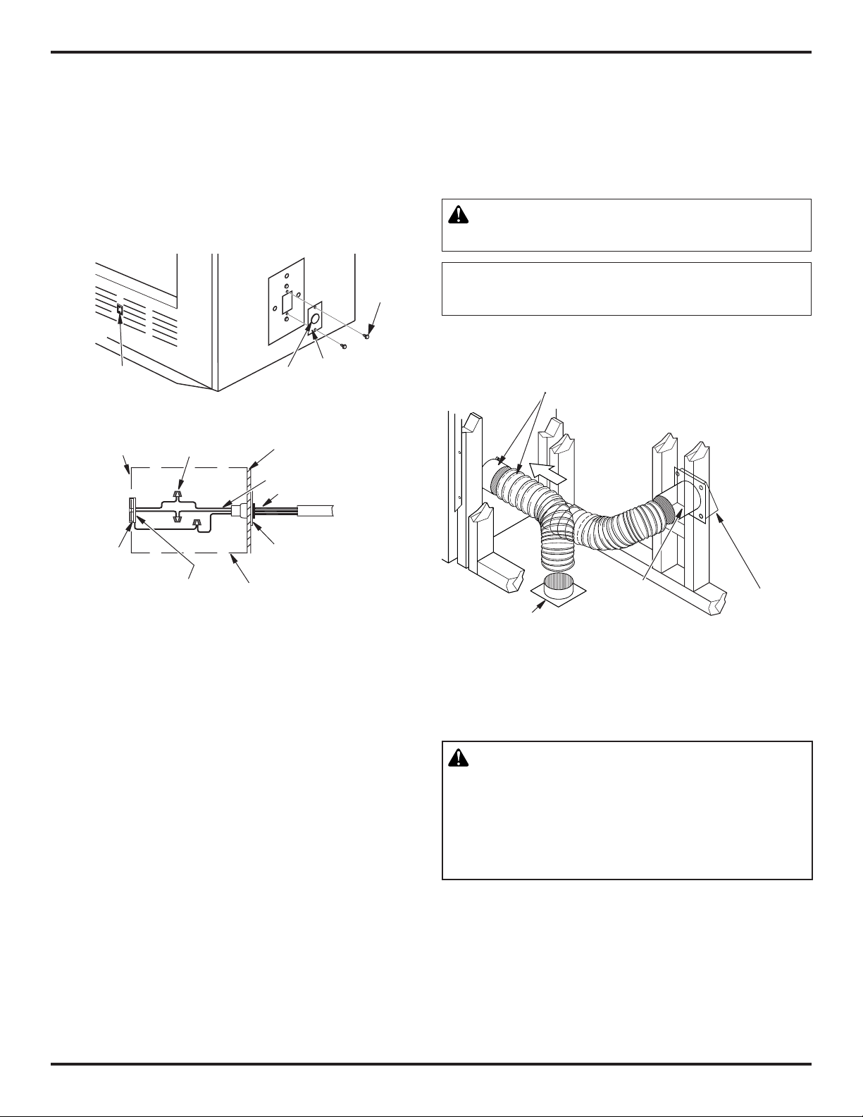
FAN/BLOWER KIT ASSEMBLY
Fan or blower kit is optional with this fireplace (for circulating models
only). Use of blowers or fans other than those manufactured by IHP
voids warranty. Fan is operated by pressing rocker switch (see Figure
6) in lower right hand corner of fireplace face. Blower is operated by
turning control knob (not shown).
Fan/blower kit electrical connections are made through electrical
cover plate on side of fireplace a shown in Figure 6.
FIREPLACE INSTALLATION Continued
Wiring Instructions
1. Remove electrical cover plate with bushing from fireplace by
removing 2 sheet metal screws as shown in Figure 6.
2. Slide power source wiring through electrical bushing opening
and electrical cover plate and make all necessary connections.
3. Slide all wiring connections in electrical housing as shown in
Figure 6.
4. Secure electrical cover plate with screws previously removed.
Note: Electrical housing and cover plate have sharp edges. Wear
protective gloves.
Electrical
Bushing
Electrical
Cover
Plate
Rocker
Switch
Figure 6 - Fan Switch-Electrical Bushing
Electrical
Housing
Wire Nut (3x)
(Not Supplied)
Outer Wrapper
of Fireplace
Electrical Cover Plate
and Electrical Bushing
Fireplace Chassis Ground
To Power
Source
Receptacle
(Supplied)
Power Source Wiring
(Not Supplied)
Pre-wired Receptacle
and Ground
Sheet
Metal
Screws
Figure 7 - Outside Air Kit
Secure to Collars with Metal Tape, Screws or
Straps Min. of ¼" x 20" (7 mm x 508 mm) in size
Air Inlet
Location
Must
Allow For
Bushes or
Snow
Vent Hood
Required
for Wall
Installation
Air Inlet
Eyebrow
Vented Crawl Space (Check
Local Codes Before Installing
in a Vented Crawl Space)
VENTING INSTALLATION
OPTIONAL OUTSIDE AIR KIT (MODEL AK4/AK4F)
Installation of outside air kit should be performed during rough fram-
ing of fireplace due to the nature of it's location. Outside combustion
air is accessed through a vented crawl space (AK4F) or through a
sidewall (AK4). See Figure 7 for instruction of operating air kit.
CAUTION: Combustion air inlet ducts shall not
terminate in attic space.
The maximum height for the air vent can not exceed
3 feet below the flue gas outlet of the termination.
CHIMNEY PIPE
WARNING: Label part number 900599-01 must
be applied by the installer to all chimney pipe
sections but is not required on sections that will
be visible after the installation is complete. Label
must wrap around the circumference of the pipe.
See accessories, page 20 for Kit F2659.
An IHP chimney system consists of 12", 18", 24", 36" and 48" snap-
lock, double-wall pipe segments, planned for maximum adaptability
to individual site requirements. Actual lengths gained after fitting
overlaps must be taken into consideration (lineal gain) and are given
in lineal gain chart (see Figure 8, page 8).
Lineal gain is actual measurable length of a part after two or more
parts are connected.
Loading ...
Loading ...
Loading ...