Loading ...
Loading ...
Loading ...
17
Operating Instructions and Owner’s ManualMr. Heater Series Heater
Outside Combustion Air Supply
TheMR.Heaterheaterisapprovedforinstallationwith
anoutsideairsupplysystem.Somecompoundssuchas
halogenatedhydrocarbonsorothercorrosivechemicalsinthe
aircanbedrawnintotheequipmentandcauseanaccelerated
rateofcorrosionofsomeoftheheatercomponents.Theuse
ofsuchchemicalcompoundsneartheenclosureshouldbe
avoided.
IMPORTANT: If the building has a slight negative
pressure or contaminants are present in the air, an
outside combustion air supply to the heaters is strongly
recommended.
Foranoutsideairsupply,afour(4”)inchO.D.singlewallpipe
maybeattachedtotheheater.Theductmaybeuptoforty-five
(30’)ft.maximumlengthortwo(2’)ft.minimumlengthwith
nomorethantwo(2)elbows.(SeeGeneralRequirementson
page15foradditionalinformation.)
Theairsupplyductmayhavetobeinsulatedtoprevent
condensationontheoutersurface.Theoutsideairterminal
shouldbesecurelyfastenedtotheoutsidewallbydrillingfour
(4)1/4”diameterholesintheoutsideflange;woodscrewsor
boltsandexpansionsleevesmaybeusedtofastenterminal.
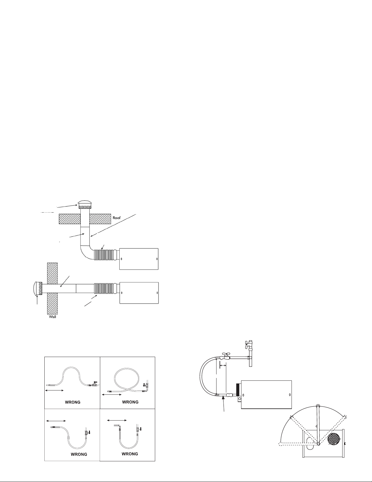
FIGURE 13: Non-Pressurized Outside Air Supply Duct
PVCPipe,“DryerHose”,orequivalentmaybeusedinsteadof
standardventpipe.
SECTION 6
Gas Piping
Readapplicablewarningsin(Section1)beforeproceedingwith
GasPipeinstallation.Improperinstallationmayresultinproperty
damage,severeinjury,ordeath.
Meterandservicemustbelargeenoughtohandlealltheburners
beinginstalledplusanyotherconnectedload.Thegaslinewhich
feedthesystemmustbelargeenoughtosupplytherequiredgas
withamaximumpressuredropof1/2”watercolumn.Whengas
pipingisnotincludedinthelayoutdrawing,thelocalgassupplier
willusuallyhelpinplanningthegaspiping.
A1/2”tappingateachburnerlocationmustbelocatedandoriented
asshownin(Figure14).Tochecksystempressure,putaplugged
1/8”NPTtappinginthegaslineattheconnectiontotheburner
farthestfromthesupply.Beforeconnectingtheburnerstothe
supplysystem,verifythatallhighpressuretestingofthegaspiping
hasbeencompleted.Donothighpressuretestthegaspipingwith
theburnersconnected.
Followtheseinstructionstoensureaprofessionalgassupply
installation:
• Supportallgaspipingwithsuitablepipehanging
materials.
• Usewroughtironorwroughtsteelpipeandmalleable
ironfitting.Allpipefittingsshouldbenewandfree
fromdefects.Carefullyreamthepipeandtubingends
toremoveobstructionsandburrs.
• UseL.P.gas-resistantjointcompoundonallpipe
threads.
• Checkthepipeandtubingendsforleaksbefore
placingheatingequipmentintoservice.When
checkingforgasleaks,usesoapandwatersolution:
NEVER USE AN OPEN FLAME.
Installtheflexgasconnectorasshown.Theflexgasconnector
accommodatesexpansionoftheheatingsystemandallowsforeasy
installationandserviceoftheburner.
FIGURE 14: Gas Line Connection with Stainless Steel Flex Gas
Connector
Shut-OffValvemustbeparallel
toburnergasinlet.The2”
displacementshownisforthecold
condition.Thisdisplacementmay
reducewhenthesystemisfired.
Shut–offValve
12 "
2"
1/2"StainlessSteelFlexGasConnector
Stk.#16401
90°
45°
0°
45°
4" (10 cm)
Seal All Joints
4"
Heater Movement
Heater Movement
Heater Movement
Heater Movement
Outside Air
Terminal
Flex Pipe
6" (15 cm) to
12" (30 cm) Long
Flex Pipe
6" (15 cm) to
12" (30 cm) Long
Flex Pipe
6" (15 cm) to
12" (30 cm) Long
Outside Air
Terminal
NOTE:
Flue pipe requires additional
support. Flex pipe will not
support riser and outside
air terminal
Vertical Outside Air
Horizontal Outside Air
FIGURE 14A: Incorrect Gas Line Connection with Stainless
Steel Flex Gas Connector
Loading ...
Loading ...
Loading ...