241-0355
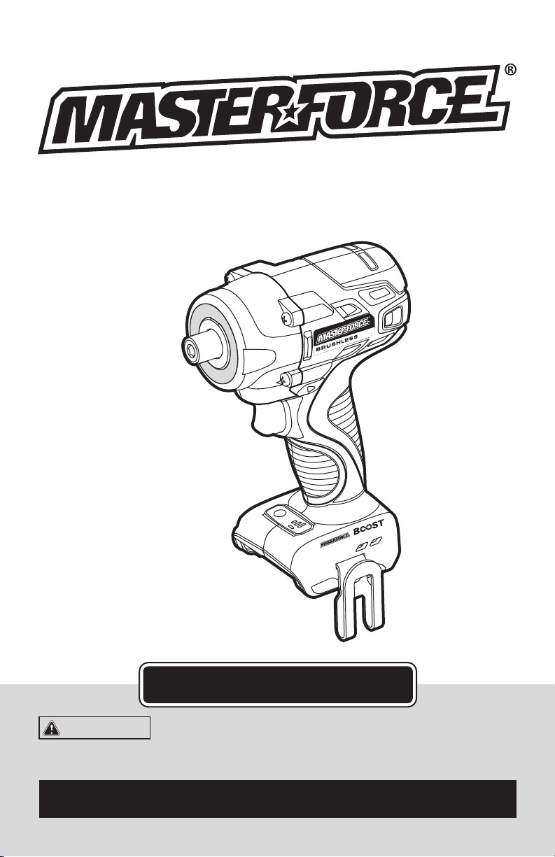
1/4” Impact Driver
OPERATOR’S MANUAL
CAUTION:
To Reduce the Risk of Injury, User Must
Read and Understand the Operator’s Manual. Save These
Instructions For Future Reference.
For questions / comments, technical assistance or repair parts –
Please Call Toll Free: 1-866-917-4374 (M-F 8:30am-5:00pm EST).

TABLE OF CONTENTS
Safety Symbols ......................................................... Page 2
Safety Instructions ...................................................... Page 3
Overview/Specications ................................................. Page 7
Assembly ............................................................. Page 8
Operation ............................................................. Page 9
Maintenance .......................................................... Page 13
Troubleshooting ....................................................... Page 14
Warranty .............................................................Page 15
Page 2
SAFETY SYMBOLS
Some of these following symbols may be used on this tool. Please study them and learn their
meaning. Proper interpretation of these symbols will allow you to operate the tool better and
more safely.
Symbol
Name
Designation / Explanation
V Volts Voltage
A Amperes Current
Hz Hertz Frequency (cycles per second)
W Watts Power
∿
Alternating current Type of current
�
Direct current Type or characteristic of current
n
o
No-load speed Rotational speed at no load
Class II construction Double insulated construction
.../min Per minute
Revolutions, strokes, surface speed
orbits, etc., per minute
Wear safety goggles
WARNING:
The operation of any
power tool can result in foreign objects
being thrown into your eyes, which can
result in severe eye damage. Before
beginning power tool operation, always
wear safety goggles or safety glasses
with side shields and a full-face shield
when needed. We recommend a Wide
Vision Safety Mask for use over eye-
glasses or standard safety glasses with
side shields. Always use eye protection
which is marked to comply with
ANSI Z87.1.
WARNING:
To ensure safety and reliability, all repairs should be performed by a
qualified service technician.
Page 3
SAFETY INSTRUCTIONS
The purpose of safety symbols is to attract your attention to possible dangers. The safety
symbols, and the explanations with them, deserve your careful attention and understand-
ing. The symbol warnings do not, by themselves, eliminate any danger. The instructions and
warnings they give are no substitutes for proper accident prevention measures.
WARNING:
Be sure to read and understand all safety instructions in this manual,
including all safety alert symbols such as “DANGER”, “WARNING” and “CAUTION” before
using this tool. Failure to following all instructions listed below may result in electric
shock, fire, and/or serious personal injury.
SYMBOL MEANING
SAFETY ALERT SYMBOL: Indicates DANGER, WARNING, OR CAUTION.
May be used in conjunction with other symbols or pictographs.
DANGER:
Indicates an imminently hazardous situation, which, if not avoided, will
result in death or serious injury.
WARNING:
Indicates a potentially hazardous situation, which, if not avoided,
could result in death or serious injury.
CAUTION:
Indicates a potentially hazardous situation, which, if not avoided, could
result in minor or moderate injury.
NOTICE: (Without Safety Alert Symbol) Indicates a situation that may result in property
damage.
SAVE THESE INSTRUCTIONS!

Page 4
SAFETY INSTRUCTIONS
GENERAL POWER TOOL SAFETY
WARNINGS
WARNING:
Read all safety
warnings, instruction, illustrations and
specifications provided with this power
tool.
Failure to follow all instructions listed below
may result in electric shock, re and/or seri-
ous injury.
Save all warnings and instructions for future
reference.
The term “power tool” in the warnings refers
to your mains-operated (corded) power tool
or battery-operated (cordless) power tool.
WORK AREA SAFETY
a) Keep work area clean and well lit.
Cluttered or dark areas invite accidents.
b) Do not operate power tools in explosive
atmospheres, such as in the presence of
flammable liquids, gases or dust. Power
tools create sparks which may ignite the
dust or fumes.
c) Keep children and bystanders away
while operating a power tool. Distractions
can cause you to lose control.
ELECTRICAL SAFETY
a) Power tool plugs must match the
outlet. Never modify the plug in any way.
Do not use any adapter plugs with earthed
(grounded) power tools. Unmodied plugs
and matching outlets will reduce risk of
electric shock.
b) Avoid body contact with earthed
or grounded surfaces, such as pipes,
radiators, ranges and refrigerators. There
is an increased risk of electric shock if your
body is earthed or grounded.
c) Do not expose power tools to rain or
wet conditions. Water entering a power
tool will increase the risk of electric shock.
d) Do not abuse the cord. Never use the
cord for carrying, pulling or unplugging
the power tool. Keep cord away from
heat, oil, sharp edges or moving parts.
Damaged or entangled cords increase the
risk of electric shock.
e) When operating a power tool outdoors,
use an extension cord suitable for outdoor
use. Use of a cord suitable for outdoor use
reduces the risk of electric shock.
f) If operating a power tool in a damp
location is unavoidable, use a ground fault
circuit interrupter (GFCI) protected supply.
Use of an GFCI reduces the risk of electric
shock.
PERSONAL SAFETY
a) Stay alert, watch what you are doing
and use common sense when operating a
power tool. Do not use a power tool while
you are tired or under the influence of
drugs, alcohol or medication. A moment of
inattention while operating power tools may
result in serious personal injury.
b) Use personal protective equipment.
Always wear eye protection. Protective
equipment such as a dust mask, non-skid
safety shoes, hard hat or hearing protection
used for appropriate conditions will reduce
personal injuries.
c) Prevent unintentional starting. Ensure
the switch is in the off-position before
connecting to power source and/or battery
pack, picking up or carrying the tool.
Carrying power tools with your nger on the
switch or energizing power tools that have
the switch on invites accidents.
d) Remove any adjusting key or wrench
before turning the power tool on. A wrench
or a key left attached to a rotating part of
the power tool may result in personal injury.
e) Do not overreach. Keep proper
footing and balance at all times. This
enables better control of the power tool in
unexpected situations.
f) Dress properly. Do not wear loose
clothing or jewelry. Keep your hair and

Page 5
SAFETY INSTRUCTIONS
clothing away from moving parts. Loose
clothes, jewelry or long hair can be caught
in moving parts.
g) If devices are provided for the
connection of dust extraction and
collection facilities, ensure these are
connected and properly used. Use of dust
collection can reduce dust-related hazards.
h) Do not let familiarity gained from
frequent use of tools allow you to become
complacent and ignore tool safety
principles. A careless action can cause
severe injury within a fraction of a second.
POWER TOOL USE AND CARE
a) Do not force the power tool. Use the
correct power tool for your application. The
correct power tool will do the job better and
safer at the rate for which it was designed.
b) Do not use the power tool if the switch
does not turn it on and off. Any power tool
that cannot be controlled with the switch is
dangerous and must be repaired.
c) Disconnect the plug from the power
source and/or remove the battery pack,
if detachable, from the power tool before
making any adjustments, changing
accessories, or storing power tools. Such
preventive safety measures reduce the risk
of starting the power tool accidentally.
d) Store idle power tools out of the reach
of children and do not allow persons
unfamiliar with the power tool or these
instructions to operate the power tool.
Power tools are dangerous in the hands of
untrained users.
e) Maintain power tools and accessories.
Check for misalignment or binding of
moving parts, breakage of parts and
any other condition that may affect the
power tool’s operation. If damaged, have
the power tool repaired before use. Many
accidents are caused by poorly maintained
power tools.
f) Keep cutting tools sharp and clean.
Properly maintained cutting tools with sharp
cutting edges are less likely to bind and are
easier to control.
g) Use the power tool, accessories
and tool bits etc. in accordance with
these instructions, taking into account
the working conditions and the work to
be performed. Use of the power tool for
operations different from those intended
could result in a hazardous situation.
h) Keep handles and grasping surfaces dry,
clean and free from oil and grease. Slippery
handles and grasping surfaces do not allow
for safe handling and control of the tool in
unexpected situations.
SERVICE
a) Have your power tool serviced by a
qualified repair person using only identical
replacement parts. This will ensure that the
safety of the power tool is maintained.
SPECIFIC SAFETY WARNINGS
a) Hold power tools by insulated gripping
surfaces when performing an operation
where the cutting tool may contact hidden
wiring. Contact with a” live” wire will make
exposed metal parts of the tool live and
shock the operator.
b) Take protective measures when
dust can develop during working that
is harmful to one’s health, combustible
or explosive. Example: Some dusts are
regarded as carcinogenic. Wear a dust
mask and work with dust/chip extraction
when connectable.
c) Secure the workpiece. A workpiece
clamped with clamping devices or in a vice
is held more secure than by hand.
d) To reduce the risk of electric shock or
damage to the charger and battery, use
only the batteries and charger listed.

Page 6
SAFETY INSTRUCTIONS
Battery pack Charger
252-8027
252-8029
252-8030
252-8031
252-8034
252-8035
252-8003
252-8005
252-8007
252-8025
252-8026
252-8037
WARNING:
Some dust created by
power sanding, sawing, grinding, drilling
and other construction activities contains
chemicals known to the state of California
to cause cancer, birth defects or other
reproductive harm. Some examples of
these chemicals are:
• Lead from lead-based paints
• Crystalline silica from bricks and cement
and other masonry products, and
• Arsenic and chromium from chemically-
treated lumber.
Your risk from these exposures varies,
depending on how often you do this type
of work. To reduce your exposure to these
chemicals: work in a well ventilated area,
and work with approved safety equipment,
such as those dust masks that are specially
designed to lter out microscopic particles.
Page 7
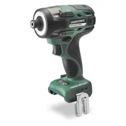
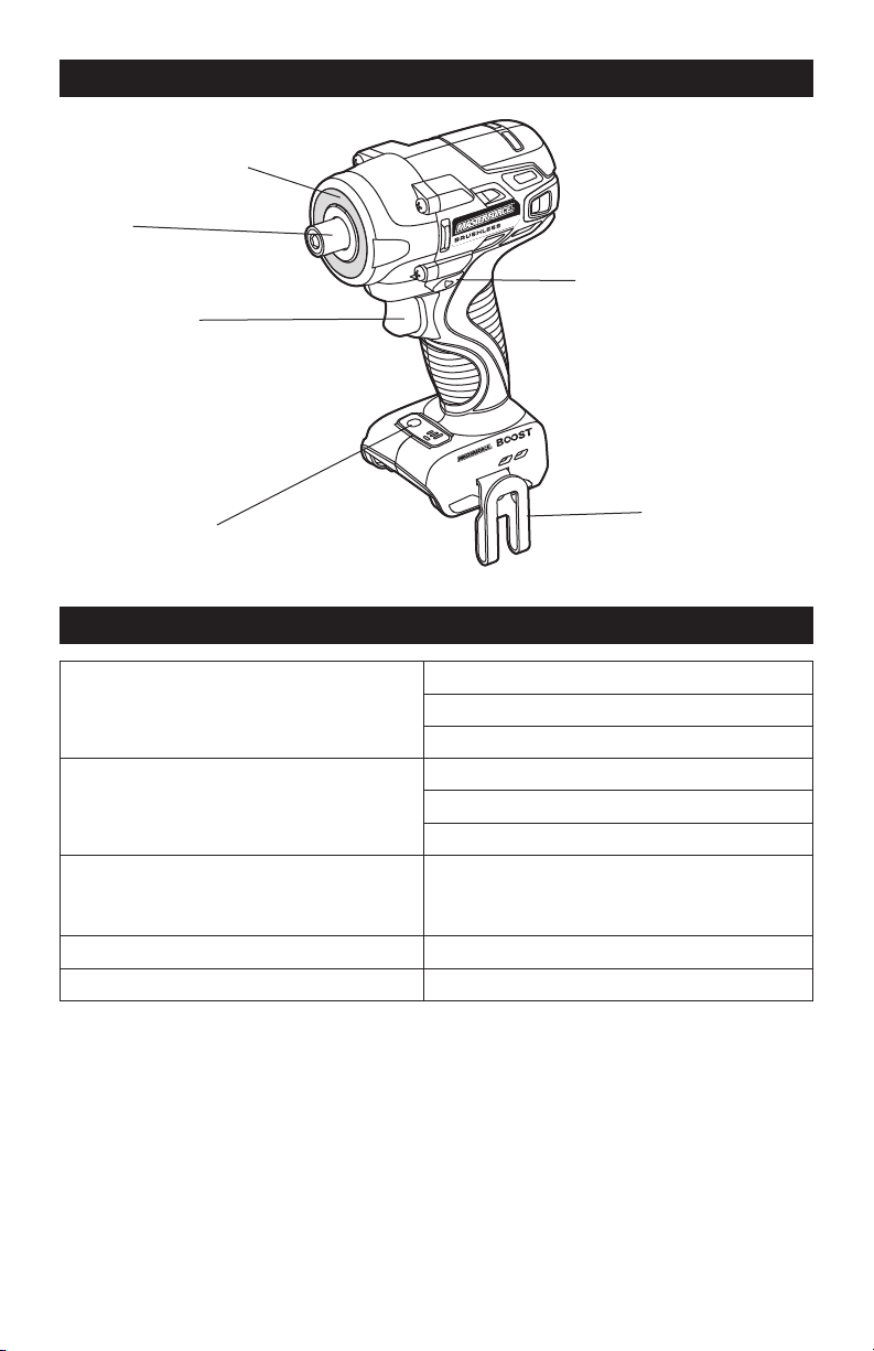
OVERVIEW
SPECIFICATIONS
No-load Speed I: 0-1,100 RPM
II: 0-2,000 RPM
III: 0-3,100 RPM
Impact Rate I: 0-1,250 BPM
II: 0-2,650 BPM
III: 0-3,500BPM
Torque I: 9,50 in.lb
II: 1,450 in.lb
III: 2,000 in.lb
Driver 1/4” Hex
Weight 2 lb. 14 oz (1.3 kg)
LED Worklight Ring
Mode-selector
Trigger Switch
Chuck
Direction-of-rotation
Selector
Belt Clip

Page 8
WARNING:
If any part is broken or
missing, DO NOT attach the battery pack
or operate the tool until the broken or
missing part is replaced. Failure to do so
could result in possible serious injury.
WARNING:
Do not attempt to
modify this tool or create accessories not
recommended for use with this tool. Any
such alteration or modification is misuse
and could result in a hazardous condition
leading to possible serious injury.
WARNING:
Your tool should
never be connected to the battery pack
when you are assembling parts, making
adjustments, installing or removing
bits, cleaning, or when it is not in use.
Disconnecting the tool will prevent
accidental starting, which could cause
serious personal injury.
ASSEMBLY
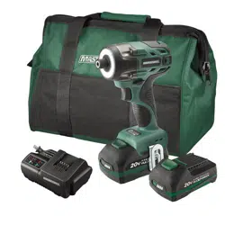
CONTENTS
Cordless impact driver, bit holder, belt clip,bit
and instruction manual.
UNPACKING
1. Carefully remove the tool and any
accessories from the carton. Make sure
that all items listed in the packing list are
included.
2. Inspect the tool carefully to make sure
that no breakage or damage occurred
during shipping.
3. Do not discard the packing material
until you have carefully inspected and
satisfactorily operated the blower.
Page 9
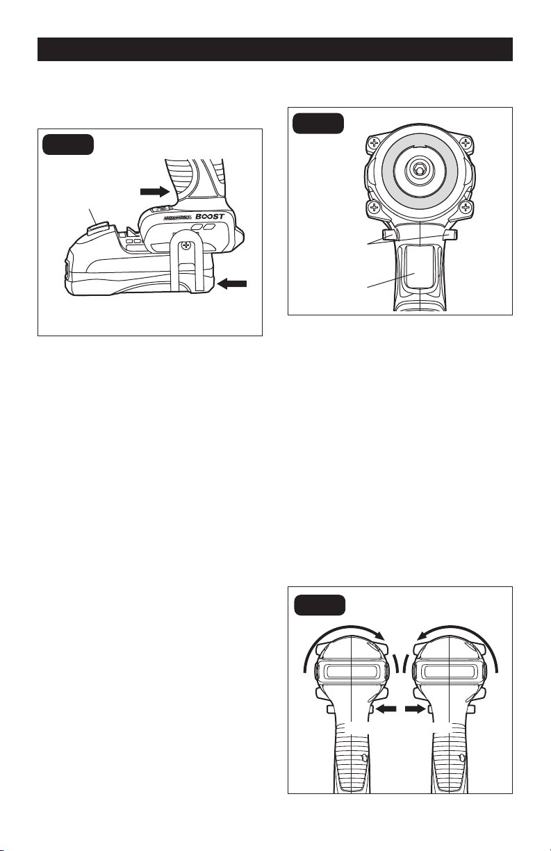
TRIGGER SWITCH (FIG.2)
To turn the impact driver on, depress the
trigger switch.
To turn it off, release the trigger switch.
VARIABLE SPEED
The variable-speed trigger switch delivers
higher speed with increased trigger pressure
and lower speed with decreased trigger
pressure.
DIRECTION-OF-ROTATION SE-
LECTOR (FORWARD/CENTER-
LOCK/REVERSE) (FIG.3)
OPERATION
Direction-of-
rotation Selector
Trigger Switch
FIG. 2
Reverse
Forward
FIG. 3
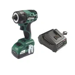
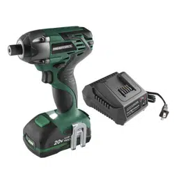
TO ATTACH BATTERY PACK
(FIG. 1)
1. Make sure that the tool is switched off.
2. Align the raised rib on the battery pack
with the grooves on the bottom of the
impact driver, and then slide the battery
pack onto the tool.
NOTICE: Make sure that the latch on the
battery pack snaps into place and the bat-
tery pack is secured to the tool before op-
eration.
TO DETACH BATTERY PACK
(FIG. 1)
1. Make sure that the tool is switched off.
2. Depress the battery-release button
located on the front of the battery pack
to release the battery pack.
3. Pull the battery pack out and remove it
from the tool.
Attach
Battery-release
Button
Detach
FIG. 1
Page 10
The direction of rotation is reversible and is
controlled by a selector located above the
trigger switch. With the impact driver held
in normal operating position: position the
direction-of-rotation selector to the left of
the tool for forward rotation; position the
direction-of-rotation selector to the right
of the tool for reverse rotation. Setting the
switch in the OFF (center-lock) position
helps to reduce the possibility of accidental
starting when not in use.
NOTICE: To prevent gear damage, always
allow the impact driver to come to a com-
plete stop before changing the direction of
rotation.
NOTICE: The impact driver will not run un-
less the direction of the rotation selector is
engaged fully to the left or right.
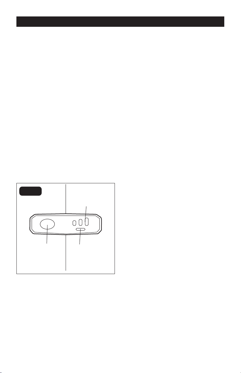
MODE SELECTOR (FIG.4)
NOTICE: The impact driver is designed
with 3-speed and auto-stop functions;
these functions are available only when the
tool is operating in forward rotation.
NOTICE: The mode can only be changed
when the mode-indicator light is on. The
mode-indicator light will be off automati-
cally in about one minute.
1. Attach the battery pack to the impact
driver.
2. Position the direction-of-rotation
selector to the left of the tool for forward
rotation, and press the trigger switch to
turn on the mode-indicator light.
3. Press the mode selector to change the
speed: press once for low, press twice
for medium, and press a third time for
high.
4. To make the Auto-stop function
available, press and hold the mode
selector for three seconds: the auto-
stop indicator will shine. When a bolt/
nut is sufciently tightened, the tool
will automatically stop the impact
and rotation after approximately one
second.
5. To turn off the auto-stop function, press
and hold the mode selector for three
seconds again. The auto-stop indicator
is will turn off.
ELECTRIC BRAKE
The impact driver is equipped with an
electric brake. When the trigger switch
is released, the electric brake engages
automatically to quickly stop the rotation.
OPERATION
L
AUTOSTOP
H
Mode Selector
Mode Indicator
Auto-stop
Indicator
FIG. 4
Page 11
REMOVING THE BELT CLIP
1. Remove the battery from the tool.
2. Use a screwdriver to loosen the screw
that attaches the belt clip to the driver.
3. Remove the screw and the belt clip.
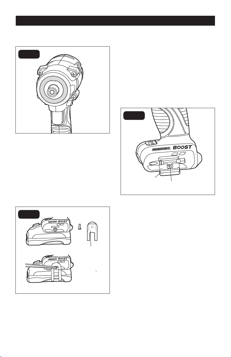
TO INSTALL THE BIT HOLDER
(FIG.7):
1. Remove the battery from the tool.
2. Align the rib of the bit holder with the
hole in the base of the impact driver.
3. Insert the screw (included) and securely
tighten the screw with a screwdriver
(not included). The bit holder can be
positioned on either side of the tool.
To remove the bit holder:
1. Remove the battery from the tool.
2. Use a screwdriver to loosen the screw
that attaches the bit holder to the
impact driver.
3. Remove the screw and the bit holder.
OPERATION
Bit Holder
Screw
FIG. 7
LED WORKLIGHT RING (FIG.5)
The LED worklight rings, located around
the shaft of the impact driver, will illuminate
when the trigger switch is depressed. This
provides additional light on the surface of the
workpiece for operation in lower-light areas.
The light will automatically turn off within 10
seconds after the trigger is released.
INSTALLING THE BELT CLIP
(FIG.6)
1. Remove the battery from the tool.
2. Align the rib of the belt clip with the hole
on the base of the driver.
3. Insert the screw and securely tighten
the screw with a screwdriver.
Belt Clip
FIG. 6
FIG. 5
Page 12
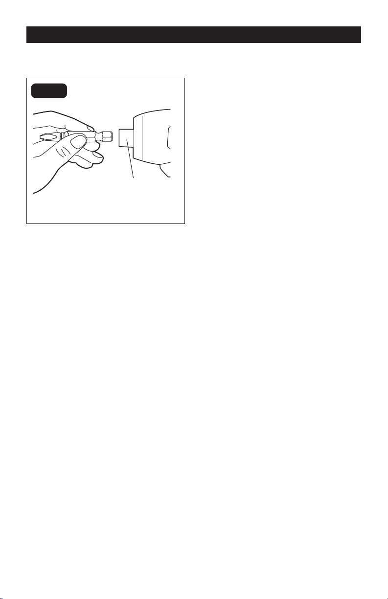
INSTALLING BITS (FIG.8)
1. Lock the trigger switch on the impact
driver by placing the direction-of-
rotation selector in the center position.
2. Insert the bit into the chuck. You will
hear a “click” to indicate that the bit is
securely installed in place.
3. Pull on the bit to check if it installed
securely.
REMOVING BITS
1. Lock the trigger switch on the impact
driver by placing the direction-of-
rotation selector in the center position.
2. Pull the sleeve towards the front of the
tool.
3. The bit should pop out from the chuck
automatically, if not, simply pull out the
bit.
TIGHTENING AND LOOSENING
SCREWS
1. Install the correct bit.
2. Apply just enough pressure to keep the
bit engaged on the screw.
3. Apply minimal pressure to the trigger
switch initially. Increase the speed only
when full control can be maintained.
TIGHTENING AND LOOSENING
NUTS AND BOLTS
Variable speed control must be used with
caution for driving nuts and bolts with
socket set attachments. The best technique
is to start slowly, increasing speed as the
nut or bolt runs down. Set the nut or bolt
snugly by slowing the tool to a stop. If this
procedure is not followed, the tool will have
a tendency to torque or twist in your hands
when the nut or bolt seats.
OPERATION
Sleeve
FIG. 8

Page 13
WARNING:
Always wear safety
goggles or safety glasses with side shields
during power tool operations, or when
blowing dust. If operation is dusty, also
wear a dust mask.
WARNING:
Do not at any time allow
brake fluids, gasoline, petroleum-based
products, penetrating oils, etc. to come in
contact with plastic parts. Chemicals can
damage, weaken or destroy plastic, which
may result in serious personal injury.
MAINTENANCE
The tool may be cleaned most effectively
with compressed dry air. Always wear
safety goggles when cleaning tools with
compressed air.
Avoid using solvents when cleaning plastic
parts. Most plastics are susceptible to
damage from various types of commercial
solvents and may be damaged by their use.
Use a clean cloth to remove dirt, dust, oil,
grease, etc.
BEFORE EACH USE
1. Check for damaged, missing, or worn
parts.
2. Check for loose screws, misalignment
or binding of moving parts, or any other
condition that may affect the operation.
3. If abnormal vibration or noise occurs,
turn the tool off immediately and have
the problem corrected before further
use.
MAINTENANCE

Page 14
TROUBLESHOOTING
PROBLEM CAUSE SOLUTION
The impact driver does
not work.
The battery pack is depleted. Charge the battery pack.
The battery pack or impact
driver is too hot.
Turn off the impact driver and
allow the impact driver and
battery pack to cool.

SAVE YOUR RECEIPTS
THIS WARRANTY IS VOID WITHOUT THEM
1/4” Impact Driver
WARRANTY
90-DAY MONEY BACK GUARANTEE:
This MASTERFORCE® brand power tool carries our 90-DAY Money Back
Guarantee. If you are not completely satised with your MASTERFORCE® brand
power tool for any reason within ninety (90) days from the date of purchase, return
the tool with your original receipt to any MENARDS® retail store, and we will provide
you a refund – no questions asked.
3-YEAR LIMITED WARRANTY:
This MASTERFORCE® brand power tool carries our famous No Hassle 3-Year Limited
Warranty to the original purchaser. If, during normal use, this MASTERFORCE® power
tool breaks or fails due to a defect in material or workmanship within three (3) years
from the date of original purchase, simply bring this tool with the original sales receipt
back to your nearest MENARDS® retail store. At its discretion, MASTERFORCE®
agrees to have the tool or any defective part(s) repaired or replaced with the same or
similar MASTERFORCE® product or part free of charge, within the stated warranty
period, when returned by the original purchaser with original sales receipt. Not
withstanding the foregoing, this limited warranty does not cover any damage that
has resulted from abuse or misuse of the Merchandise. This warranty: (1) excludes
expendable parts including but not limited to blades, brushes, belts, bits, light bulbs,
and/or batteries; (2) shall be void if this tool is used for commercial and/or rental
purposes; and (3) does not cover any losses, injuries to persons/property or costs. This
warranty does give you specic legal rights and you may have other rights, which vary
from state to state. Be careful, tools are dangerous if improperly used or maintained.
Seller’s employees are not qualied to advise you on the use of this Merchandise.
Any oral representation(s) made will not be binding on seller or its employees. The
rights under this limited warranty are to the original purchaser of the Merchandise
and may not be transferred to any subsequent owner. This limited warranty is in lieu
of all warranties, expressed or implied including warranties or merchantability and
tness for a particular purpose. Seller shall not be liable for any special, incidental, or
consequential damages. The sole exclusive remedy against the seller will be for the
replacement of any defects as provided herein, as long as the seller is willing or able
to replace this product or is willing to refund the purchase price as provided above.
For insurance purposes, seller is not allowed to demonstrate any of these power tools
for you.
For questions / comments, technical assistance or repair parts –
Please call toll free: 1-866-917-4374 (M-F 8:30am – 5:00pm EST).

11/2020
© 2020 Menard, Inc., Eau Claire, WI 54703