CTHK 630
CTHK 631
CTHK 632
CTHK 633
CTHK 634
CTHK 635
CTHK 636
Montage- und
Gebrauchsanweisung
DeutschEnglishFrançais
Instructions d’installation
et d’utilisation
Installation and
Operating Instructions
Bestell-Nr. / Order no. / No de commande : E.G.O. / CTHK FD 9007


www.dimplex.de D-1
Deutsch
Inhaltsverzeichnis
1 Funktion ........................................................................................................................................ D-2
2 Energiesparen .............................................................................................................................. D-2
3 Bedienung und Temperatureinstellung ..................................................................................... D-2
4 Betriebsvoraussetzungen ........................................................................................................... D-2
5 Montage-, Einbau- und Sicherheitshinweise ............................................................................. D-3
5.1 Allgemeine Einbau- und Sicherheitshinweise.........................................................................................D-3
5.2 Aufbauskizzen ........................................................................................................................................D-4
5.3 Montage des Einschraubheizkörpers .....................................................................................................D-4
5.4 Einbau in emaillierte Trinkwasserspeicher .............................................................................................D-5
5.5 Hinweise zum Korrosionsschutz.............................................................................................................D-5
5.6 Elektrischer Anschluß .............................................................................................................................D-5
5.7 Erste Inbetriebnahme .............................................................................................................................D-6
6 Kontrolle, Wartung, Pflege .......................................................................................................... D-6
7 Funktionsstörungen..................................................................................................................... D-6
8 Technische Daten......................................................................................................................... D-7

D-2
Deutsch
1
1 Funktion
ACHTUNG!
Dieses Gerät ist nicht dafür bestimmt, durch Personen (einschließlich
Kinder) mit eingeschränkten physischen, sensorischen oder geistigen
Fähigkeiten oder mangels Erfahrung und/oder mangels Wissen benutzt
zu werden, es sei denn, sie werden durch eine für ihre Sicherheit
zuständige Person beaufsichtigt oder erhielten von ihr Anweisungen, wie
das Gerät zu benutzen ist. Kinder sollten beaufsichtigt werden, um
sicherzustellen, dass sie nicht mit dem Gerät spielen.
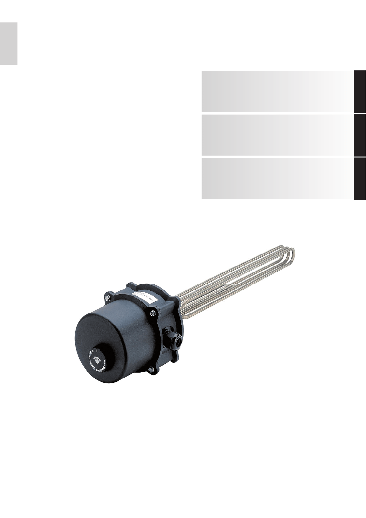
Die Einschraubheizkörper CTHK 630 bis CTHK 636 sind für den
Einbau in Heizungspufferspeicher sowie in Trinkwarmwasser-
Speicher (im Durchflussprinzip PWD) vorgesehen. Sie sind als
Haupt- u. Zusatzheizung für (elektrisch) zu beheizende Speicher
wartungsfrei. Bei stark kalkhaltigem Wasser ist es sinnvoll, in ge-
wissen Zeitabständen die Heizkörper von Kesselstein zu be-
freien.
Der Nutzer kann die gewünschte maximale Temperatur am
Drehregler vorwählen. Die Heizung wird, während der (vom zu-
ständigen EVU festgelegten) Aufheizzeit, durch den Temperatur-
regler (oder Regler des Wärmeerzeugers) selbsttätig ein - und
nach Erreichen der gewünschten Speicherwassertemperatur
wieder abgeschaltet. Sinkt die Wassertemperatur, z.B. durch
eine Heizungsanforderung oder natürliche Abkühlung, so schal-
tet sich der Einschraubheizkörper solange wieder ein, bis die
vorgewählte Speicherwassertemperatur erreicht ist.
2 Energiesparen
Je niedriger die Speicherwassertemperatur gewählt wird umso
wirtschaftlicher erweist sich die Wärmeerzeugung. Deshalb ist
es empfehlenswert die stufenlos einstellbare Temperatur nur so
hoch zu wählen, wie sie für den tatsächlichen Warm- oder Spei-
cherwasserbedarf benötigt wird. Ein positiver Nebeneffekt ist,
dass sich hierdurch nicht nur Elektroenergie einsparen lässt,
sondern auch Kalkablagerungen im Speicher weitestgehend ver-
mieden werden! Zudem kann in Verbindung mit dem Wärme-
pumpenmanager (WPM) durch das Einstellen der Grenztempe-
ratur (Bivalenzpunkt) ein unnötiges Zuschalten des
Einschraubheizkörpers vermieden werden.
3 Bedienung und
Temperatureinstellung
Die Wassertemperatur im Speicher kann entsprechend ihrem
Wasserbedarf mit dem Temperaturwähler stufenlos oder anhand
der markierten Hauptheizstufen eingestellt werden. Somit ist ein
bedarfsgerechter und energieeffizenter Betrieb des Einschraub-
heizkörpers möglich!
HINWEIS
Bei Ansteuerung des Einschraubheizkörpers über den
Wärmepumpenmanager muss die elektrische Zusatzheizung mit Hilfe
des Drehreglers auf die max. zulässige Vorlauftemperatur der
Wärmepumpe eingestellt werden!!!
Als Einstellhilfe weist der Knebel des Temperaturreglers an der
Elektroheizung vier markierte Hauptstufen auf:
Stellung:
Frostschutz für den Speicher
Stellung:
Y
ca. 40°C, handwarmes Speicherwasser (empfohlen bei Wohn-
raumbeheizung mit Fussbodenheizung).
Stellung:
••
ca. 60°C, mäßig heißes Speicherwasser. Um zu hohe Wasser-
temperaturen im Speicher auszuschließen ist diese Stellung zu
empfehlen (empfohlen bei Wohnraumbeheizung mit Radiato-
ren).
Bei dieser Einstellung arbeitet das Gerät besonders wirtschaft-
lich. Die Wärmeverluste sind gering, und die Kesselsteinbildung
wird weitgehend vermieden.
Niedriger Bereitschaftsenergieverbrauch!!!
Stellung:
•••
ca. 80°C, heißes Speicherwasser (nur bei älteren Radiatoren
mit hohen Vorlauftemperaturen).
ACHTUNG!
Die Einstellung des Reglerknebels auf linken Anschlag entspricht keiner
Nullstellung bzw. hat keine Abschaltung der Geräteheizung zur Folge.
Beim Betrieb mit Tagstrom wird empfohlen den Temperaturreg-
ler nicht höher als auf Stellung oo (ca. 60°C) einzustellen.
4 Betriebsvoraus-
setzungen
Die Einschraubheizkörper sind ausschließlich gemäß den am
Leistungsschild genannten Bedingungen (Betriebsdruck, Auf-
heizzeit, Anschluss-Spannung etc.) einsetzbar. Die elektrische
Verbindung ist nach dem an der Innenseite der Schutzkappe auf-
geklebten Anschlussplan herzustellen.
Neben den gesetzlich anerkannten nationalen Vorschriften (VDE
bzw. DIN EN usw.) sind auch die Anschlussbedingungen der ört-
lichen Elektrizitäts- und Wasserwerke einzuhalten sowie den An-
weisungen der Montage- und Bedienungsanleitung Folge zu
leisten.
Alle Einschraubheizkörper sind für druckfesten Betrieb und der
Aufheizung von Heizungswasser bis zu einem max. Betriebs-
druck von 10 bar geeignet.
Bei stark kalkhaltigem Wasser wird die Vorschaltung eines han-
delsüblichen Entkalkungsgerätes empfohlen.
Die Einschraubheizkörper sind geeignet für den Einbau in Stand-
speicher jeglicher Art sowie Doppelmantelgeräten. Durch die be-
sondere Konzeption können die Geräte aber auch in Fremdfabri-
kate mit emaillierten, kunststoffbeschichteten oder
feuerverzinkten Kesseln eingebaut werden. Eine Kombination
mit CrNi-Kesseln (NIRO) ist problematisch und daher nicht zu
empfehlen. (Kap. 5.4 auf S. 3).
D-3
Deutsch
5.1
Normen
Die Einschraubheizkörper CTHK sind VDE-geprüft und entspre-
chen den Bestimmungen nach:
DIN EN 60335-1
DIN VDE 0700-253
DIN EN 60529, Schutzklasse IP54
DIN 1988 technische Regeln für
Trinkwasser-Installation (TRWI)
EU-Richtlinie 2006/95/EG (Niederspannungsrichtlinie)
EU-Richtlinie 1935/2004/EG (Lebensmittelkontakt)
EU-Richtlinie 97/23/EG (Druckbehälterrichtlinie)
Das Kunststoffmaterial des Anschlussgehäuses entspricht den
Anforderungen gemäß § 5 Abs. 1 des Lebensmittel- und Be-
darfsgegenstandsgesetzes sowie den Empfehlungen des Bun-
desinstituts für Gesundheitlichen Verbraucherschutz (KTW-Zu-
lassung).
5 Montage-, Einbau- und
Sicherheitshinweise
5.1 Allgemeine Einbau- und
Sicherheitshinweise
ACHTUNG!
Montage des Heizeinsatzes und die erste Inbetriebnahme dürfen nur von
fachkundigem Personal durchgeführt werden! Bei unsachgemäßer
Montage erlischt jeglicher Garantieanspruch!
Der Einschraubheizkörper CTHK muss von einem Fachmann in-
stalliert werden, der für die Einhaltung der bestehenden Normen
und Installationsvorschriften verantwortlich ist.
Bei der Installation des Einschraubheizkörpers sind folgende
Vorschriften zu beachten:
Die Vorschriften des VDE und der örtlichen EVU
Die Heizungsanlagenverordnung (HeizAnl.V)
Bei Verwendung in Druckbehältern: das AD-Merkblatt A3,
Abschnitt 3.28
Die Normen der Reihe DIN 1988
Bei geschlossenen Wassererwärmern ist die Anordnung der
verwendeten Armaturen und Sicherheitseinrichtungen un-
bedingt zu beachten (gem. länderspezifischen Normen).
Im Betrieb müssen Elektro-Heizkörper und Fühlerrohr komplett
von Wasser umgeben sein. Die thermisch bedingte Wasserströ-
mung darf nicht behindert werden.
Der Einschraubheizkörper ist mit einem Sicherheitstemperatur-
begrenzer ausgestattet, der bei einer Wassertemperatur von
max. 95°C die weitere Beheizung des Gerätes abschaltet. Ent-
sprechend der Norm DIN EN 60335-2-21 darf die max. Wasser-
temperatur um + 20°C höher liegen (
⇒115°C) und hat damit
auch Einfluss auf alle weiteren "Bauteile und Einbauten" im Wär-
meverteilsystem und Erzeugungskreis!
HINWEIS
Bei der Verwendung einer Druckentlastungseinrichtung ist
sicherzustellen, dass Wasser aus dem Abflussrohr der
Druckentlastungseinrichtung tropfen kann und dieses Rohr zur
Atmosphäre hin offen gelassen werden muss; ·die Druckentlastungs-
einrichtung regelmäßig betrieben werden muss, um Kalkablagerungen zu
entfernen und um sicher zu sein, sie nicht blockiert ist; eine an die
Druckentlastungseinrichtung angeschlossene Abflussleitung mit einer
stetigen Abwärtsneigung in einer frostfreien Umgebung zu installieren
ist.
Es ist darauf zu achten, dass alle Anschlusskomponenten (An-
schlussrohre, Sicherheitsventil-Kombinationen etc.) bei einer
eventuellen Fehlfunktion des Temperaturreglers der max. mögli-
chen Reglertemperatur (gemäß Norm) Stand halten und Folge-
schäden vermieden werden.
Bei stark kalkhaltigem Wasser beeinträchtigt Kesselsteinbildung
die Funktion. Hier sind entsprechende Vorkehrungen zu treffen,
wie z. B. Temperaturabsenkung, Einbau einer Enthärtungsan-
lage oder das regelmäßige Entfernen des Kesselsteines.
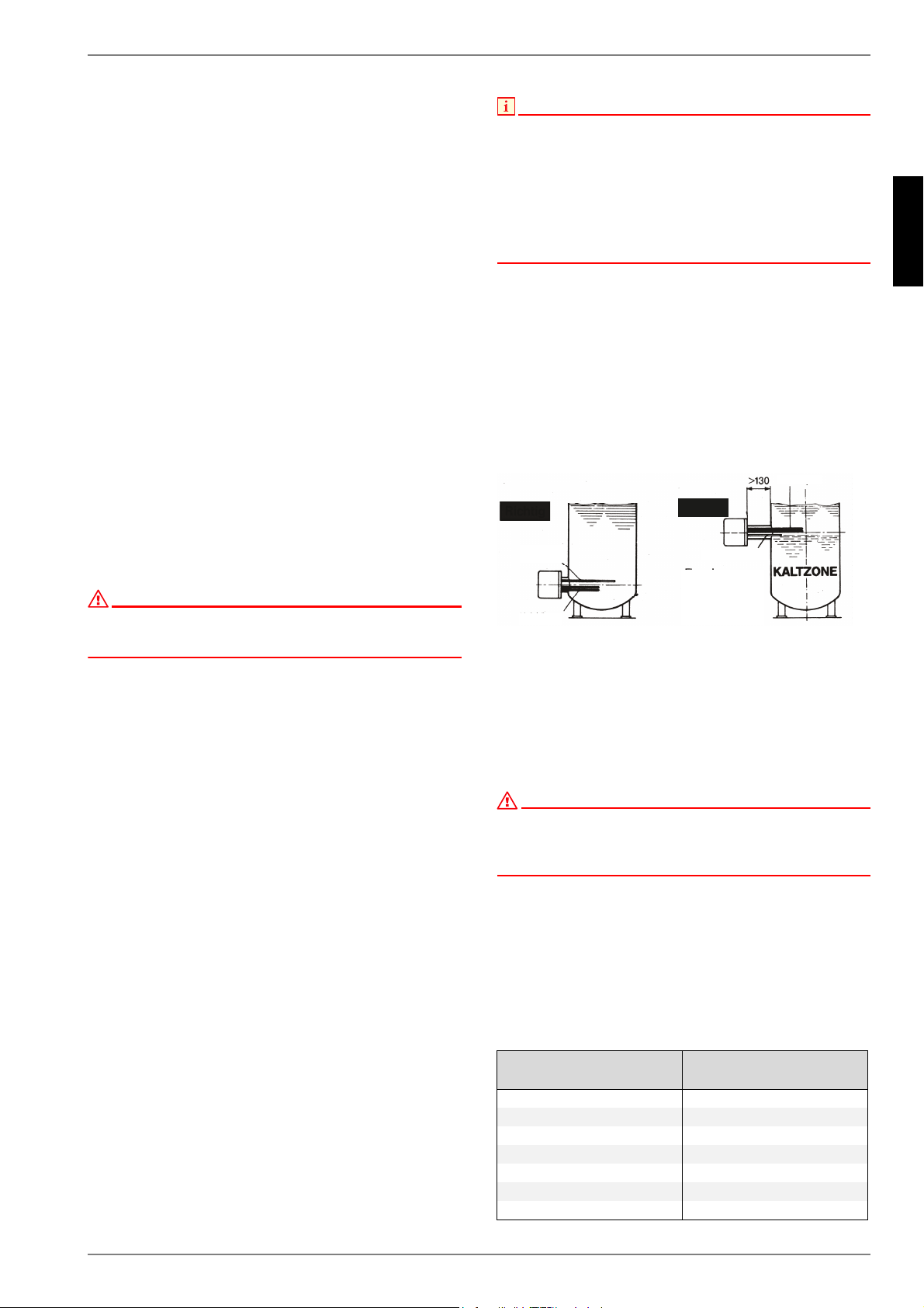
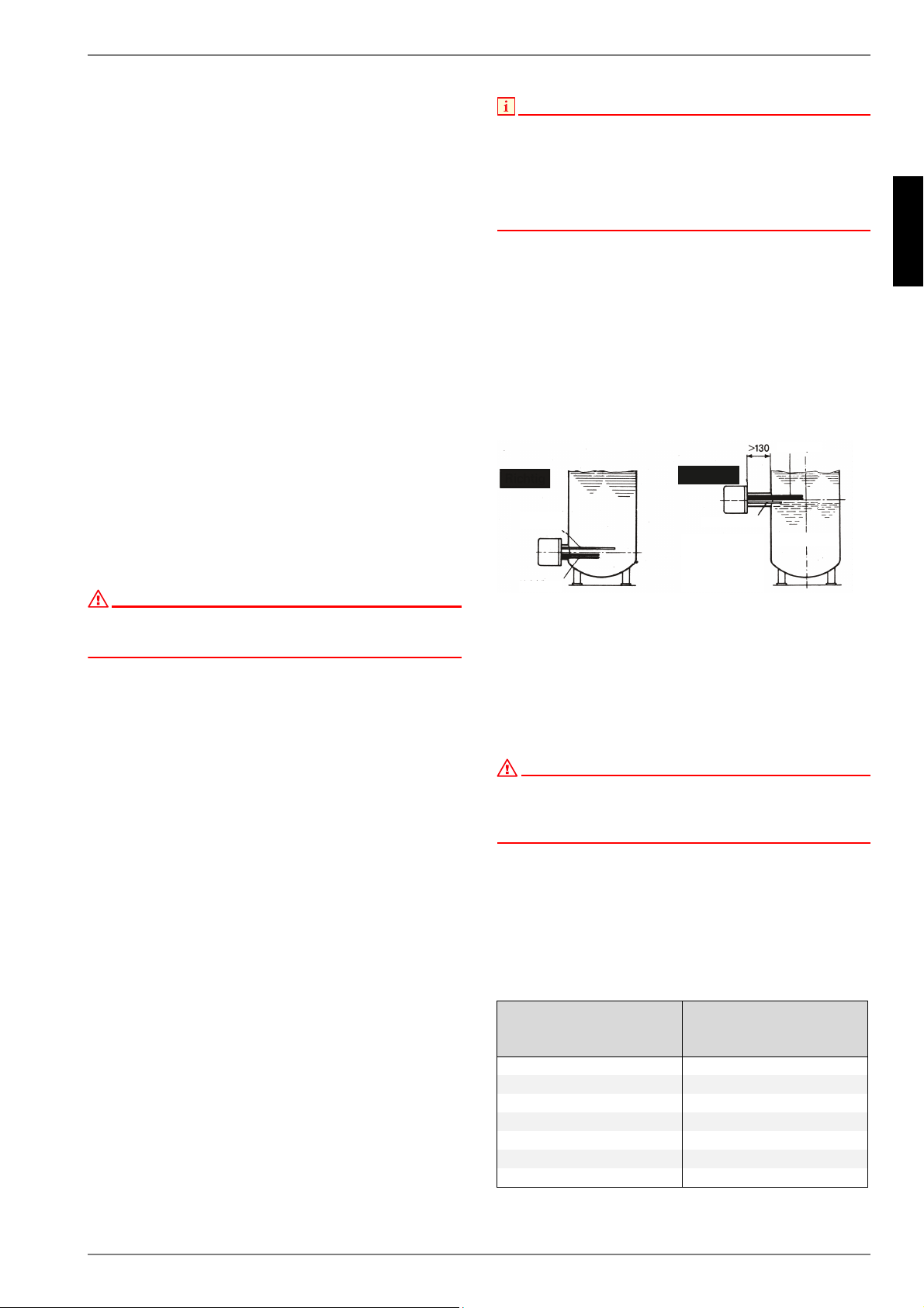
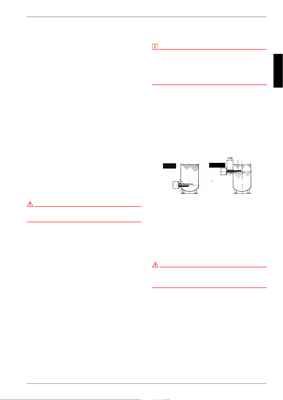
Einbaulage:
Die Anschlussmuffe R 1 ½" des Speichers darf nicht länger als
max. 130 mm sein, damit Temperaturfühler und Heizkörper noch
ausreichend in den Kessel ragen.
Der Einschraubheizkörper ist im Kessel möglichst weit unten ein-
zubauen, um den ganzen Kesselinhalt gleichmäßig zu erwär-
men.
Vor der Anschlussmuffe ist ein Mindestabstand (Einbaulänge +
100 mm) für Montage etc. einzuhalten.
ACHTUNG!
Bei der Montage auf die richtige Einbaulage des Tauchrohres
(Temperaturfühler) achten. Grundsätzlich sollte sich das Tauchrohr über
(1-phasig) bzw. über und zwischen (3-phasig) dem/den Heizelement(en)
befinden!
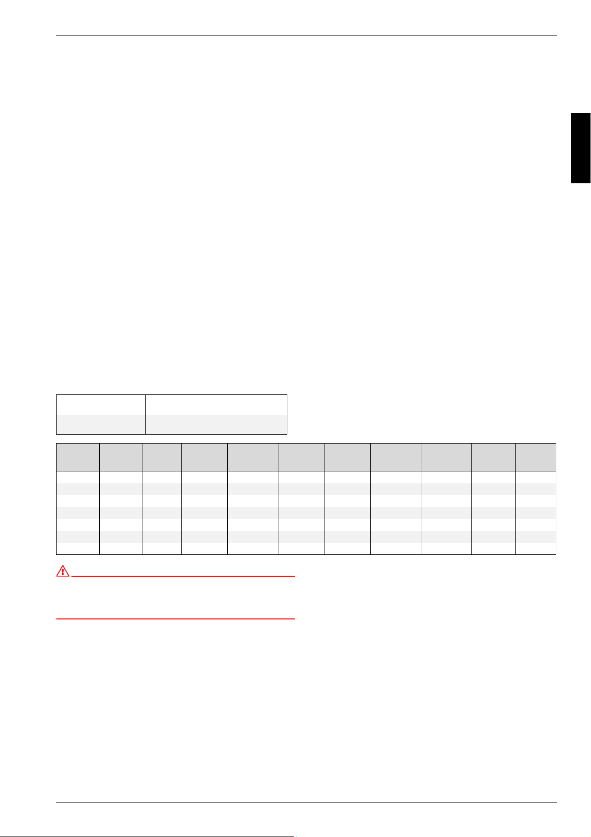
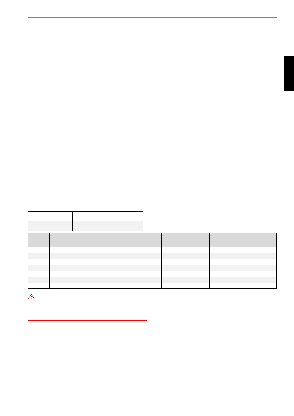
Empfohlene Flüssigkeitsmengen
In Relation zur Leistungsaufnahme werden die angegebenen
(siehe Tabelle unten) zu erwärmenden Flüssigkeitsmengen im
Sinne der VDE 0700 Teil 73 § 7.12.1 empfohlen.
Die Angaben der Flüssigkeitsmengen verstehen sich als Min-
destmengen. Abweichungen je nach Applikation sind möglich.
Rohrheizkörper müssen in jeder Applikation von einer ausrei-
chenden Menge Flüssigkeit bedeckt sein.
Nennaufnahme
(W)
Flüssigkeitsmenge (ca.)
(Liter)
2000 5
3000 8
4500 12
6000 16
7500 20
9000 24
12000 32
5LFKWLJ
)DOVFK
7HPSHUDWXUUHJOHU
+HL]N|USHU
7HPSHUDWXU
UHJOHU
+HL]N|USHU
)ODQVFK]DUJH]XODQJ
XQG]XKRFK
HLQJHVFKZHLW
7HPSHUDWXUUHJOHU
XQWHU+HL]N|USHU
D-4
Deutsch
5.2
5.2 Aufbauskizzen 5.3 Montage des
Einschraubheizkörpers
Neben den gültigen Gesetzes-Vorschriften sind den Anschluss-
bedingungen der örtlichen Elektrizitäts- und Wasserwerke Folge
zu leisten.
1) Calogen-Heizkörper komplett, wenn möglich bis zum An-
schlag in das Gewinde der Speicher-Anschlussmuffe ein-
schrauben, anschließend auf festen Sitz überprüfen und ge-
gebenenfalls nachziehen. Ein Eindichten mit Hanf oder
Teflonband ist möglich.
2) Schutzkappe entfernen.
3) Elektrischen Anschluss laut Schaltbild herstellen, (siehe
Punkt 5.6). Auf Zugentlastung des Elektrokabels achten.
ACHTUNG!
Schutzleiteranschluss nicht vergessen!
4) Schutzkappe aufsetzen und festschrauben, beigepackten
Reglerknebel aufstecken.
ACHTUNG!
Vor Inbetriebnahme muss der Speicher mit Wasser gefüllt sein.
5) Nach dem Befüllen des Speichers die Anschlussverschrau-
bung des Heizkörpers auf evtl. Leckagen kontrollieren, ggf.
Einschraubheizkörper nachziehen.
D-5
Deutsch
5.6
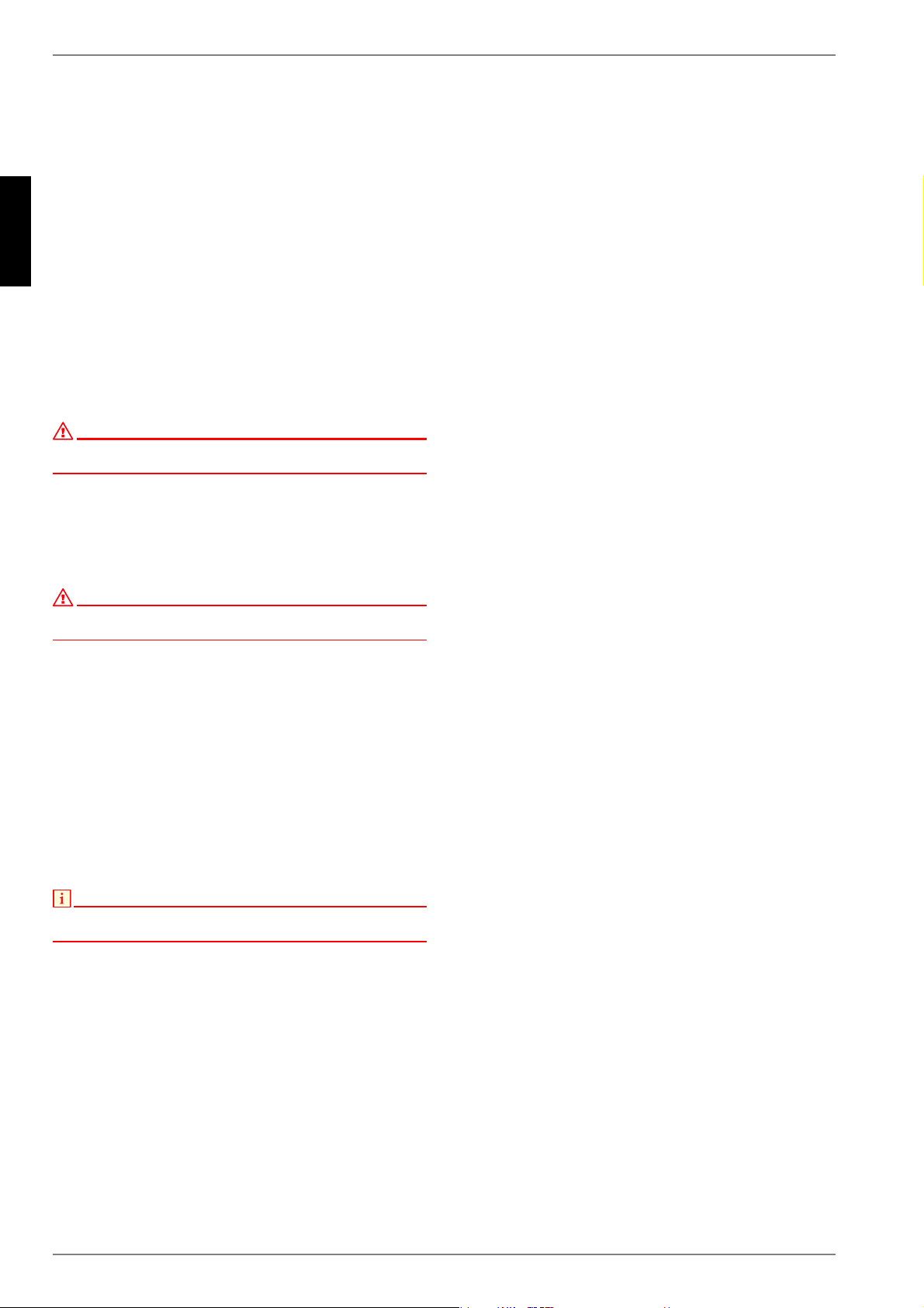
5.4 Einbau in emaillierte
Trinkwasserspeicher
Die Montage-, Anschluss- und Bedienungsanleitung des Hei-
zungsspeichers sind unbedingt einzuhalten, ebenso die techni-
schen Regeln für Trinkwasser-Installationen (TRWI) nach DIN
1988 bei Trink-Warmwasserspeichern.
Druckfester Anschluss
Bei Verwendung von ungeeigneten oder funktionslosen Spei-
cheranschlußarmaturen erlischt jeglicher Garantieanspruch.
Dies gilt auch bei der Überschreitung des angegebenen Be-
triebsdruckes.
Der Wasseranschluss darf nur über ein baumustergeprüftes
Membransicherheitsventil oder eine Membransicherheitsventil-
kombination (Anschlussarmatur für druckfeste Speicher) erfol-
gen!
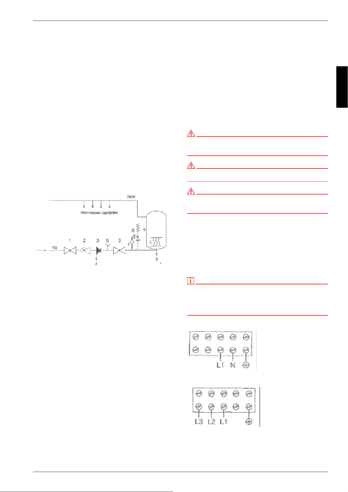
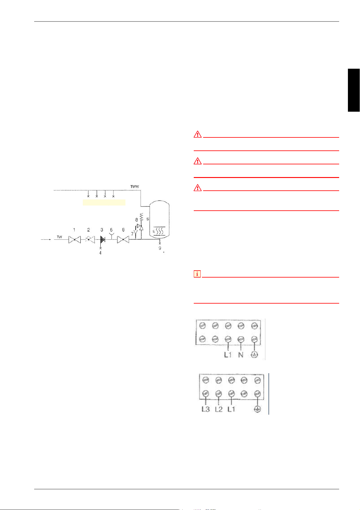
Eine Sicherheitsventilkombination besteht aus Absperr-, Prüf-,
Rücklauf-, Entleerungs- und Sicherheitsventil mit Dehnwasser-
ablauf. Dieses Bauteil wird zwischen Kaltwasserzuleitung und
Kaltwasserzulauf des Speichers in gezeichneter Reihenfolge
eingebaut.
1) Absperrventil
2) Druckminderer
3) Rückflussverhinderer
4) Prüfventil
5) Anschluss für Messgeräte
6) Absperrventil
7) Ablauf- bzw. Auffangtrichter
8) Sicherheitsventil
9) Entleerungsventil
E Einschraubheizkörper (Elektroheizelement)
S Geschlossener Speicher (Wassererwärmer)
TW Trinkwasserleitung (Kaltwasser)
TWW Trinkwasserleitung Warmwasser
Die verwendeten Sicherheitsventile müssen so eingestellt wer-
den, dass der Druck im Behälter nicht mehr als 1 bar über den
Nennwert ansteigt.
Bei geschlossenen Wassererwärmern ist die Anordnung der Ar-
maturen und Sicherheitseinrichtungen zu beachten.Bei offenen
Wasserbehältern müssen die Wasserauslaufsysteme so ausge-
legt sein, dass der Druck im Behälter den Nenndruck nicht über-
steigt.
5.5 Hinweise zum
Korrosionsschutz
Bei emaillierten Speichern ist kesselseitig nach den Angaben
des Herstellers ein entsprechender Anodenschutz vorzusehen.
Die Schutzanoden (Opferanoden) des Behälters sollten erneuert
werden, wenn mehr als 3/4 des Materials abgebaut ist (erste
Kontrolle nach ca. 2-jähriger Betriebszeit, bei kalkhaltigem Was-
ser regelmäßig, spätestens aber nach ca. 1 Jahr).
5.6 Elektrischer Anschluß
ACHTUNG!
Die Montage des Heizeinsatzes und die erste Inbetriebnahme dürfen aus
Garantiegründen nur durch autorisiertes und fachkundiges Personal
erfolgen.
ACHTUNG!
Der elektrische Anschluss ist grundsätzlich nach dem typenbezogenen
Schaltbild (Klemmenplan im Gehäusedeckel) vorzunehmen.
ACHTUNG!
Auf die richtige Anschluss-Spannung ist zu achten!
Alle berührbaren Metallteile des Behälters sind in die Schutzmaßnahme
einzubeziehen.
In der elektrischen Zuleitung ist ein Trennschalter (1- oder 3-po-
lig) mit einer 3 mm Kontaktöffnungsweite vorzusehen. Als Trenn-
schaltvorrichtung sind auch Sicherungsautomaten (träge) zuläs-
sig.
Das Anschlusskabel muß durch die mitgelieferte Verschraubung
in den Einschraubheizkörper eingeführt und mittels einer Zugent-
lastungsvorrichtung gegen Herausziehen und Verdrehen gesi-
chert werden.
HINWEIS
Für den elektrischen Berührungsschutz bei emaillierten Warmwasser-
Speichern ist es notwendig, dass die Heizeinsätze nur in Wasserbereitern
eingesetzt werden bei welchen der Wasserzu- und –ablauf aus Metall
bestehen und an die Schutzleiterklemme angeschlossen sind
(Potentialausgleich).
1~230 V: Type CTHK 630 und CTHK 631
3~400 V: Type CTHK 632 bis CTHK 636

D-6
Deutsch
5.7
Ausführung mit Schützsteuerung
Bei der Installation sind VDE-geprüfte Schaltschütze zu verwen-
den, die bauseits z. B. in einem Schaltschrank oder in einer Elek-
troverteilung installiert werden. Für den Sicherheitstemperatur-
begrenzer und den Temperaturregler sind getrennte
Schaltschütze zu verwenden. Die Schütze müssen mit einer Auf-
schrift versehen sein, die ihre Sicherheitsfunktion für den Wasse-
rerwärmer (Flanschheizung) kenntlich macht. (TR und STB).
Die Leistungsangaben für die Auswahl der Schütze sind aus der
Tabelle 8 (Abschn. Technische Daten) unter den Spalten
"Schaltgruppe" zu entnehmen. Das STB-Schütz muss für die
Gesamtleistung der Schaltgruppen ausgelegt sein. Nach erfolg-
ter Installation muss die einwandfreie Funktion der Schütze ge-
prüft werden.
5.7 Erste Inbetriebnahme
ACHTUNG!
Vor der elektrischen Inbetriebnahme muß der Speicher mit Wasser gefüllt
sein.
Während des Aufheizvorganges muss das im Innenkessel ent-
stehende Wasser bei druckfestem Anschluss aus dem Sicher-
heitsventil, bei drucklosem Anschluss aus der Überlaufmischbat-
terie tropfen oder in ein angeschlossenes Ausdehnungsgefäß
fließen.
ACHTUNG!
Warmwasserablaufrohr sowie Teile der Sicherheitsarmatur können heiß
werden.
6 Kontrolle, Wartung,
Pflege
Bei stark kalkhaltigem Wasser ist die Entfernung
des sich im Speicherinneren bildenden Kesselsteines sowie
des frei abgelagerten Kalkes
nach ein bis zwei Betriebsjahren durch einen Fachmann erfor-
derlich.
HINWEIS
Der Innenbehälter eines emaillierten Warmwasserspeichers darf nicht mit
Kesselsteinlösemittel in Berührung kommen. Nicht mit einer
Entkalkungspumpe arbeiten.
Für die Reinigung des Gerätes keine scheuernden Putzmittel
und keine Farbverdünnungen (wie Nitro, Trichlor usw.) verwen-
den. Abschließend das Gerät gründlich ausspülen und den Auf-
heizvorgang beobachten.
7 Funktionsstörungen
Wird das Speicherwasser nicht aufgeheizt, prüfen Sie bitte, ob
im Verteiler der Leitungsschutzschalter / Sicherungsautomat
oder die Schmelzsicherung ausgelöst hat. Kontrollieren Sie auch
die Einstellung des Temperaturreglers.
In allen anderen Fällen versuchen Sie nicht, die Störung selbst
zu beheben. Wenden Sie sich bitte entweder an einen fachkun-
digen Installateur oder an unseren Kundendienst.
D-7
Deutsch
8
8 Technische Daten
Alle verwendeten Werkstoffe bieten gute wärmetechnische,
elektrische und mechanische Eigenschaften und größtmöglichen
Schutz vor Korrosion.
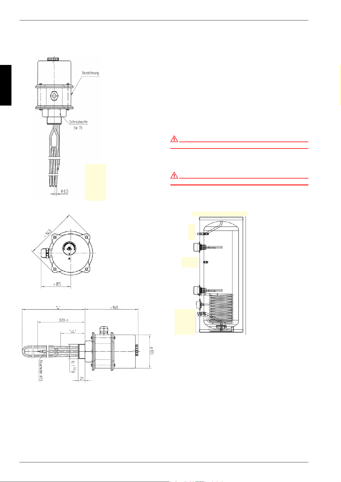
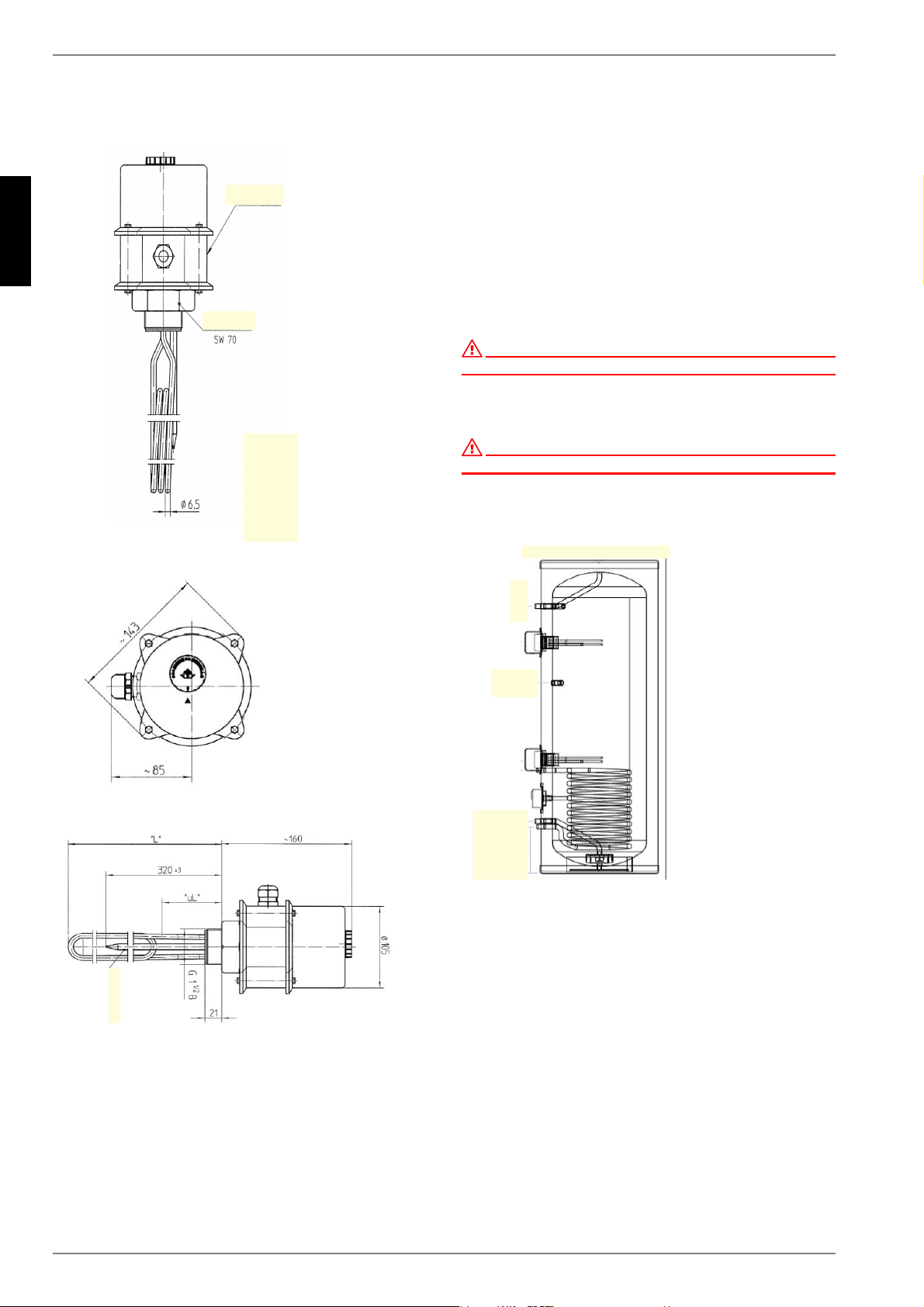
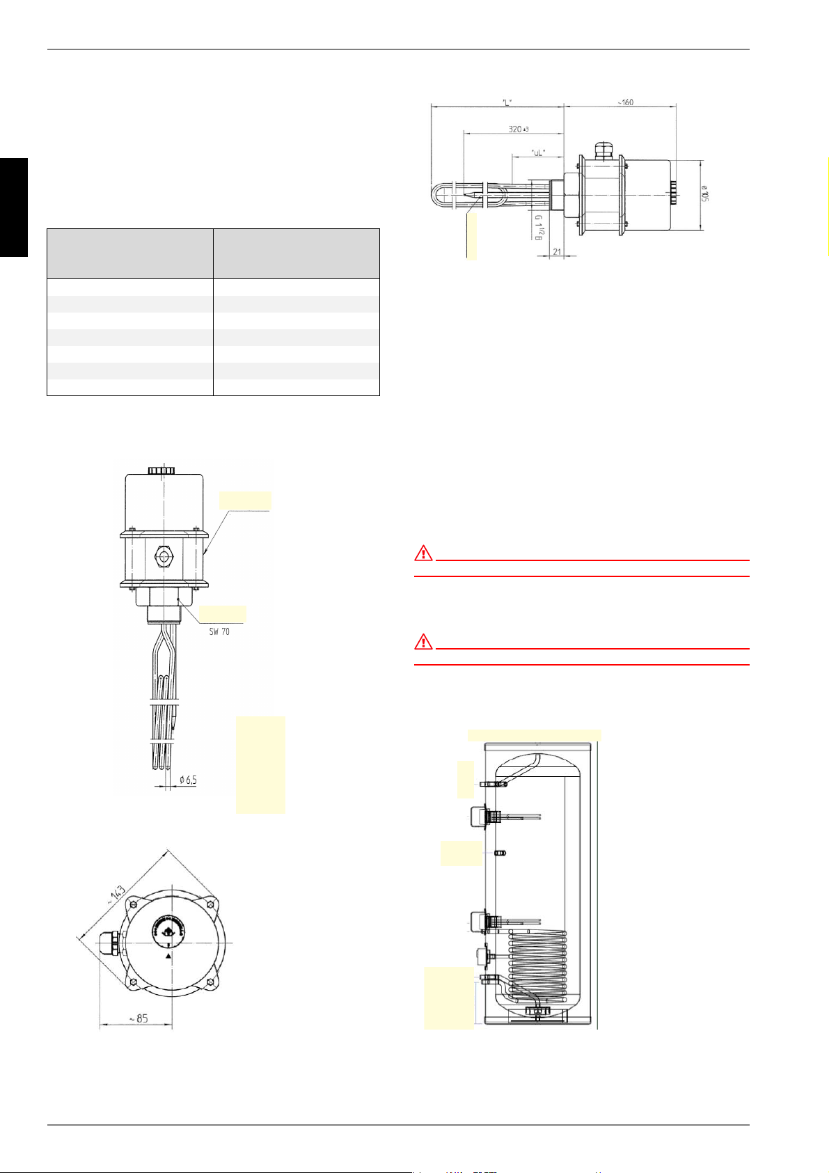
Die Einschraubheizkörper bestehen aus einem Edelstahlmantel
(Ø 6,5 mm, Werkstoff 2.4858 / INCOLOY 825) mit einer hochver-
dichteten Isoliermasse, in die eine Heizwendel eingebettet ist.
Der Schraubkopf mit Einschraubgewinde G 1 ½“ besteht aus
Edelstahl (Werkstoff 1.4301 / AISI 304).
Das Anschlussgehäuse lässt sich nach der Fixierung des Ein-
schraubgewindes in vier verschiedenen, jeweils um 90° versetz-
ten Positionen montieren.
Höhe der Schutzkappe: 120 mm Einstellbereich des Tempera-
turwählers:
Durchmesser der Schutzkappe 120 mm (ohne Zugentlastung
und Verschraubung)
Einschraubheizkörper
einstellbar von 30°C bis ca. 80°C, sowie Frostschutzstel-
lung. Die entsprechende Flanschdichtung ist beigepackt.
Temperaturregeler (TR) mit Sicherheitstemperaturbegren-
zer (STB) gem. DIN EN 60335-2-21
Frostschutzstufe 11 °C +/- 7K
Schutzart IP 54
Der Einschraubheizkörper ist bis zu einem statischen Druck von
10 bar geprüft. Der maximale Betriebsdruck darf 10 bar nicht
überschreiten.
ACHTUNG!
Beim elektrischen Anschluss:
Der Einschraubheizkörper CTHK 630 - 636 werden mittels Schütz an den
Wärmepumpenmanager angeschlossen. Beachten Sie hierbei auch den
Klemmenplan des Wärmepumpenmanagers.
CTHK 630 und CTHK 631:
Einphasige Ausführung
für Direktanschluss 1 ~ 230 Volt
CTHK 632 - CTHK 636:
Drehstrom-Ausführung
für Direktanschluss 3 ~ 400 Volt
Type
Nenn-
leistung
in KW
Nenn-
spannung
in V
Heizkörper-
anzahl
Schaltgruppe 1
in KW
Eintauchtief
in mm
Unbeheizte
Länge
in mm
Montage-
möglichkeit
waagrecht
Anschluss-
gewinde
DVGW
und KTW-
Zulassung
Prüfzeichen
VDE
CTHK 630 4,5 ~230 1 4,5 400 95 x R 1 1/2“ x x
CTHK 631 2,0 ~230 1 2,0 250 95 x R 1 1/2“ x x
CTHK 632 2,9 3~400 3 2,9 250 95 x R 1 1/2“ x x
CTHK 633 4,5 3~400 3 4,5 350 110 x R 1 1/2“ x x
CTHK 634 6,0 3~400 3 6,0 450 110 x R 1 1/2“ x x
CTHK 635 7,5 3~400 3 7,5 550 110 x R 1 1/2“ x x
CTHK 636 9,0 3~400 3 9,0 650 110 x R 1 1/2“ x x

D-8
Deutsch
8

www.dimplex.de E-1
English
Table of contents
1 Function .........................................................................................................................................E-2
2 Energy saving................................................................................................................................E-2
3 Operation and temperature setting .............................................................................................E-2
4 Operational requirements.............................................................................................................E-2
5 Assembly, installation and safety instructions..........................................................................E-3
5.1 General installation and safety instructions ............................................................................................ E-3
5.2 Layout diagrams .....................................................................................................................................E-4
5.3 Screw-in heater mounting set .................................................................................................................E-4
5.4 Installation in enamelled drinking water cylinders...................................................................................E-5
5.5 Notes on corrosion protection.................................................................................................................E-5
5.6 Electrical connection...............................................................................................................................E-5
5.7 Initial start-up ..........................................................................................................................................E-6
6 Inspection, maintenance and service..........................................................................................E-6
7 Malfunctions ..................................................................................................................................E-6
8 Technical data ...............................................................................................................................E-7

E-2
English
1
1 Function
ATTENTION!
This device is not intended for use by persons, including children, with
restricted physical, sensory or mental abilities or who lack the necessary
knowledge or experience, except under the supervision of a person
responsible for their safety or unless they have been instructed by this
person as to how the device is to be used. Children must be supervised
to ensure that they do not play with the device.
The CTHK 630 to CTHK 636 screw-in heaters can be installed in
heating system buffer tanks and domestic hot water cylinders
(PWD according to the flow principle). No maintenance is
necessary when electronic screw-in heaters are used as main
heaters or for supplementary heating for (electrically) heated
cylinders. In the case of very hard water, periodic cleaning of the
heating elements to remove limescale is recommended.
The user can pre-select the desired maximum temperature on
the rotary controller. During the heat-up time (determined by the
utility company responsible), the heating is automatically
switched on and - after reaching the desired temperature in the
water cylinder - switched off again by the temperature controller
(or the controller of the heat generator). If the water temperature
drops, e.g. due to a heating request or natural cooling, the screw-
in heater will be switched on automatically until the pre-selected
water cylinder temperature is reached.
2 Energy saving
The lower the cylinder water temperature selected, the more
economical the heat generation. The infinitely adjustable
temperature should therefore only be set as high as is needed for
the actual hot water or cylinder water requirement. As a positive
side effect, this not only saves electrical energy, but can also
prevent the formation of limescale deposits inside the cylinder to
the greatest possible extent! In combination with the heat pump
manager (WPM) it is also possible to prevent unnecessary
switching-on of the screw-in heater by setting the limit
temperature (bivalence point).
3 Operation and
temperature setting
Depending on your water requirement, you can set the water
temperature inside the cylinder freely with the temperature
selector or by using the marked main heating levels. This
provides for an energy-efficient operation of the screw-in heater
according to need!
NOTE
When the screw-in heater is controlled via the heat pump manager, the
supplementary electric heating system must be set to the max.
permissible flow temperature of the heat pump using the rotary
controller!
As an adjustment aid, four main levels are marked on the
temperature control knob:
Position:
Frost protection for the cylinder
Position:
Y
Approx. 40°C, hand-hot water from the cylinder (recommended
for heating living spaces with underfloor heating).
Position:
••
Approx. 60°C, moderately hot water from the cylinder. This
setting is recommended for heating living spaces with radiators
to prevent the water temperature in the cylinder from getting too
high.
The device operates particularly efficiently at this setting. Heat
losses are low, and the formation of limescale is largely
prevented.
Low stand-by energy consumption!
Position:
•••
Approx. 80°C, hot water from the cylinder (for older radiators with
high flow temperatures only).
ATTENTION!
The control knob being at the left end-stop does not mean "zero"
position, nor does it result in the device heating switching off.
If the system is operated with day current, we recommend setting
the temperature controller no higher than oo (approx. 60°C).
4 Operational
requirements
Screw-in heaters can only be used under the conditions listed on
the power rating plate (operating pressure, heating-up period,
connection voltage). The electrical connection must be made
according to the connection diagram attached to the inside of the
dust cap.
In addition to the national legal regulations (VDE and/or DIN EN,
etc.) the user must also comply with the connection requirements
of the local power and water supply companies and follow the
installation and operating instructions.
All screw-in heaters are suitable for pressure-resistant operation
and for the heating of heating water up to a maximum operating
pressure of 10 bar.
In the case of very hard water, it is recommend that a standard
decalcifying device is installed upstream in the circuit.
The screw-in heaters are suitable for integration into floor-
mounted cylinders and devices with dual cladding. Thanks to
their special design, the devices can also be installed in third-
party produced systems with enamelled, plastic-coated or hot-
dip galvanised boilers. A combination with CrNi (stainless steel)
boilers may cause problems and is therefore not recommended.
(Chapter 5.4 on page 3).
E-3
English
5.1
Standards
The CTHK screw-in heaters are VDE certified and meet the
requirements of the following standards/guidelines:
DIN EN 60335-1
DIN VDE 0700-253
DIN EN 60529, degree of protection IP54
DIN 1988 technical regulations for
drinking water installations (TRWI)
EU directive 2006/95/EC (low voltage directive)
EU directive 1935/2004/EC (contact with food)
EU directive 97/23/EC (pressure equipment directive)
The plastic material of the connection casing fulfils the
requirements of § 5 Subsection 1 of the German foodstuffs and
consumer goods law and the recommendations of the German
federal office of consumer protection and food safety (KTW
certification).
5 Assembly, installation
and safety instructions
5.1 General installation and safety
instructions
ATTENTION!
Installation of the heating element and initial start-up must only be
performed by a qualified technician! Improper installation will void any
warranty claims.
The CTHK screw-in heaters must be installed by a technician in
adherence with the valid standards and installation regulations.
The following regulations must be adhered to:
The German Electrical Engineers’ Association (VDE)
stipulations and the regulations of the local utility company
The heating installation regulation (HeizAnl.V)
When used in pressure vessels: The AD instruction sheet
(workgroup pressure vessels) A3, Section 3.28
The DIN 1988 series standards
For closed water heaters, the arrangement of the fittings and
safety devices used must always be observed (acc. to
country-specific standards).
During operation, the electric heating element and the sensor
pipe must be completely immersed in water. The heat-induced
flow of water must not be obstructed.
The screw-in heater has a safety temperature limiter to prevent
further heating of the device when the water has reached a
maximum temperature of 95°C. According to DIN EN 60335-2-
21, the maximum water temperature may be up to + 20°C higher
(
⇒115°C) and thereby also has an influence on all the other
"components and installations" in the heat distribution system
and the generator circuit!
NOTE
When using a pressure relief system, it must be ensured that water is
able to drip from the outlet pipe of the pressure relief system, and this
pipe must be left open to the outside atmosphere; · the pressure relief
system must be operated regularly in order to remove limescale deposits
and to ensure that it is not blocked; an outlet pipe connected to the
pressure relief system at a constant downward angle must be installed in
a frost-free area.
Care must be taken to ensure that, in the event of a temperature
controller malfunction, the connection components (connection
pipes, safety valve combinations, etc.) will withstand the max.
possible controller temperature (according to the standard) and
further damage will be prevented.
In the case of very hard water, formation of limescale will limit the
function. Adequate measures must be taken, such as reducing
the temperature, installing a water softening system, or regularly
removing the limescale.
Mounting position:
In order to ensure that temperature sensor and heating element
reach far enough into the boiler, the R 1 ½" connecting sleeve of
the cylinder must not be longer than 130 mm.
In order to heat the entire contents of the boiler uniformly, the
screw-in heater should be installed as far down in the boiler as
possible.
A minimum distance (installation length + 100 mm) must be
maintained in front of the connecting sleeve for mounting, etc.
ATTENTION!
During installation make sure that the immersion pipe (temperature
sensor) is installed in the correct position. The immersion pipe must
always be mounted above (1 phase) or above and between (3 phases) the
heating element(s)!
Recommended fluid amounts
See the following table for the amount of fluid to be heated in
relation to the power consumption (acc. to VDE 0700 Part 73 §
7.12.1).
The specified amounts are minimum amounts. Deviations are
possible depending on the application. Tubular heating elements
must always be covered by a sufficient amount of fluid.
Nominal power
consumption
(W)
Amount of fluid (approx.)
(litres)
2000 5
3000 8
4500 12
6000 16
7500 20
9000 24
12000 32
&RUUHFW
,QFRUUHFW
7HPSHUDWXUHFRQWUROOHU
+HDWLQJHOHPHQW
7HPSHUDWXUH
FRQWUROOHU
+HDWLQJHOHPHQW
)ODQJHIUDPHWRRORQJ
DQGZHOGHGLQWRRKLJK
7HPSHUDWXUHFRQWUROOHU
XQGHUQHDWKKHDWLQJHOHPHQW
IULJLG]RQH
E-4
English
5.2
5.2 Layout diagrams 5.3 Screw-in heater mounting set
In addition to national legal regulations, the user must also
comply with the connection requirements of the local power and
water supply companies.
1) Completely (end stop) screw the Calogen heating elements
into the thread of the cylinder connecting sleeve, test for
tightness and re-tighten if necessary. Use hemp or Teflon
tape for sealing if necessary.
2) Remove the dust cap.
3) Set up electrical connection according to circuit diagram
(see 5.6). Ensure that the electric cable has the appropriate
strain relief.
ATTENTION!
Do not forget the protective conductor connection!
4) Replace dust cap and screw into place, insert the supplied
control knob.
ATTENTION!
The cylinder must be filled with water prior to start-up.
5) After filling the cylinder, check the screw connection of the
heating element for leakage, if necessary re-tighten the
screw-in heater.
%FTJHOBUJPO
4DSFXCVTIJOH
*NNFSTJPOQJQF
E-5
English
5.6
5.4 Installation in enamelled
drinking water cylinders
The installation, connection and operating instructions for the hot
water cylinder, as well as the technical regulations for drinking
water installations (TRWI) in accordance with DIN 1988, must be
adhered to at all times.
Pressure-resistant connection
Using unsuitable or non-functional cylinder connection fittings
will void any warranty claims. This also applies if the given
operating pressure is exceeded.
Water connection must only be made via a type-tested
diaphragm safety valve or a membrane safety valve combination
(connection fitting for pressure-resistant cylinders).
A safety valve combination consists of a shutoff, testing, return,
drainage and safety valve with expansion water drainage. This
component is installed between the cold water supply and cold
water inlet of the cylinder in the order shown below.
1) Shutoff valve
2) Pressure reducer
3) Return inhibitor
4) Test valve
5) Connection for measuring devices
6) Shutoff valve
7) Discharge or collecting hopper
8) Safety valve
9) Drain valve
E Screw-in heater (electric heating element)
S Closed cylinder (water heater)
TW Drinking water pipe (cold water)
TWW Drinking water pipe hot water
The safety valves used must be adjusted so that the pressure in
the container does not exceed the nominal value by more than 1
bar.
For closed water generators, the arrangement of the fittings and
safety devices must be observed. For open water cylinders, the
water outlet system must be designed in such a way that the
pressure in the container does not exceed the nominal pressure.
5.5 Notes on corrosion protection
Enamelled cylinders must be provided with adequate anode
protection on the boiler side, according to the manufacturer's
instructions.
Protective anodes (sacrificial anodes) in the container should be
replaced when more than 3/4 of the material is worn down (first
check after approx. two years of operation, in the case of very
hard water regularly, after approx. one year at the latest).
5.6 Electrical connection
ATTENTION!
For warranty reasons, installation of the heating element and initial start-
up must only be performed by authorized and qualified personnel.
ATTENTION!
The electrical connection must always be carried out according to the
type-related circuit diagram (connection diagram in casing cover).
ATTENTION!
Make sure that the connection voltage is correct!
All metal parts of the cylinder which can be touched must be included in
the protective measures.
A disconnecting switch (1 or 3-pole) with 3 mm contact clearance
must be provided for in the electrical supply line. A (slow-acting)
circuit breaker is also permissible as a disconnecting switch.
The connection cable must be fed through the pipe union
(included in the scope of supply) into the screw-in heater, and
must be secured using a strain relief device against being pulled
out and twisted.
NOTE
For touch protection with enamelled hot water cylinders, it is necessary
for the heating elements to be installed only in water heaters which have
water inlets and outlets made of metal and which are connected to the
protective conductor terminal (equipotential bonding).
1~230 V: Types CTHK 630 and CTHK 631
3~400 V: Types CTHK 632 to CTHK 636
)PUXBUFSFYUSBDUJPOQPJOUT
E-6
English
5.7
Version with contactor control
VDE-tested contactors which are installed on site, for example, in
a control cabinet or a current distribution board are required for
installation. Separate contactors must be used for the safety
temperature limiter and the temperature controller. The
contactors must have a label identifying their safety function for
the water heater (flange heater). (TC and STL).
Power ratings for selecting the contactors can be seen in table 8
(technical data section) in the "switching assembly" column. The
safety temperature limiter contactor must be dimensioned for the
total output of the switching assemblies. After installation is
complete, the fault-free function of the contactors must be
checked.
5.7 Initial start-up
ATTENTION!
The cylinder must be filled with water prior to electrical start-up.
During the heating-up process, the water inside the cylinder must
flow out of the safety valve (with a pressure-resistant
connection), or else drip out of the overflow mixer tap or flow into
a connected expansion vessel (with a pressureless connection).
ATTENTION!
Hot water outlet pipe and parts of the safety valve may become hot.
6 Inspection,
maintenance and
service
In the case of very hard water, limescale which
has formed on the inside of the cylinder and free-floating
limescale
deposits must be removed
by a qualified technician after one to two years of operation.
NOTE
The inner tank of an enamelled hot water cylinder must not come into
contact with boiler cleansing compound. Do not use a decalcifying pump.
Do not use abrasive cleaning agents or paint thinners (such as
nitro, trichloroethylene, etc.) for cleaning the device. After
cleaning, rinse the device thoroughly and monitor the heating-up
process.
7 Malfunctions
If the water inside the cylinder is not being heated, please check
whether the miniature circuit breaker/circuit breaker or the safety
fuse has been activated. Also check the temperature controller
setting.
In all other cases, please do not try to solve the problem yourself.
Please contact a qualified heating technician or our after-sales
service.

E-7
English
8
8 Technical data
All materials used have good thermic, electrical and mechanical
properties and offer the highest possible degree of corrosion
protection.
The screw-in heaters are made of a stainless steel cladding (Ø
6.5 mm, material 2.4858 / INCOLOY 825) with a highly
compressed insulating compound, in which a heating spiral is
embedded.
The screw head with G 1 ½“ screw-in thread is made of stainless
steel (material 1.4301 / AISI 304).
The connection casing can be mounted in four different positions
(each with a 90° offset) after the screw-in thread has been
fastened.
Height of dust cap: 120 mm adjustment range of the temperature
selector:
Diameter of the dust cap 120 mm (without strain relief and pipe
union)
Screw-in heaters
Adjustable from 30°C to approx. 80°C, plus frost protection
position. The required flange seal is supplied.
Temperature controller (TC) with safety temperature limiter
(STL) according to DIN EN 60335-2-21
Frost-protection level 11 °C +/- 7K
Degree of protection IP54
The screw-in heater is tested up to a static pressure of approx.
10 bar. The maximum operating pressure must not exceed 10
bar.
ATTENTION!
For electrical connection:
The CTHK 630 - 636 screw-in heaters are connected to the heat pump
manager via a contactor. To do this, please also refer to the heat pump
manager connection diagram.
CTHK 630 and CTHK 631:
Single-phase version
For direct connection 1 ~ 230 Volt
CTHK 632 - CTHK 636:
Three-phase version
For direct connection 3 ~ 400 Volt
Type
Rated
output
in KW
Rated
voltage
in V
Heating
element
quantity
Switching
assembly 1
in KW
Immersion
depth
in mm
Unheated
length
in mm
Installation
option
horizontally
Connection
thread
DVGW
and KTW
certification
VDE
certification
CTHK 630 4.5 ~230 1 4.5 400 95 x R 1 1/2“ x x
CTHK 631 2.0 ~230 1 2.0 250 95 x R 1 1/2“ x x
CTHK 632 2.9 3~400 3 2.9 250 95 x R 1 1/2“ x x
CTHK 633 4.5 3~400 3 4.5 350 110 x R 1 1/2“ x x
CTHK 634 6.0 3~400 3 6.0 450 110 x R 1 1/2“ x x
CTHK 635 7.5 3~400 3 7.5 550 110 x R 1 1/2“ x x
CTHK 636 9.0 3~400 3 9.0 650 110 x R 1 1/2“ x x

E-8
English
8

F-1
Français
Table des matières
1 Objet ...............................................................................................................................................F-2
2 Économies d'énergie ....................................................................................................................F-2
3 Maniement et réglage de la température.....................................................................................F-2
4 Conditions de fonctionnement ....................................................................................................F-2
5 Consignes de montage et de sécurité.........................................................................................F-3
5.1 Consignes générales de montage et de sécurité ................................................................................... F-3
5.2 Croquis de la structure............................................................................................................................ F-4
5.3 Montage du chauffage vissé................................................................................................................... F-4
5.5 Remarques relatives à la protection contre la corrosion......................................................................... F-5
5.6 Branchements électriques ...................................................................................................................... F-5
5.7 Mise en service initiale............................................................................................................................ F-6
6 Inspections, maintenance et entretien ........................................................................................F-6

F-2
Français
1
1Objet
ATTENTION !
Cet appareil n'est pas destiné à des utilisateurs (y compris des enfants)
qui, compte tenu de leurs capacités physiques, sensorielles ou
intellectuelles, ou de leur manque d’expérience ou de connaissances, ne
sont pas en mesure de le manipuler, à moins qu'ils ne soient surveillés
par une personne responsable de leur sécurité ou qu'ils aient reçu de
cette personne des instructions d'utilisation. Les enfants doivent être
surveillés pour éviter qu’ils ne jouent avec l’appareil.
Les chauffages vissés CTHK 630 à CTHK 636 sont conçus pour
un montage dans le ballon tampon de chauffage ainsi que dans
le ballon tampon d'eau potable (PWD selon le principe de
production instantanée). Ils servent de chauffage principal ou
d'appoint pour les ballons à chauffer (électrique) et sont donc
sans maintenance. En présence d'eau fortement calcaire, il peut
être en revanche nécessaire de débarrasser de temps à autre la
cartouche chauffante du tartre qui s'y est déposé .
Le bouton de réglage permet à l'utilisateur d'ajuster la
température maximale souhaitée. Pendant la durée de montée
en température (définie par la société d'électricité), le régulateur
de température (ou le régulateur du générateur de chaleur)
allume le chauffage vissé automatiquement - puis l'éteint une
fois que la température de l'eau du ballon souhaitée est atteinte.
Lorsqu'une demande de chauffage ou le refroidissement naturel
entraîne une chute de la température de l'eau du ballon, le
chauffage vissé s'allume et fonctionne jusqu'à ce que l'eau ait
atteint la température fixée.
2 Économies d'énergie
Plus la température du ballon est choisie basse et plus la
génération de chaleur s'avère rentable. Il est donc recommandé
de sélectionner la température de l'eau, réglable graduellement,
au niveau réellement nécessaire au besoin en eau chaude
sanitaire ou au besoin en eau du ballon. Un effet secondaire
positif : cette méthode permet non seulement d'économiser de
l'énergie électrique mais encore d'éviter très largement les
dépôts calcaires dans le ballon ! En lien avec le gestionnaire de
pompe à chaleur (WPM), il est également possible d'éviter une
commutation inutile du chauffage vissé grâce au réglage de la
température limite (point de bivalence).
3 Maniement et réglage
de la température
Un commutateur de température garantit un ajustement de la
température de l'eau chaude sanitaire dans le ballon, en fonction
des besoins, graduellement ou sur différents niveaux principaux
de chauffage clairement identifiés, ce qui permet de faire
fonctionner le chauffage vissé en fonction des besoins et avec
une plus grande efficacité énergétique !
REMARQUE
En cas de commande du chauffage vissé via le gestionnaire de pompe à
chaleur, le chauffage électrique d'appoint doit être réglé au moyen du
bouton rotatif sur la température de départ max. admissible de la pompe
à chaleur !!!
Pour faciliter la sélection, quatre positions de réglage sont
marquées sur le capot du régulateur de température du
chauffage électrique :
Position :
protection antigel du ballon
Position :
Y
40 °C env., ECS tiède (recommandée pour les pièces
d'habitation avec chauffage par le sol).
Position :
••
ECS moyennement chaude (60 environ). Cette position est
recommandée pour écarter tous risques de température d'eau
trop élevée (recommandée pour les pièces d'habitation
chauffées avec radiateurs).
Ce réglage permet en outre un fonctionnement particulièrement
économique de l'appareil, tout en réduisant les pertes de chaleur
et en prévenant la formation de tartre.
Consommation limitée d'énergie en mode veille !!!
Position :
•••
80 °Cenv., ECS très chaude (uniquement sur les radiateurs
anciens avec température de départ élevée).
ATTENTION !
Un réglage du bouton du régulateur en butée vers la gauche ne
correspond pas à une position « zéro » et n'entraîne pas la mise hors
tension du chauffage.
En fonctionnement diurne, il est recommandé de ne pas régler le
régulateur de température sur une température supérieure à 60
°C environ (position oo).
4 Conditions de
fonctionnement
Les chauffages vissés ne doivent être utilisés que dans les
conditions spécifiées sur la plaque signalétique (pression de
service, durée de montée en température, tension de
raccordement, etc.). Le raccordement électrique doit être réalisé
conformément au schéma de raccordement collé sur la face
intérieure du capot de protection.
Il convient de respecter non seulement la réglementation
nationale en vigueur (celle de la fédération allemande de la
technique d'information VDE et DIN, etc.) mais également les
conditions de branchement des sociétés locales d'eau et
d'électricité ainsi que les instructions de montage et d'utilisation.
Les chauffages vissés sont tous dimensionnés pour fonctionner
à l'épreuve de la pression et chauffer l'eau de chauffage ; ils
peuvent supporter une pression maximale de service de 10 bars.
En présence d'eau fortement calcaire, il est recommandé de
brancher un appareil de détartrage (disponible dans le
commerce) en amont de la cartouche chauffante.
Le montage d'un chauffage vissé est particulièrement adapté
dans des ballons sur pieds de tous types ou à double paroi. Sa
conception spéciale lui permet également d'être monté dans des
ballons de fabrication autre que Dimplex à revêtement émaillé,
plastique ou galvanisé. Son montage dans un ballon en acier
inoxydable (CrNi) pose des difficultés et n'est pas recommandé
(chap. 5.4 à la p. 3).
F-3
Français
5.1
Normes
Les chauffages vissés CTHK sont testés VDE et sont conformes
aux spécifications des standards suivants :
DIN EN 60335-1
DIN VDE 0700-253
DIN EN 60529, classe de protection IP54
DIN 1988 règles techniques pour
les installations d'eau potable
directive CE 2006/95/CE (directive Basse Tension)
directive CE 1935/2004/CE (directive concernant les
matériaux et objets destinés à entrer en contact avec des
denrées alimentaires)
directive CE 97/23/CE (directive Équipements sous
Pression)
Le matériau plastique du boîtier de raccordement correspond
aux exigences du § 5 alinéa 1 de la loi allemande sur les denrées
alimentaires et les objets de consommation ainsi qu'aux
recommandations de l'institut fédéral allemand pour la protection
de la santé du consommateur (homologation KTW plastique/eau
potable).
5 Consignes de montage
et de sécurité
5.1 Consignes générales de
montage et de sécurité
ATTENTION !
Seul un personnel compétent est habilité à effectuer le montage du
chauffage vissé et la première mise en service ! La garantie ne s'applique
pas en cas de montage non conforme !
Le chauffage vissé CTHK doit être installé par un professionnel,
qui sera responsable du respect des normes en vigueur et des
instructions d'installation.
Lors de l'installation du chauffage vissé, respecter les
prescriptions suivantes :
les prescriptions VDE et les prescriptions des sociétés
d'électricité locales
la directive sur les installations de chauffage (HeizAnl.V)
en cas d'utilisation dans des équipements sous pression :
l'aide-mémoire AD (Arbeitsgemeinschaft Druckbehälter =
groupe de travail équipements sous pression) A3,
paragraphe 3.28
les normes de la série DIN 1988
Lorsque le chauffe-eau est fermé, les instructions des
robinetteries utilisées et des dispositifs de sécurité doivent
obligatoirement être respectées (suivant les normes en
vigueur dans le pays).
En fonctionnement, le chauffage électrique et la gaine de sonde
doivent être entièrement immergés dans l'eau. Rien ne doit
empêcher les courants d'eau entraînés par les variations de
température.
Le chauffage vissé est équipé d'un limiteur de température de
sécurité qui stoppe le chauffage de l’appareil à une température
maximale de l’eau de 95 °C. Selon la norme DIN EN 60335-2-21,
la température maximum de l’eau peut augmenter de + 20 °C
(
⇒115 °C) et ainsi influencer tous les autres composants et
équipements du système de distribution de la chaleur et du
circuit générateur !
REMARQUE
En cas d'utilisation d'un dispositif de décompression, s’assurer que
l’eau puisse s’écouler du tuyau d’évacuation et que ce tuyau soit ouvert
vers l’atmosphère extérieure ; le dispositif de
décompression doit être utilisé régulièrement, pour éliminer les dépôts
calcaires et l’empêcher de se bloquer ; une conduite d’évacuation
raccordée au dispositif de décompression avec une inclinaison
permanente vers le bas doit être installée dans un endroit à l’abri du gel.
Il convient de s'assurer qu'en cas de dysfonctionnement du
régulateur de température, les composants de raccordement
(tubes, jeux de vannes de sécurité, etc.) puissent supporter la
température max. possible du régulateur (selon la norme) pour
éviter tout dommage consécutif.
En cas d'eau fortement calcaire, la formation de tartre entrave le
fonctionnement. Prendre dans ce cas les mesures préventives
correspondantes telles que diminution de la température,
montage d'une installation d'adoucissement de l'eau ou
détartrage à intervalles réguliers.
Emplacement de montage :
Le manchon de raccordement R 1 ½" du ballon ne doit pas
dépasser 130 mm max. pour que la sonde de température et le
chauffage vissé puissent pénétrer suffisamment loin dans le
ballon.
Monter le chauffage vissé aussi bas que possible dans le
réservoir pour assurer un chauffage homogène de l'ensemble du
volume d'eau qu'il contient.
Prévoir un écartement minimal (longueur de montage + 100 mm)
devant le manchon de raccordement pour permettre le montage,
etc.
ATTENTION!
Lors du montage, respecter la position de montage du tube d'immersion
(sonde de température). En principe, le tube d'immersion doit se trouver
au dessus (monophasé) ou au dessus / entre (triphasé) le(s) élément(s)
de chauffage !
&RUUHFW
,QFRUUHFW
5pJXODWHXUGHWHPSpUDWXUH
&DUWRXFKHFKDXIIDQWH
5pJXODWHXU
GHWHPSpUDWXUH
&DUWRXFKHFKDXIIDQWH
7XEXOXUHGHODEULGH
WURSORQJXHHWVRXGpH
WURSKDXW5pJXODWHXU
GHWHPSpUDWXUHPRQWp
VRXVODFDUWRXFKH
FKDXIIDQWH
=RQHIURLGH
F-4
Français
5.2
Quantité de liquide recommandée
Selon la consommation de puissance, la quantité de liquide à
réchauffer suivante (voir tableau ci-dessous) est recommandée
suivant la norme VDE 0700 partie 73 § 7.12.1.
Les données concernant la quantité de liquide sont des données
minimales. Des variations sont possibles en fonction de
l'application. Les chauffages à tubes doivent, quelle que soit
l'application, être recouverts d'une quantité suffisante de liquide.
5.2 Croquis de la structure
5.3 Montage du chauffage vissé
Il convient de respecter la réglementation nationale en vigueur et
les conditions de branchement des sociétés locales d'eau et
d'électricité.
1) Visser l'ensemble du radiateur calogène, si possible jusqu'à
la butée, dans le filetage du manchon de raccordement du
ballon, puis vérifier la bonne fixation et, si nécessaire,
resserrer. Il est possible d'étanchéifier à l'aide de chanvre ou
de bande téflon.
2) Retirer le capot de protection.
3) Réaliser le raccordement électrique comme spécifié sur le
schéma de câblage (cf. § 5.6). Vérifier le collier de fixation
du câble électrique.
ATTENTION !
Ne pas oublier la mise à la terre !
4) Remettre en place le capot et le visser, mettre en place le
bouton du régulateur.
ATTENTION !
Avant la mise en service, vérifier que le ballon est rempli d'eau.
5) Une fois le ballon rempli, vérifier que la visserie de
raccordement du chauffage vissé n'a pas de fuite, si
nécessaire resserrer le chauffage vissé.
Puissance nominale
absorbée
(W)
Quantité de liquide (appr.)
(litres)
2000 5
3000 8
4500 12
6000 16
7500 20
9000 24
12000 32
%ÊTJHOBUJPO
.BODIPOÆWJT
5VZBVEJNNFSTJPO

F-5
Français
5.6
5.4 Montage dans le ballon émaillé
d'eau potable
Il convient impérativement de respecter les instructions de
montage, de raccordement et d'utilisation du ballon de
chauffage, de même que les règles techniques pour les
installations d’eau potable selon DIN 1988.
Raccordement à l'épreuve de la pression
La garantie ne s’applique pas en cas d’utilisation d’une
robinetterie de raccordement du ballon inadaptée ou inutilisable.
Ceci est également valable pour le dépassement de la pression
d’emploi indiquée.
Le branchement de l'eau ne doit être effectué qu'au moyen d'une
vanne de sécurité à membrane ou d'un jeu de vannes de
sécurité à membrane avec attestation d'examen (robinetterie de
raccordement pour les ballons à l'épreuve de la pression).
Le jeu de vannes de sécurité comprend une vanne d’arrêt, de
contrôle, un clapet anti-retour, une vanne de vidange et une
vanne de sécurité avec tubulure d’écoulement dilatable. Ce jeu
de vannes est monté entre la tuyauterie d'amenée d'eau froide et
le raccord d'alimentation en eau froide du ballon dans l’ordre
illustré.
1) Vanne d'arrêt
2) Détendeur
3) Clapet anti-reflux
4) Vanne de contrôle
5) Raccordement pour appareils de mesure
6) Vanne d'arrêt
7) Cône d'écoulement ou de réception
8) Vanne de sécurité
9) Vanne de vidange
E Chauffage vissé (élément de chauffage électrique)
S Ballon fermé (chauffe-eau)
TW Conduite d'eau potable (eau froide)
TWW Conduite d'eau potable (eau chaude sanitaire)
Les vannes de sécurité utilisées doivent être réglées de sorte
que la pression du réservoir ne dépasse pas de plus d'1 bar la
valeur nominale.
Pour les chauffe-eau fermés, observer les instructions des
robinetteries et des dispositifs de sécurité. Pour les chauffe-eau
ouverts, les systèmes d'évacuation d'eau doivent être établis de
sorte que la pression du réservoir ne dépasse pas la pression
nominale.
5.5 Remarques relatives à la
protection contre la corrosion
Les ballons émaillés doivent être dotés d'une protection par
anode conformément aux données du fabricant.
Les anodes de protection (anodes anticorrosion) du réservoir
doivent être remplacées lorsque plus des 3/4 du matériau sont
consommés (premier contrôle après deux ans de service ; pour
les eaux calcaires régulièrement, au plus tard au bout d'un an
env.).
5.6 Branchements électriques
ATTENTION !
Pour des raisons de garantie, seul un personnel autorisé et compétent
est habilité à effectuer le montage et la mise en service initiale du
chauffage vissé.
ATTENTION !
D'une manière générale, les branchements électriques doivent être
réalisés conformément au schéma de câblage fourni (schéma de
branchement dans le couvercle de la jaquette).
ATTENTION!
S'assurer que la tension de raccordement est la bonne !
Ne pas oublier les pièces métalliques accessibles du réservoir dans la
réalisation des mesures de protection.
Prévoir un sectionneur (unipolaire ou tripolaire) avec une
ouverture de contact de 3 mm dans la conduite électrique. Les
coupe-circuits (temporisés) sont également autorisés comme
dispositifs de sectionnement.
Le câble de raccordement doit être introduit à travers la fixation
par vis de l'espace de branchement du chauffage vissé. Il doit
être fixé par un dispositif de décharge de traction pour empêcher
qu'il ne soit retiré ou tordu.
REMARQUE
Pour la protection électrique contre les contacts accidentels des ballons
d’eau chaude sanitaire émaillés, il est nécessaire d’utiliser les chauffages
vissés uniquement dans des préparateurs d’eau dont les amenées et les
évacuations d’eau sont en métal et qui sont raccordés à la borne de
conducteur de protection (liaison équipotentielle).
1~230 V : type CTHK 630 et CTHK 631
3~400 V : type CTHK 632 à CTHK 636
1SJTFTEFBVDIBVEFTBOJUBJSF
F-6
Français
5.7
Exécution par commande de contacteurs
Pour le montage, utiliser des contacteurs homologués VDE à
installer par exemple dans une armoire électrique ou une
distribution électrique. Le limiteur de température de sécurité et
le régulateur de température doivent avoir chacun leur propre
contacteur. Le marquage de ces contacteurs doit permettre
d'identifier clairement leur fonction de sécurité pour le chauffe-
eau (cartouche chauffante). (RÉG.TEMP. et LIM.TEMP.SÉC.).
Les caractéristiques de puissance des contacteurs sont
mentionnées dans la colonne « Groupe commutateur » du
tableau au § 8, « Caractéristiques techniques ». Le contacteur du
limiteur de température de sécurité doit être dimensionné pour la
puissance totale de tous les groupes commutateurs. À l'issue du
montage, il convient de vérifier le fonctionnement irréprochable
de tous les contacteurs.
5.7 Mise en service initiale
ATTENTION !
Avant de mettre en service le chauffage vissé, vérifier que le ballon est
rempli d'eau.
Pendant la montée en température, l'eau présente dans la partie
intérieure du réservoir s'échappe de la vanne de sécurité (en cas
de branchement à l'épreuve de la pression) ou de la vanne de
trop-plein (en cas de branchement conventionnel) ou s'écoule
dans un vase d'expansion raccordé à cet effet.
ATTENTION !
La tuyauterie d'écoulement de l'eau chaude sanitaire et les parties de la
robinetterie de sécurité peuvent devenir très chaudes.
6 Inspections,
maintenance et
entretien
En présence d’eau fortement calcaire, il convient de confier à un
spécialiste
le décapage du tartre qui s'est déposé sur la paroi interne
et dans le ballon
au bout de 1 à 2 ans de service.
REMARQUE
La paroi intérieure du ballon émaillé ne doit pas entrer en contact avec un
détartrant chimique. Il est interdit d'utiliser une pompe à détartrer.
Pour le détartrage du ballon, ne pas utiliser de poudre de
récurage, ni de dissolvant (diluant pour laque, trichloréthylène).
Après le détartrage, rincer soigneusement l'appareil et observer
la montée en température.
7 Défauts
Lorsque l'eau du ballon ne se réchauffe pas, vérifier si le
disjoncteur / coupe-circuit de la distribution électrique s'est
déclenché ou si le fusible a sauté. Contrôler également le
réglage du régulateur de température.
Dans tous les autres cas, n'essayez pas de remédier au
problème par vous-même mais adressez-vous à un chauffagiste
compétent ou à notre service après-vente.
F-7
Français
6
8 Caractéristiques
techniques
Tous les matériaux utilisés ont de bonnes propriétés thermiques,
électriques et mécaniques et offrent une excellente protection
contre la corrosion.
Les chauffages vissés comportent un manteau en acier
inoxydable (Ø 6,5 mm, matériau 2.4858 / INCOLOY 825) avec
une masse isolante très condensée dans laquelle un
enroulement de chauffage est encastré.
La tête vissée avec filetage d'implantation G 1 ½“ est fabriquée à
partir d'acier inoxydable (matériau 1.4301 / AISI 304).
Le boîtier de raccordement peut, après fixation du filetage
d'implantation, être monté dans quatre positions différentes
(décalées de 90°).
Hauteur du capot de protection : 120 mm Plage de réglage du
régulateur de température :
Diamètre du capot de protection 120 mm (sans collier de fixation
ni vissage)
Chauffage vissé
réglable de 30 °C à 80 °C environ, position antigel
également prévue. La bride du chauffage vissé est fournie
avec son joint.
Régulateur de température (RT) avec limiteur de
température de sécurité (LTS) suivant DIN EN 60335-2-21
Niveau de protection antigel 11 °C +/- 7K
Degré de protection IP54
Le chauffage vissé est testé jusqu'à une pression statique de 10
bars. La pression de service ne doit pas dépasser 10 bars.
ATTENTION !
Lors du raccordement électrique :
les chauffages vissés CTHK 630 - 636 sont raccordés au gestionnaire de
pompe à chaleur au moyen de contacteurs. Tenir compte du schéma de
branchement du gestionnaire.
CTHK 630 et CTHK 631 :
modèles monophasés
pour branchement direct 1 ~ 230 V
CTHK 632 - CTHK 636 :
modèles triphasés
pour branchement direct 3 ~ 400 V
Type
Puissance
nominale
en KW
Tension
nominale
en V
Nombre de
chauffages
vissés
Groupe
commutateur 1
en KW
Profondeur
d’immersion
en mm
Longueur
non chauffée
en mm
Possibilité de
montage
horizontale
Raccord
fileté
Homologatio
n DVGW
et KTW
Certification
VDE
CTHK 630 4,5 ~230 1 4,5 400 95 x R 1 1/2“ x x
CTHK 631 2,0 ~230 1 2,0 250 95 x R 1 1/2“ x x
CTHK 632 2,9 3~400 3 2,9 250 95 x R 1 1/2“ x x
CTHK 633 4,5 3~400 3 4,5 350 110 x R 1 1/2“ x x
CTHK 634 6,0 3~400 3 6,0 450 110 x R 1 1/2“ x x
CTHK 635 7,5 3~400 3 7,5 550 110 x R 1 1/2“ x x
CTHK 636 9,0 3~400 3 9,0 650 110 x R 1 1/2“ x x

GDD GmbH
D-95326 Kulmbach
Irrtümer und Änderungen vorbehalten.
Subject to alterations and errors.
Sous réserve d’erreurs et modifications.

