Loading ...
Loading ...
Loading ...
whl-648 Rev. 000 Rel. 003 Date 3.6.18
16
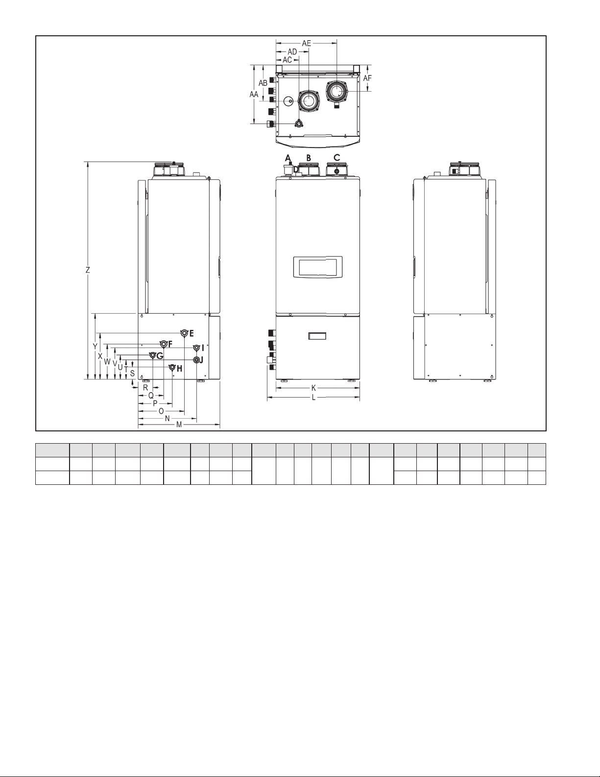
Figure 4 - Floor Model Dimensions
Table 11 - Floor Model Specications and Dimensions
the modulating range to ensure high reliability. The burner is
constructed of durable ceramic metal ber for long service life.
Appliance Sensors (Inlet – Outlet – Flue - Outdoor) - Sensors
provide highly accurate temperature monitoring to assure accurate
system control. These sensor inputs can be monitored through the
appliance control system and display.
Pressure Gauge – Allows the user to monitor system pressure.
System Safeties – The appliance is provided with many safety
features to ensure reliable and safe operation. Each safety is
connected to the appliance control. The appliance will alert the
user if an unsafe condition occurs and needs to be addressed. The
following are provided safeties: Flue Pressure Switch (monitors ue
pressure), Burner High Limit (monitors burner plate temperature),
High Limit Water Switch (monitors appliance temperature), Low
Water Sensor (monitors water level in the heat exchanger), optic
ame sensor (monitors ame quality), Flue Sensor (monitors ue
temperature), Condensate Pressure Switch (monitors pressure to
ensure condensation does not back up into appliance).
Manual Air Vent – Each appliance is equipped with an air vent to
discharge air from the system during start–up.
Intake and Exhaust Adapters – The appliance is equipped with
adapters to ease connection to the vent system. The adapters are
provided with clamps and seals to secure eld supplied piping, and
test ports to ease monitoring of the combustion system. Each appliance
is supplied with a 6 inch piece of CPVC that must be connected into the
exhaust vent adapter.
Appliance 1” Return and 1” Supply Connection – Appliances are
equipped with both top and bottom piping connections for greater
installation exibility.
Gas Connection – The appliance is equipped with a ¾” gas connection
to connect the incoming gas supply.
Field Wiring and Power Switch – Each appliance is supplied with a
power switch to cut o power. The appliance is also equipped with two
front mounted terminal strips. These terminal strips are separated into
low and line voltage to ease system wiring.
Condensate Trap and Hose Assembly – Each appliance has a built-
in condensate trap to control the discharge of condensate produced
by the appliance during normal operation. A corrugated condensate
hose is also provided to ensure proper drainage of condensate into
the pump or drain.
Low Water Cut O Probe – LWCO is provided with each appliance
to ensure the appliance has an adequate water level to eliminate
overheating and damge to the heat exchanger.
Pump Service Mode – Allows manual operation of pumps to
commission system and check pump operation.
Model K L M N O P Q R S T U V W X Y Z AA AB AC AD AE AF
140 17.3 19.1 16.8 12 9.5 7 5.3 3
2.5 4 5 6.5 7.3 9.5 13.5
44.8 12 7.4 4.7 6.8 12.6 5.5
199 19.7 21.5 18.2 13.3 10.8 8.3 6.6 4.3 48 14 8.5 3.2 9.2 15.1 5.2
Loading ...
Loading ...
Loading ...