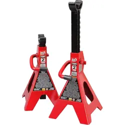
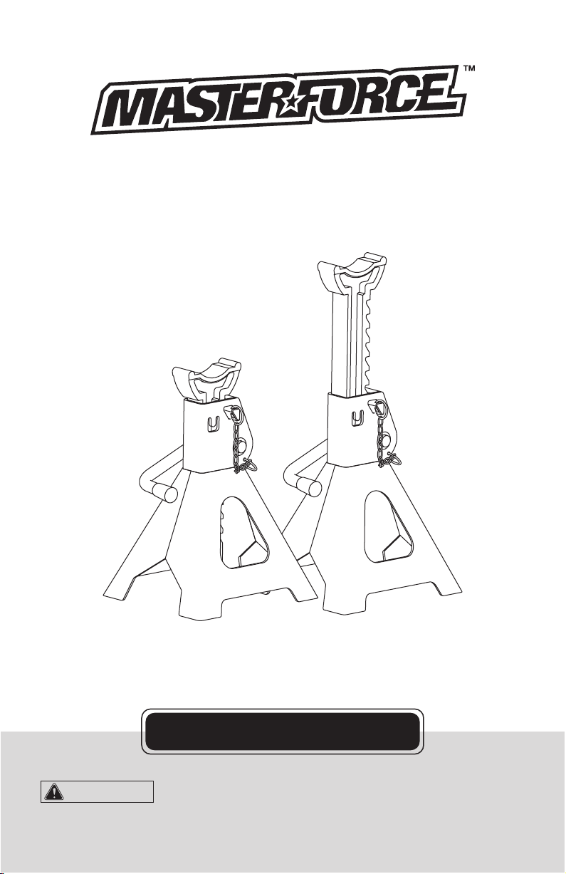
3 Ton Jack Stands
with Double Lock
260-2001
OPERATOR’S MANUAL
To Reduce The Risk Of Injury, User Must Read And
Understand Operator’s Manual. Save These Instructions For Future Reference.
CAUTION:

Page 1
TABLE OF CONTENTS
Safety Symbols ...................................................................................Page 2
Intended Use........................................................................................Page 2
Technical Specifications.....................................................................Page 2
General Safety Rules...........................................................................Page 3
Safety Markings...................................................................................Page 4
Assembly Instructions........................................................................Page 5
Operation Instructions........................................................................Page 6
Maintenance Instructions...................................................................Page 7
Assembly Diagram..............................................................................Page 8
Notes....................................................................................................Page 9
Warranty.............................................................................................Page 10

Page 2
SAFETY SYMBOLS
INTENDED USE
lbs Pounds
Warning symbol
Weight
Alerts user to warning messages
Read the operator’s
Manual
Wear safety glasses
To reduce the risk of injury, read
and understand operator’s manual
Operation of power tool can result in
foreign objects being thrown into eyes
Symbol Name Designation / Explanation
Some of the following symbols may be used on your tool. Please study them and learn their
meaning. proper interpretation of these symbols will allow you to operate the tool better and
safer.
Jack Stands are designed to support rated capacity, partial vehicle loads consisting of one end of
a vehicle. Use both stands for each operation.
TECHNICAL SPECIFICATIONS
Item Capacity
11-1/8
Lifting Range Min. (inch)
16-3/4
Lifting Range Max. (inch)
260-2001 3 TON

WARNING:
WARNING:
Page 3
GENERAL SAFETY RULES
EQUIPMENT USE AND CARE
1. Do not modify the jack stands in any way.
Unauthorized modification may impair the
function and/or safety and could affect the life
of the equipment. There are specific
applications for which the jack stands were
designed.
2. Always check of damaged or worn out parts
before using the jack stands. Broken parts will
affect the jack stands operation. Replace or
repair damaged or worn parts immediately.
3. Store idle jack stands. When jack stands
are not in use, store them in a secure place
out of the reach of children. Inspect it for good
working condition prior to storage and before
re-use.
INSPECTION
1. Inspect the equipment carefully before each
use. Ensure the equipment is not damaged,
excessively worn, or missing parts.
2. Do not use if components are bent, broken
or cracked.
3. Using equipment that is not in good clean
working condition may cause serious injury.
4. Inspect the work area before each use.
Make sure it is free and clear of any potential
hazards.
DO NOT OPERATE OR REPAIR THIS
EQUIPMENT WITHOUT READING THIS
MANUAL.
To maintain the equipment and user safety,
the responsibility of the owner is to read and
follow these instructions.
1. Inspect the equipment for proper operation
and function.
2. Keep instructions readily available for
equipment operators.
3. Make certain all equipment operators are
properly trained; understand how to safely and
correctly operate the unit.
4. Allow unit operation only with all parts in
place and operating properly.
5. Use only genuine replacement parts.
6. Service and maintain the unit only with
authorized or approved replacement parts;
negligence will make the equipment unsafe for
use and void the warranty.
7. Carefully inspect the unit on a regular basis
and perform all maintenance as required.
8. Store these instructions in the handle of
your equipment.
9. Keep all decals on the unit clean and
visible.
Read and understand all instructions. Failure to follow all instructions
listed below may result in serious injury.
WARNING:
NEVER use automotive
jack stands to support both ends, or one
side of a vehicle!
WARNING:
NEVER use on jack
stands on a lawn mower or lawn tractor.
Use only 1 pair per vehicle. Rated capacity
is per pair only!
CAUTION:
Do not allow persons to operate or assemble this jack until they have read
this manual and have developed a thorough understanding of how the jack works.
The warnings, cautions and instructions discussed in this instruction
manual cannot cover all possible conditions or situations that could occur. It must be
understood by the operator that common sense and caution are factors that cannot be built into
this equipment, but must be supplied by the operator.
IMPORTANT SAFETY CONSIDERATIONS

Page 4
SAFETY MARKINGS
1. Study, understand, and follow all instructions before operating this device.
2. Do not exceed rated capacity.
3. Use only on hard, level surfaces, with less than 3 degrees of slope.
4. Center load on saddle.
5. Use as a matched pair only.
6. Stands are not to be used to simultaneously support both ends of a vehicle.
7. No alterations shall be made to this product.
8. Support only on areas of the vehicle as specified by the vehicle manufacturer.
9. Only attachments and/or adapters supplied by the manufacturer shall be used.
10. Use wheel chocks or other blocking device on opposing wheels before using jack stands.
11. Do not use jack stands for any use other than the manufacturer specified usage.
12. Do not use if damaged in any way.
13. NEVER use jack stands on a lawn mower or lawn tractor.
14. Do not move or dolly the vehicle while on support stands.
15. Do not rock the vehicle while working on or around equipment.
16. The following are not recommended for supporting on this equipment: Foundations, Homes,
Mobile Homes, Trailers, RV’s, Campers, nor Fifth Wheels, etc...
17. Failure to heed these markings may result in personal injury and/or property damage.
WARNING:
DO NOT USE wood blocks or any other non-approved load sustaining
devices or any other non-approved supporting devices for a means of raising or supporting a
vehicle or load being raised. The manufacturer only warrants loads to be sustained by adapters or
accessories validated by the manufacturer. Failure to head these warnings may cause injury or
death.
Be sure all tools and personnel are clear before lowering load. Use only
attachments and/or adapters supplied by the manufacturer. Support only on areas of the vehicle
as specified by the vehicle manufacturer.
WARNING:
WARNING:
Training
Do not allow anyone who has not read this manual, and/or does not understand the requirements
to use the product.
Spectators
Do not allow bystanders around or under the load supported. Do not allow anyone in a vehicle
when raised or is supporting a load. Keep all bystanders away from lift when in use.
Operators
Not for use by children or people with reduced mental capacity.
NEVER use if incoherent or under the influence of medication, drugs or alcohol.
Inspection
Inspect the product carefully before each use. Ensure the product is not damaged, excessively
worn, or missing parts. Do not use the lift unless it is properly lubricated. Using a lift that is not in
good clean working condition or properly lubricated may cause serious injury.
GENERAL SAFETY INSTRUCTIONS:

Page 5
ASSEMBLY INSTRUCTIONS
In order to prevent removal of the post from the base use a hammer and flat end punch to hammer
the jack's tab in toward to post but not touching the post. Same stands are equipped with a bolt
instead of the tab. In this case the bolt can be threaded in toward the post until the bolt bottoms
out.
1. Install ratchet bar into frame (FIG.1) with
ratchet portion of bar aligned with locking pawl
(stopper).
2. Move the ratchet bar to its lowest position
by raising the locking handle, thereby releasing
the stopper, and guiding the bar downward
(FIG. 2).
FIG. 1 FIG. 2
3. Bend metal tab in (FIG. 3) using a hammer
and punch. This will help prevent inadvertent
separation of the ratchet bar from base frame.
4. Insert double locking pin (FIG. 4).
FIG. 3
FIG. 4
Metal tab
Double
locking pin

Page 6
OPERATION INSTRUCTIONS
• If the operator is not fluent in English, the
product and safety instructions shall be read
to and discussed with the operator in the
operator's native language by the
purchaser/owner or his designee, making sure
that the operator comprehends their contents.
• Visual inspection shall be performed before
each use of the stand by checking abnormal
condition, such as cracked welds, leaks and
damaged, loose, or missing parts if stand is
believed to have been subjected to abnormal
load or shock inspection shall be made by
authorized repair facility.
• Equipment that appears damage or worn or
operates abnormally shall be removed from
service.
TO LOWER LOAD
1. Ensure that all tools, equipment and
personnel are clear before lowering load.
2. With suitable jack, raise vehicle clear of
stands.
3. Carefully release stopper and allow ratchet
to glide down to lowest position.
4. Carefully remove stands, then carefully
lower vehicle with lifting device.
1. Use on hard level surface with less than 3
degrees of slope.
2. Raise vehicle with suitable jack.
3. Adjust height by pulling up on ratchet bar.
4. The weight of the locking handle should
secure the ratchet bar in desired position. To
confirm this, simply push down on the locking
handle. Check to ensure ratchet is secure
before loading.
5. Carefully position jack stands so that load is
centered on stand’s saddle.
6. Slowly lower the vehicle onto the stands.
7. Check to ensure vehicle is secure before
working on, around or under. When used to
support vehicle, use wheel chocks on all
unlifted wheels in both directions to prevent
inadvertent movement.
8. DO NOT jack or dolley while jack stands are
supporting the vehicle.

Page 7
MAINTENANCE INSTRUCTIONS
• Maintain your equipment. It is recommended
that the general condition of any equipment be
examined before it is used. Keep your
equipment in good repair by adopting a
program of conscientious repair and
maintenance. Have necessary repairs made
by qualified service personnel.
• Follow the maintenance instructions carefully
to keep your equipment in good working
condition. Never perform any maintenance on
the equipment while it is under a load.
Inspection
You should inspect the equipment for
damage, wear, broken or missing parts (e.g.:
pins) and that all components function before
each use. Follow lubrication and storage
instructions for optimum product performance.
Check the climbing pins to make sure that
they are not worn or damaged. Check that
everything is good working condition and that
nothing is blocking the holes. Do not use the
equipment unless it is in good working
condition.
Binding
If the equipment binds while under a load, use
equipment with equal or a larger load capacity
to lower the load safely to the ground. After
un-binding; clean, lubricate and test that
equipment is working properly. Rusty compo-
nents, dirt, or worn parts can be causes of
binding Clean and lubricate the equipment as
indicated in the lubrication section. Test the
equipment by lifting without a load. If the
binding continues, contact Customer Service.
IF YOUR EQUIPMENT BINDS
As your equipment becomes older, the
threads may start binding. This will prevent the
equipment from operating properly and safely.
Rusty threads, dirty threads, or a worn threads
a. All moving parts of the equipment should
be regularly cleaned.
b. Lubricate parts as required by the
manufacturer’s specifications. The type of
lubricant should be as specified by the
manufacturer or a qualified person.
Lubrication systems should be checked to
verify proper operation.
c. If additional maintenance is required, it
should be completed in accordance with the
instructions of the manufacturer or qualified
person.
can cause binding. Clean and lubricate the
lifting mechanism. Test the equipment without
a load. If the binding continues, refer to the
after sale parts and service. If your equipment
binds while under a load, use a equipment
with equal or larger load capacity to lower the
load safely to the ground. Repeat the steps in
this paragraph to the binding equipment.
Cleaning
If the moving parts of the equipment are
obstructed, use cleaning solvent or another
good degreaser to clean the equipment.
Remove any existing rust, with a penetrating
lubricant. Do not use motor oil or grease to
lubricate the equipment.
Rust Prevention
Check daily for any signs of rust or corrosion.
Without a load lift the equipment as high as it
goes and look under and behind the lifting
points. If signs of rust are visible clean as
needed.
Storing the Equipment
1. Store in a dry location, recommended
indoors.
2. Equipment should be stored in an area
where they will not be subjected to damage.
3. If extreme temperatures or chemically
active or abrasive environments are involved,
the guidance provided in shall be followed.
4. Temperature - Whene quipment is used at
temperatures above 140"F (60"C) or below
-20"F (-29"C), the equipment manufacturer or
a qualified person should be consulted.
5. Chemically Active Environments - The
strength and operation of eqipment can be
affected by chemically active environments
such as caustic or acid substances or fumes.
The equipment manufacturer or a qualified
person should be consulted before equipment
are used in chemically active environments.
6. Other Environments - The internal workings
of equipment can be affected by high
moisture, gravel or sand, silt, grit, or other
dust-laden air. Equipment subject to these
environments should have their inner
components frequently cleaned, inspected,
and lubricated.
Note: If the equipment is stored outdoors, be
sure to lubricate all parts before and after use
to ensure the equipment stays in good
working condition.

Page 8
ASSEMBLY DIAGRAM
Item Part#
1
2
3
4
5
6
7
1
1
1
1
1
1
1
T43002C-1
T43002-4
GB879-4x30
T42002-7
T42002-6
T46002C-3 (ASM)
Description Qty
Ratchet bar
Locking pawl
Spring pin Ø4x30mm
Locking handle
Handle sleeve
Base frame
Safety pin assembly
Safe Operating Temperature is between 40°F – 105°F (4°C - 41°C)

Page 9
NOTES

Page 10
For questions / comments, technical assistance or repair parts -
Please call toll free at: 1-888-448-6746 (M-F 8am - 5pm, Monday – Friday)
SAVE YOUR RECEIPTS
THIS WARRANTY IS VOID WITHOUT THEM
3-YEAR LIMITED WARRANTY
90-DAY MONEY BACK GUARANTEE
3 Ton Jack Stands with Double Lock
WARRANTY
This MASTERFORCE™ brand prouduct carries our famous No Hassle 3-Year Limited
Warranty to the original purchaser. If, during normal use, this MASTERFORCE™ prouduct
breaks or fails due to a defect in material or workmanship within three (3) years from
the date of original purchase, simply bring the tool with the original sales receipt back to
your nearest MENARDS® retail store. At its discretion, MASTERFORCE™ agrees to
have the tool or any defective part(s) repaired or replaced with the same or similar
MASTERFORCE™ product or part free of charge, within the stated warranty period,
when returned by the original purchaser with original sales receipt. Not withstanding the
foregoing, this limited warranty does not cover any damage that has resulted from abuse
or misuse of the Merchandise. This warranty: (1) excludes expendable parts including but
not limited to blades, brushes, belts, bits, light bulbs, and/or batteries; (2) shall be void if
this tool is used for commercial and/or rental
purposes; and (3) does not cover any
losses, injuries to persons/property or costs. This warranty does give you specific legal
rights and you may have other rights, which vary from state to state. Be careful, tools are
dangerous if improperly used or maintained. Seller’s employees are not qualified to
advise you on the use of this merchandise. Any oral representation(s) made will not be
binding on seller or its employees. The rights under this limited warranty are to the
original purchaser of the merchandise and may not be transferred to any subsequent
owner. This limited warranty is in lieu of all warranties, expressed or implied including
warranties or merchantability and fitness for a particular purpose. Seller shall not be
liable for any special, incidental, or consequential damages. The sole exclusive remedy
against the seller will be for the replacement of any defects as provided herein, as long
as the seller is
willing or able to replace this product or is willing to refund the purchase
price as provided above. For insurance purposes seller is not allowed to demonstrate
any of these power tools for you.
This MASTERFORCE™ brand prouduct carries our 90-Day Money Back Guarantee. If
you are not completely satisfied with your MASTERFORCE™ brand prouduct for any
reason within ninety (90) days from the date of purchase, return the tool with your
original receipt to any MENARDS® retail store, and we will provide you a refund - no
questions asked.

© 2010 Menard, Inc., Eau Claire, WI 54703 08/2019