Loading ...
Loading ...
Loading ...
MINI ULTRA ELECTRIC BOILERS Installation and operating manual (Revision: May 2015)
14
80F
27C
70F
21C
60F
15C
50F
10C
10F
-12C
40F
4C
30F
0C
20F
-7C
0F
-17C
-10F
-23C
-20F
-29C
70F/21C
80F/27C
100F/-38C
90F/32C
110F/43C
120F/49C
130F/54C
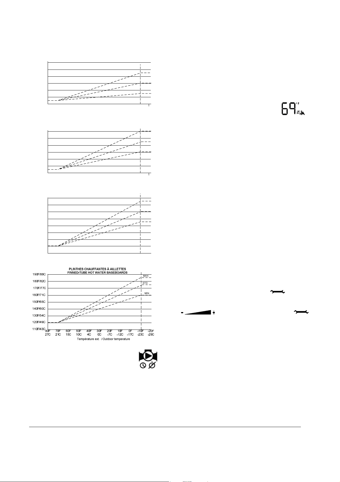
Température ext. / Outdoor temperature
Temp. de consigne / Target temp.
STD
MAX
MIN
PLANCHER CHAUFFANT DANS BÉTON
RADIANT FLOOR IN CONCRETE
80F
27C
70F
21C
60F
15C
50F
10C
10F
-12C
40F
4C
30F
0C
20F
-7C
0F
-17C
-10F
-23C
-20F
-29C
100F/-38C
90F/32C
110F/43C
120F/49C
130F/54C
Température ext. / Outdoor temperature
Temp. de consigne / Target temp.
STD
MAX
MIN
PLANCHER CHAUFFANT ENTRE SOLIVES
RADIANT FLOOR BETWEEN JOISTS
140F/60C
80F/27C
80F
27C
70F
21C
60F
15C
50F
10C
10F
-12C
40F
4C
30F
0C
20F
-7C
0F
-17C
-10F
-23C
-20F
-29C
100F/-38C
90F/32C
110F/43C
120F/49C
130F/54C
Température ext. / Outdoor temperature
Temp. de consigne / Target temp.
STD
MAX
MIN
RADIATEURS EN FONTE
CAST IRON RADIATORS
140F/60C
150F/65C
160F/71C
170F/77C
Temp. de consigne / Target temp.
4.6 PURGE DELAY OF THE PUMP
The controller offers the possibility to
stop the operation of the pump after an adjustable
delay once the heat demand has been completed.
The following choices are offered:
“OFF” The pump will stop immediately when the
heat demand has been satisfied. This selection
shall be selected on systems equipped with
motorised fast closing time zone valves with in
order to prevent noise from water hammering.
“15 sec to 60min”: delay where the pump will be
kept running to enable the pump to circulate
water into the system to equilibrate the heat in
all the building.
“ON”: The pump is in continuous operation.
Required on particular heating distribution
systems.
4.7 AUTOMATIC HEATING SHUT
DOWN
When the outdoor sensor is installed and that the
unit then operates in the “outdoor reset” mode, the
controller offers the user the possibility to
automatically stop the boiler when the outdoor
temperature reaches an adjustable value (0F (-17C)
à 105F (40C). This characteristic is especially
interesting on the following applications:
Heating systems equipped with many
thermostats where the user wants to prevent
the operation of the unit if one of the
thermostats has inadvertently been activated.
Heating systems where the owner supplies heat
to a lodger.
Systems connected to a geothermic heat pump
where we do not want the electric boiler to be
operating unless the outdoor temperature drops
to a selected degree.
4.8 CONFIGURATION OF THE
CONTROLLER
Since each type of heating distribution system is
designed to operate at water temperatures that are
particular to its operation, the proper configuration of
the operating parameters of this particular system is
important to maximize its performance.
In order to do this, the installer will access the
configuration menu by pressing the button for
2 sec. until the first menu appears. The selection of
the item or value is made by pressing the
button and by pressing the
button to get to the next menu. See table 1 below to
visualize the menu list that will gradually be
displayed.
If the buttons remain untouched for a period of 10
sec., the controller will register the value of the
selection made and return to the regular display
position. It will also return to the regular display after
reviewing all the operating parameters of the
controller.
In case of a power failure, the parameters will be
restored as they were established before the failure.
Loading ...
Loading ...
Loading ...