— WHATTODOIFYOUSMELLGAS
• OpenWindows
• DO NOTtrytolightanyappliance.
• DO NOTuseelectricalswitches.
• DO NOTuseanytelephoneinyourhouse.Immediatelycallyourlocalgassupplierfromaneighbor’stelephone.
Followthegassupplier’sinstructions.
• Do nottouchanyelectricalswitch;donotuseanyphoneinyourbuilding.
• Installationandservicemustbeperformedbyaqualifiedinstaller,serviceagencyorthegassupplier.
• Ifyoucannotreachyourgassupplier,calltheFireDepartment.
FOR YOUR SAFETY:
Donotstoreorusegasolineorotherflammablevaporsandliquidsinthevicinityofthisoranyotherappliance.
WARNING: Iftheinformationintheseinstructionsarenotfollowedexactly,afireorexplosionmayresultcausing
propertydamage,personalinjuryorlossoflife.
2016CB
Mr.Heater,Inc.,4560W.160THST.,CLEVELAND,OHIO44135•866-447-2194
WARNING: Improper installation, adjustment, alteration, service or maintenance can cause
property damage, injury, or death. Read the installation, operating and maintenance instructions
thoroughly before installing or servicing this equipment.
OPERATING INSTRUCTIONS
AND OWNER’S MANUAL
READ INSTRUCTIONS CAREFULLY:Readandfollowallinstructions.
Placeinstructionsinasafeplaceforfuturereference.Donotallowanyonewhohas
notreadtheseinstructionstoassemble,light,adjustoroperatetheheater.
LANGUAGES INCLUDED
•ENGLISH
•FRENCH
•SPANISH
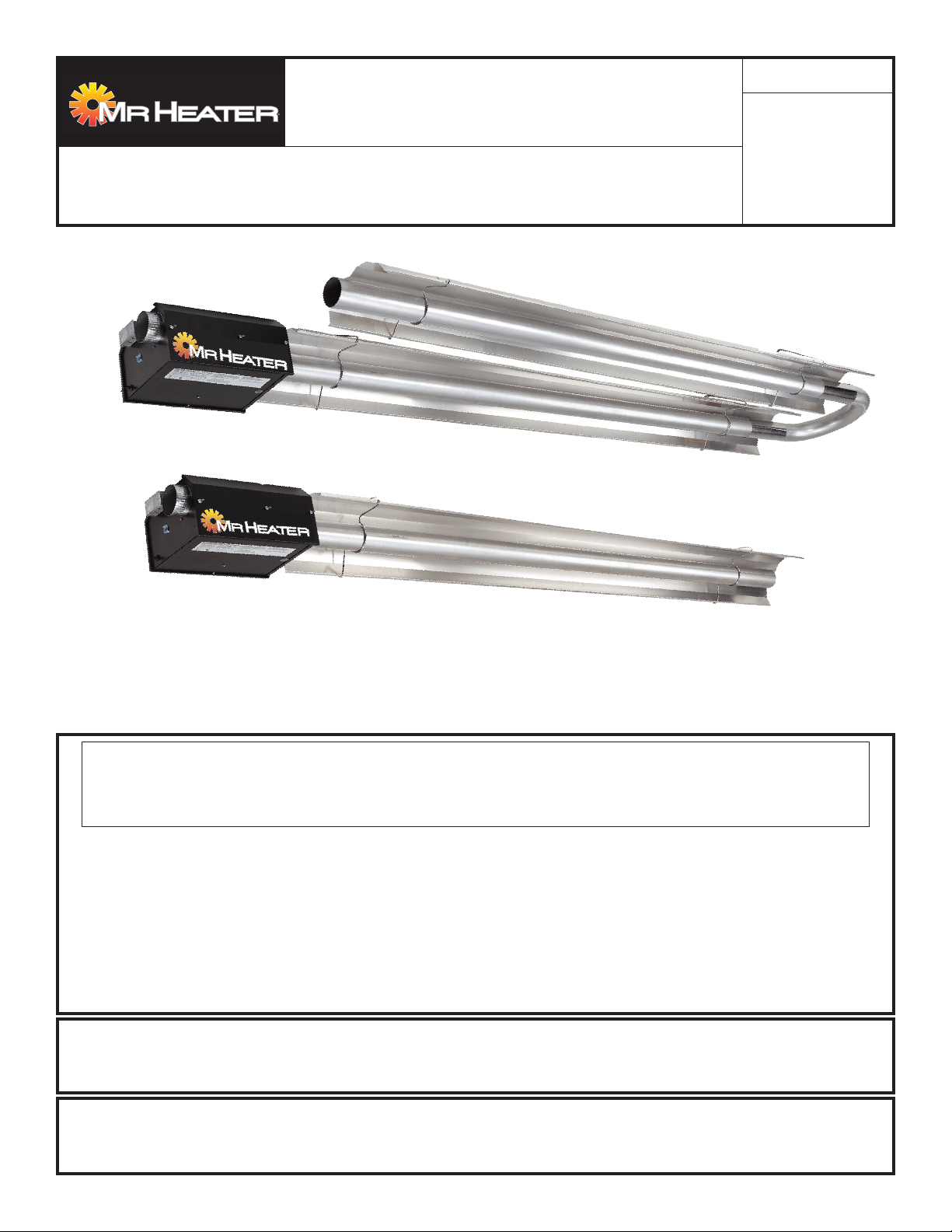
MR. Heater
Gas-Fired Low-Intensity Infrared Heaters Approved
For Residential Garage/Commercial Applications
40,000BTU60,000BTU
80,000BTU100,000BTU
125,000BTU150,000BTU
175,000BTU
MODELS
2
Mr. Heater Series Heater Operating Instructions and Owner’s Manual
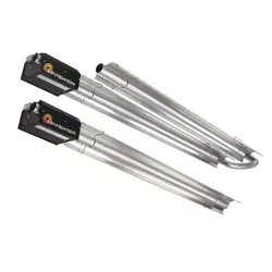
SECTION 1:Introduction
Mr.Heatermodelsarelow-cost,fieldassembledinfraredheaters
thatareeasytoinstallandrequireonlyminimalmaintenance.
Theyaredesignedtoprovideyearsofeconomicaloperationand
trouble-freeservice.
Checking Shipment
ChecktheshipmentagainsttheBillofLadingforshortages.
Also,checkforexternaldamagetocartons.Noteany
shortages,and/orexternaldamagetocartonsontheBillof
Ladinginthepresenceofthedeliverytrucker.Thedelivery
truckershouldacknowledgeanyshortagesordamageby
initializingthis“noted”BillofLading.Immediatelyreport
anyclaimsfordamagedmaterial,orshortagesthatwerenot
evidentatthetimeofshipment,tothecarrierandyourMr.
Heater,IncFactoryRepresentative.
Installer Responsibility
Allheatersandassociatedgaspipingshouldbeinstalledin
accordancewithapplicablespecificationsandthisinstallation
madeonlybyfirms(orindividuals)wellqualifiedinthistypeof
work.Consultlocalbuildinginspectors,FireMarshalsoryour
localMr.Heater,IncFactoryRepresentativeforguidance.
Mr.Heaterheatersareinstalledonthebasisofinformation
giveninalayoutdrawing,whichtogetherwiththecitedcodes
andregulations,comprisethebasicinformationneededto
completetheinstallation.Theinstallermustfurnishallneeded
materialthatisnotfurnishedasstandardequipment,andit
ishisresponsibilitytoseethatsuchmaterials,aswellasthe
installationmethodsheusesresultinajobthatisworkmanlike
andincompliancewithallapplicablecodes.
Mr.Heater,IncFactoryRepresentativeshavehadtrainingand
experienceintheapplicationofthisequipmentandcanbe
calledonforsuggestionsaboutinstallationwhichcansave
materialandmoney.
WARNING:
FIRE,BURN,INHALATION,ANDEXPLOSIONHAZARD.
KEEPSOLIDCOMBUSTIBLES,SUCHASBUILDING
MATERIALS,PAPERORCARDBOARD,ASAFEDISTANCE
AWAYFROMTHEHEATERASRECOMMENDEDBYTHE
INSTRUCTIONSNEVERUSETHEHEATERINSPACES
WHICHDOORMAYCONTAINVOLATILEORAIRBORNE
COMBUSTIBLES,ORPRODUCTSSUCHASGASOLINE,
SOLVENTS,PAINTTHINNER,DUSTPARTICLESOR
UNKNOWNCHEMICALS.
GENERAL HAZARD WARNING:
FAILURETOCOMPLYWITHTHEPRECAUTIONSAND
INSTRUCTIONSPROVIDEDWITHTHISHEATER,CAN
RESULTINDEATH,SERIOUSBODILYINJURYAND
PROPERTYLOSSORDAMAGEFROMHAZARDSOF
FIRE,EXPLOSION,BURN,ASPHYXIATION,CARBON
MONOXIDEPOISONING,AND/ORELECTRICALSHOCK.
ONLYPERSONSWHOCANUNDERSTANDANDFOLLOW
THEINSTRUCTIONSSHOULDUSEORSERVICETHIS
HEATER.
IFYOUNEEDASSISTANCEORHEATERINFORMATION
SUCHASANINSTRUCTIONSMANUAL,LABELS,ETC.
CONTACTTHEMANUFACTURER.
WARNING:
YOURSAFETYISIMPORTANTTOYOUANDTOOTHERS,
SOPLEASEREADTHESEINSTRUCTIONSBEFOREYOU
OPERATETHISHEATER.
CONTENTS
Section1INTRODUCTION.........................................................2
Section2PLANNING.................................................................3
Section3INSTALLATION&ASSEMBLY.......................................6
Section4EngineeringSpecifications.......................................13
Section5VENTING/DUCTING…………………………………………14
Section6GASPIPING..............................................................17
Section7WIRING....................................................................18
Section8OPERATIONMAINTENANCE.....................................19
Section8TROUBLESHOOTING.................................................21
Section9REPLACEMENTPARTS..............................................22
WARRANTYINFORMATION.....................................................28
WARNING:
The State of California requires the following warning:
COMBUSTIONBY-PRODUCTSPRODUCEDWHENUSING
THISPRODUCTCONTAINCARBONMONOXIDE,A
CHEMICALKNOWNTOTHESTATEOFCALIFORNIA
TOCAUSECANCERANDBIRTHDEFECTS(OROTHER
REPRODUCTIVEHARM).

3
Operating Instructions and Owner’s ManualMr. Heater Series Heater
SECTION 2: Planning
Thefollowingcodesandinstructionsshouldbefollowedwhen
planningtheinstallationoftheMr.Heaterheater.Inadditionto
theseinstructions,thewarningsin(Section1)mustbecarefully
adheredtosinceimproperinstallationmayleadtoproperty
damage,injury,ordeath.
National Standards and Applicable
Codes
Gas Codes:
Thetypeofgasappearingonthenameplatemustbe
thetypeofgasused.Installationmustcomplywithlocal
codesandrecommendationsofthelocalgascompany,
andtheNationalFuelGasCode,ANSIZ223.1–latest
revision,(sameasNFPABulletin54)ortheNaturalGas
andPropaneInstallationCode,CSAB149.1.
•Clearancebetweentheheateranditsventandadjacent
combustiblematerial(whichispartofthebuilding
oritscontents)shallbemaintainedtoconformwith
theStandardforInstallationofGasAppliancesand
GasPiping,NFPA-54/ANSIZ223.1–latestrevision,
NationalFuelGasCodeortheNaturalGasandPropane
InstallationCode,CSAB149.1.
Aircraft Hangers:
Installationinaircrafthangersmustbeinaccordance
withtheStandardforAircraftHangers,ANSI/NFPA-409
–latestrevision.
• Heatersinaircraftstorageorserviceareasshallbe
installedataheightof10feetabovetheuppersurface
ofwingsorengineenclosuresofthehighestaircraft
whichmaybehousedinthehanger.(Thisshouldbe
measuredfromthebottomoftheheatertothewingor
engineenclosure,whicheverishighestfromthefloor.)
• Inothersectionsofaircrafthangers,suchasshopsor
offices,heatersmustnotbeinstalledlessthan8feet
abovethefloor.
• Heatersinstalledinaircrafthangersshallbelocated
soasnottobesubjecttodamagebyaircraft,cranes,
moveablescaffoldingorotherobjects.
Public Garages:
Installationsingaragesmustbemadeinaccordance
withtheStandardforParkingStructures,NFPA-88A–
latestrevisionortheStandardforRepairGarages,NFPA-
88B–latestrevision.
• Heatersmustnotbeinstalledlessthan8feetabove
thefloor.Minimumclearancestocombustiblesmustbe
maintainedfromvehiclesparkedbelowtheheater.
• Wheninstalledoverhoists,minimumclearancesto
combustiblesmustbemaintainedfromtheuppermost
pointonthehoist.
Venting:
TheventingmustbeinstalledinaccordancewithNFPA-
54/ANSIZ223.1orCSA149.1–latestrevision,National
FuelGasCode.Partialinformationwithregardtothis
codeisprovidedin(Section5)ofthisinstallationmanual
withregardtosizeandconfigurationsforventing
arrangements.
• Anyportionoffluepipepassingthroughacombustible
wallmustbedualinsulatedorhaveanapprovedthimble.
RefertoANSI-Z223.1orCSA149.1–latestrevision.
Hazardous Locations:
Wherethereisthepossibilityofexposuretocombustible
airbornematerialorvapor,consultthelocalFireMarshal,
thefireinsurancecarrierorotherauthoritiesforapproval
oftheproposedinstallation.
Critical Considerations
Mr.Heaterisasuspendedheater.Therefore,itsstability,
flexibility,andsafetyareveryimportant.Beforestarting
installation,besurethesystemcanmeetthefollowing
requirements.
• Maintainspecifiedclearancestocombustibles,andsafe
distancefromtheheat-sensitivematerial,equipmentand
workstations.
• Thestatedclearancestocombustiblesrepresent
asurfacetemperatureof90°F(30°C)aboveroom
temperature.Buildingmaterialswithlowheattolerance
(suchasplastic,vinylsiding,canvas,etc.)maybesubject
todegradationatlowertemperatures.Itistheinstallers
responsibilitytoassurethatadjacentmaterialsare
protectedfromdegradation.
• Provideasuspensionwithverticallengthofchainor
swingingrodwhichhasatleast2inchesofhorizontal
travelforeachburnerinastraightrun.Besurethe
suspensionsystemissufficientlyflexibletoaccommodate
thermalexpansionwhichoccursasthesystemheatsup
(seeFigure6onpage12).
• Provideaccesstoburnersforservicing,preferableon
bothsides,aboveandbehindtheburnerforremoval.
• Provideaminimumof18inchesofclearancebetween
burnersandbuildingwalls.(Alwaysobserveminimum
clearancestocombustibles.)
• Besuretheheaterhasadownwardpitchofone-half
inchper20feetawayfromtheburner.
• Providesignsinstorageareastospecifymaximum
stackingheighttomaintainrequiredclearancesto
combustibles.
• Planlocationsupports(seeFigure2A-Fstartingonpage
8).Locateasupportnearallelbows.
• Theinstallationmustconformwithlocalbuildingcodes
orintheabsenceoflocalcodes,withtheNationalFuel
GasCode,ANSIZ223.1/NFPA54ortheNaturalGas
andPropaneInstallationCode,CSAB149.1.
• Ifanexternalelectricalsourceisutilized,theheater,
wheninstalled,mustbeelectricallygroundedin
accordancewiththeNationalElecticalCode,ANSI/
NFPA70orcurrentCanadianElectricalCode,CSA
C22.1.
4
Mr. Heater Series Heater Operating Instructions and Owner’s Manual
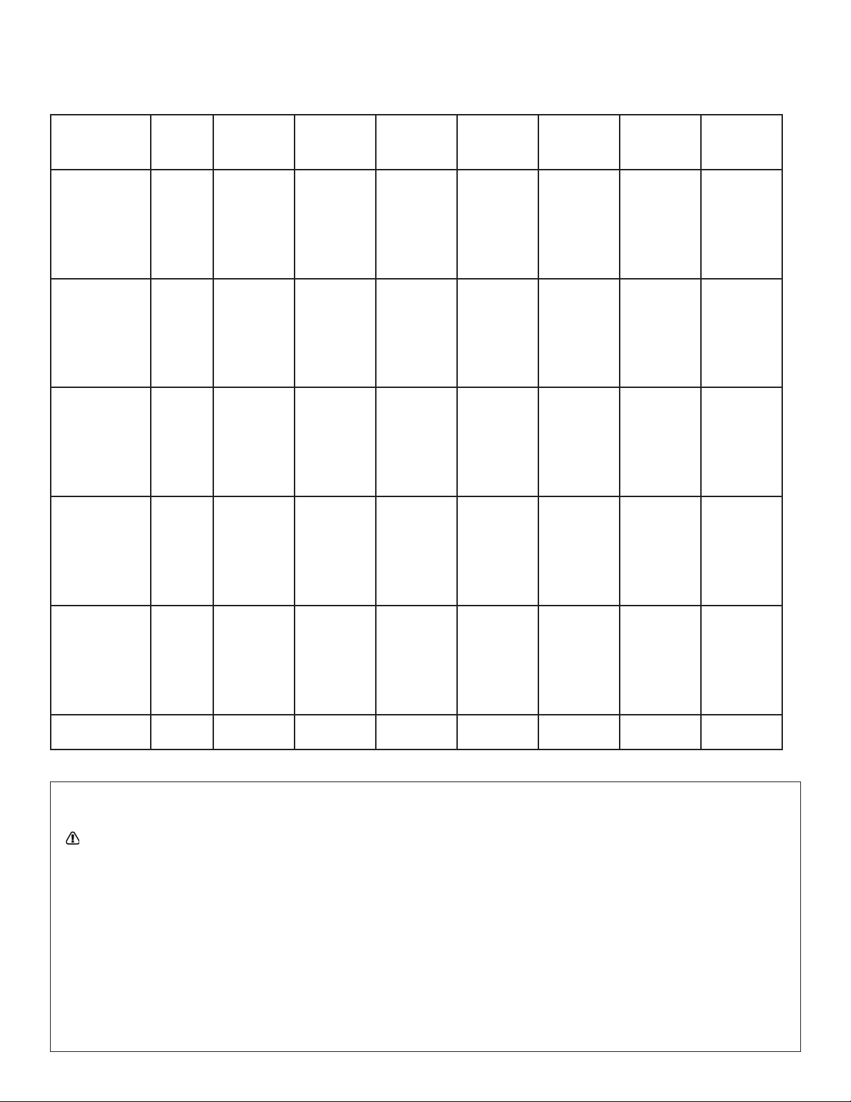
Clearances To Combustibles
TABLE 1:MinimumClearancestoCombustibles(UseFigure1onpage5asaGuide)
Reflector Type Position
40,000
BTU
60,000
BTU
80,000
BTU
100,000
BTU
125,000
BTU
150,000
BTU
175,000
BTU
Standard
Reflector
(Horizontal)
A
B
C
D
6”
30”
55”
30”
6”
30”
55”
30”
6”
36”
55”
36”
6”
36”
74”
36”
6”
36”
87”
36”
6”
36”
87”
36”
8”
36”
87”
36”
45°ReflectorTilt
A
B
C
E
F
12 ”
30”
55”
36”
60”
12 ”
30”
55”
36”
60”
18”
36”
55”
36”
60”
18”
36”
74”
36”
60”
18”
36”
87”
36”
60”
18”
36”
87”
36”
60”
18”
36”
87”
36”
60”
U-TubeStandard
(Horizontal)
A
B
C
D
6”
30”
55”
30”
6”
30”
55”
30”
6”
36”
55”
36”
6”
36”
74”
36”
6”
36”
87”
36”
6”
36”
87”
36”
8”
36”
87”
36”
U-TubeOpposite
45°
A
B
C
F
12 ”
30”
55”
60”
12 ”
30”
55”
60”
18”
36”
55”
60”
18”
36”
74”
60”
18”
36”
87”
60”
18”
36”
87”
60”
18”
36”
87”
60”
U-TubeFull45°
A
B
C
E
F
12 ”
30”
55”
36”
60”
12 ”
30”
55”
36”
60”
18”
36”
55”
36”
60”
18”
36”
74”
36”
60”
18”
36”
87”
36”
60”
18”
36”
87”
36”
60”
18”
36”
87”
36”
60”
Unvented AboveA 36” 36” 36” 36” 36” 36” 36”
WARNING:
FIRE OR EXPLOSION HAZARD
CAN CAUSE PROPERTY DAMAGE, SEVERE INJURY OR DEATH.
Inallsituations,clearancestocombustiblesmustbemaintained.Failuretoobserveclearancestocombustiblesmayresultinproperty
damage,severeinjury,ordeath.
Minimumclearancesmustbemaintainedfromvehiclesparkedbelowtheheater.Signsshouldbepostedinstorageareastospecify
maximumstackingheighttomaintainrequiredclearancestocombustibles.
Cautionshouldbeusedwhenrunningthesystemnearcombustiblematerialssuchaswood,paper,rubber,etc.Considerationshouldbe
giventopartitions,storageracks,hoists,buildingconstruction,etc.
TABLE1givesminimumacceptableclearancestocombustibles.ClearancesasshowninTABLE1arenotforuseinfour-sidedenclosures.
5
Operating Instructions and Owner’s ManualMr. Heater Series Heater
Clearances To Combustibles
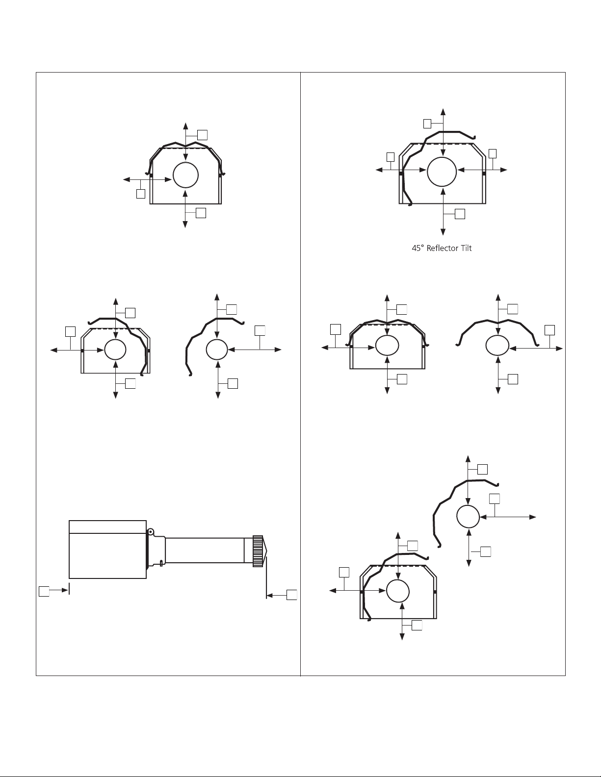
Figure 1: ClearancesToCombustibles(RefertoTABLE1onpage4)
A
C
E
F
STANDARD REFLECTOR
D
A
C
A
C
D
“U”-Tube,Standard
A
C
D
F
“U”-Tube,Opposite45°
F
C C
A
A
E
A
F
“U”-Tube,Full45°
C
A
C
B
B
FrontandBackClearance
6
Mr. Heater Series Heater Operating Instructions and Owner’s Manual
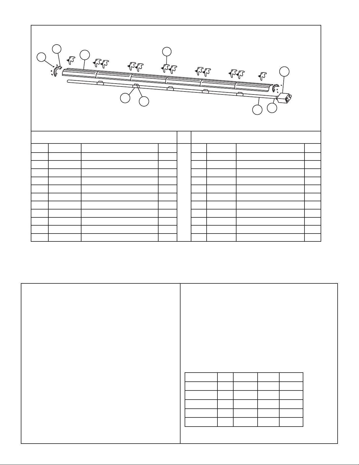
SECTION 3: Installation & Assembly
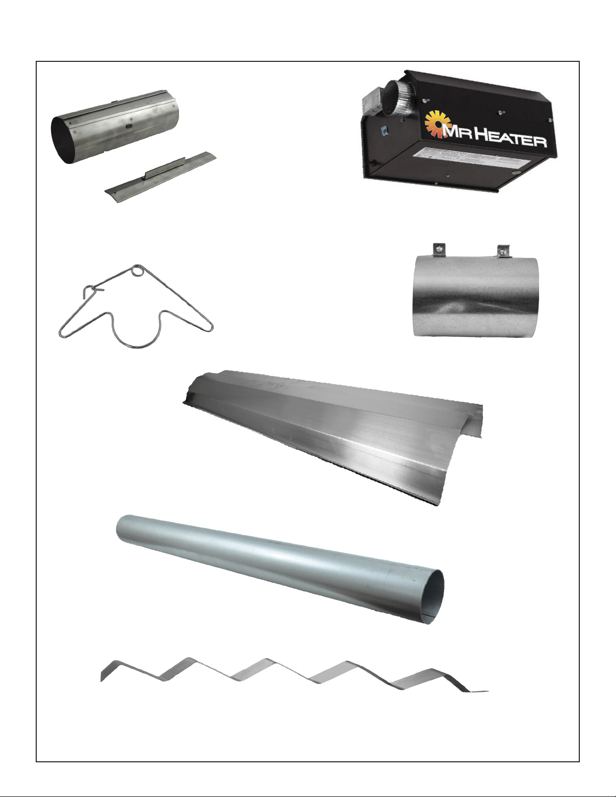
TUBECOUPLING(14612)
KEYFORTUBECOUPLING
(14616)
TUBEHANGER
(14585P)
HEATEXCHANGERTUBE10'
(06413)
TURBULATORBAFFLE10'(03445)
TURBULATORBAFFLE5'(03447)
**NOTINCLUDEDWITHALLMODELS**
**ONLYHEATERS30'LENGTHANDUNDER**
REFLECTOR10'
(00418A)
VENTADAPTER
(19021)
BURNERBOX

7
Operating Instructions and Owner’s ManualMr. Heater Series Heater
Installation Procedure
Takemaximumadvantageofthebuildingupper
structure,beams,joists,purlins,etc.,fromwhichto
suspendtheheater.Thereisnouniquesequencefor
installationofthetubing.On-siteobservationwillusually
revealalogicalsequence.Begintheinstallationatthe
mostcriticaldimension.Thiscouldsavetime.Watchfor
swingingdoors,overheadcranes,carliftsetc.Reflectors
andtubingcanbeinstalledasyoumovealong.Carefully
adjustsystempitchateachpositiontoleveltheheater.
Pitchdownone-halfinchin20feet(awayfromburner).
DON’TPressuretestthegaslineusinghighpressure(greater
than½PSIG)withoutclosingthehigh-pressureshutoff
cocks.Failuretodosowillresultindamagetothe
burners.
DO Familiarizeyourselfwithlocalandnational
codes.
Burner Housing
Mustalwaysbe
installedhorizontally.
Tube and Reflector Hanger
Installimmediatelyafterfirst
coupling.
Turbulator Assembly
Mr.Heater,IncnormallyshipsMr.Heaterheaterswith
turbulatorsassembledintoappropriatetubes.
Tube and Reflector Hanger
Suspendsystemfromthesehangers.
Minimumtwo(2)requiredpertube.
Reflectors
Alternateoverlapasshown
onoverview.Lengthof
reflectorandamountof
overlapisindicated.
10'2-1/2"
ALUMINIZED
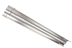
Heat Exchange Tubes
Suppliedin10ft.lengths.
Tube Coupling Assembly
Couplingshouldbeorientedwith
slidebarontop,andallcouplings
should“point”inthesamedirection.
Where Field Changes Occur
TurbulatorSectionsandAdapterareavailablein
sectionsandmustbeassembledbeforeinstallation
(SeeFigure3fordetails).Thenumberofsections
requiredisindicated.
AssembletheheatercomponentsasshowninFigures2A,2B,2C,2D,2E,2Fand2G.Optionalreflectorconfigurationsareshownin(Figure
1).Installappropriatedsuspensionhardware,beamclamps,chainorrodatpredeterminedlocations.Adjustmentofchainlengthwillprovide
uniformpitch.
Developaplannedprocedurewhichwillconservematerial
andlaboronthejob.
Checktoseethatallmaterialandequipmentisonthejob
beforestartinginstallation.
Allowforthermalexpansionofthehottube.
Installthegasconnectoronlyasshownininstructions(see
Figure14onpage17).
Haveslipjointswhererequiredbetweenreflectorstokeep
themfrombucklingorcomingapart.
Provide1sq.inchoffreeairopeningtoeach1,000BTU/hr.
ofheaterinput(butnotlessthan100sq.inches)inenclosed
spaces.Oneopeningshouldbewithin12inchesofthetop
andonewithin12inchesofthebottomoftheenclosure.
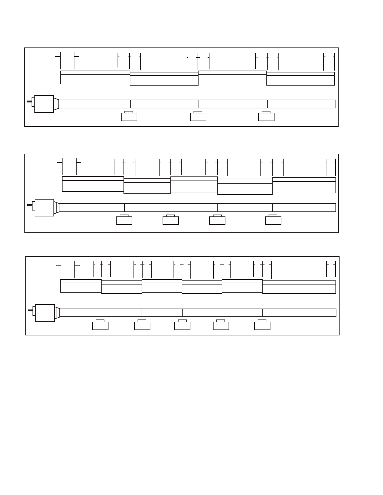
FIGURE 2: MR. Heater Overview
Vent Adapter
Usedtoattachtheheat
exchangertubingtoventpipe.

8
Mr. Heater Series Heater Operating Instructions and Owner’s Manual
HANGER HANGER
18” 18”
10’ 2-1/2”
ALUMINIZED
AL
UMINIZED
FIGURE 2B: MR. Heater Model 60,000 & 80,000 BTU, Assembly Overview
20 ft. Exchanger length. 21 ft. - 4 in. Total Heater length. 4 Suspensin points indicated.
FIGURE 2A: MR. Heater Model 40,000 BTU
10 ft. Exchanger length. 11 ft. - 4 in. Total Heater length. 2 Suspension points as indicated.
HANGER HANGER HANGER HANGER
18” 18” 18” 18”
10’ 2-1/2”
10’ 2-1/2”
ALUMINIZED
2-1/2” OVERLAY TYP
(1) Turbulator Sections
ALUMINIZED
FIGURE 2D: MR. Heater Model 100,000 BTU Assembly Overview
30 ft. Exchanger length. 31 ft. - 4 in. Total Heater length. 6 Suspension points as indicated.
FIGURE 2C: MR. Heater Model 80,000 BTU, Assembly Overview
30 ft. Exchanger length. 31 ft. - 4 in. Total Heater length. 6 Suspension points as indicated
18” 18” 18” 18” 18” 18”
10’ 2-1/2”
10’ 2-1/2”
10’ 2-1/2”
(1) Turbulator Sections
HANGER HANGER HANGER
Typ.
HANGER
ALUMINIZED ALUMINIZED
9' Long Turbulator Section
10' Long Turbulator Section
5' Long Turbulator Section
10' Long Turbulator Section
9
Operating Instructions and Owner’s ManualMr. Heater Series Heater
FIGURE 2E: MR. Heater Model 100,000 & 125,000 BTU
40 ft. Exchanger length. 41 ft. - 4 in. Total Heater length. 8 Suspension points as indicated.
FIGURE 2F: MR. Heater Model 125,000 , 150,000, 175,000 BTU
50 ft. Exchanger length. 51 ft. - 4 in. Total Heater length. 10 Suspension points as indicated.
FIGURE 2G: MR. Heater Model 150,000 & 175,000 BTU
60 ft. Exchanger length. 61 ft. - 4 in. Total Heater length. 12 Suspension points as indicated.
10’ 2-1/2” 10’ 2-1/2”
10’ 2-1/2”
10’ 2-1/2”
10’ 2-1/2”
18”
Typ.
ALUMINIZED ALUMINIZED ALUMINIZED ALUMINIZED ALUMINIZED
18” 18” 18” 18” 18” 18” 18” 18” 18”
10’ 2-1/2” 10’ 2-1/2” 10’ 2-1/2”
10’ 2-1/2” 10’ 2-1/2” 10’ 2-1/2”
18”
Typ.
ALUMINIZED ALUMINIZED ALUMINIZED ALUMINIZED ALUMINIZEDALUMINIZED
18” 18” 18” 18” 18” 18” 18” 18” 18” 18” 18”
ALUMINIZED ALUMINIZED ALUMINIZED ALUMINIZED
18”
Typ.
18”
18”
18”
10’ 2-1/2”
10’ 2-1/2”
10’ 2-1/2”
10’ 2-1/2”
18"
18"
18"
18"
18"
18"
18"
10
Mr. Heater Series Heater Operating Instructions and Owner’s Manual
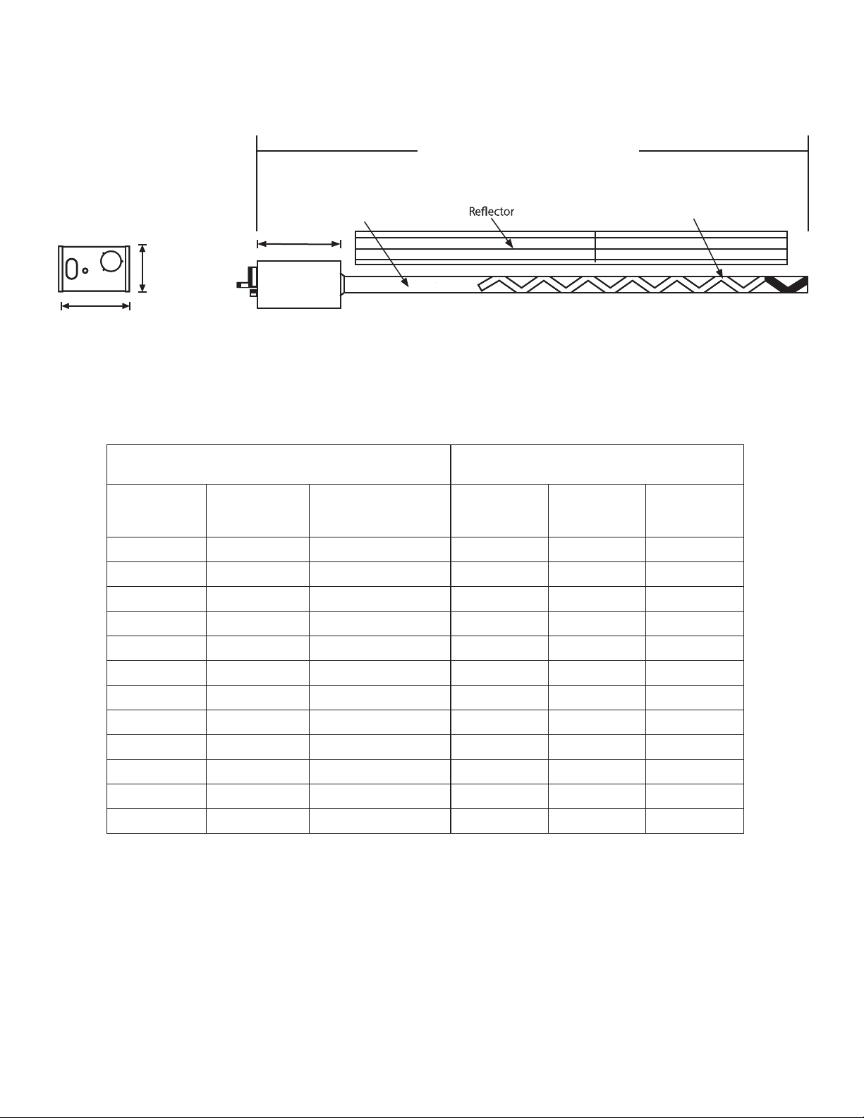
FIGURE 3: MR. Heater Dimensions & Suggested Mounting Heights
(someModels)
Turbulator
HeatExchanger
Tubing
(someModels)
Turbulator
HeatExchanger
Tubing
MinimumTotalLength(seechartbelow)
Burner Side View
Burner Ratings and Heat Exchanger Lengths: (NG and LP) Suggested Mounting Heights
Rate (BTU/Hr.)
Heat Exchanger
Length
Turbulator
Minimum
Total Length
Suggested
Min. Space
Typical
Mounting
Height Spot
40,000 10ft. 9ft.
10'-4' 8'-10' 10’-14'
60,000 20ft. 10ft.
21'-4' 10’-12’ 10’-14’
80,000 20ft. 10ft.
21'-4' 12’-15’ 12’-15’
80,000 30ft. 10ft.
31'-4' 12’-15’ 12’-15’
100,000 30ft. 5ft.
31'-4' 12’-15’ 12’-15’
100,000 40ft. None
41'-4' 15’-18’ 12"-15'
125,000 40ft. None
41'-4' 15’-20’ 14’-19'
125,000 50ft. None
51'-4' 15’-18’ 14’-19'
150,000 50ft. None
51'-4' 20’-23’ 15’-25'
150,000 60ft. None
61'-4' 20’-25’ 15’-25'
175,000 50ft. None
51'-4' 20’-23’ 15’-25'
175,000 60ft. None
61'-4' 20’-25’ 15’-25'
Burner Rear View
9.25"(23.49cm)
9.25"(23.49cm)
17.75"(45.08)
11
Operating Instructions and Owner’s ManualMr. Heater Series Heater
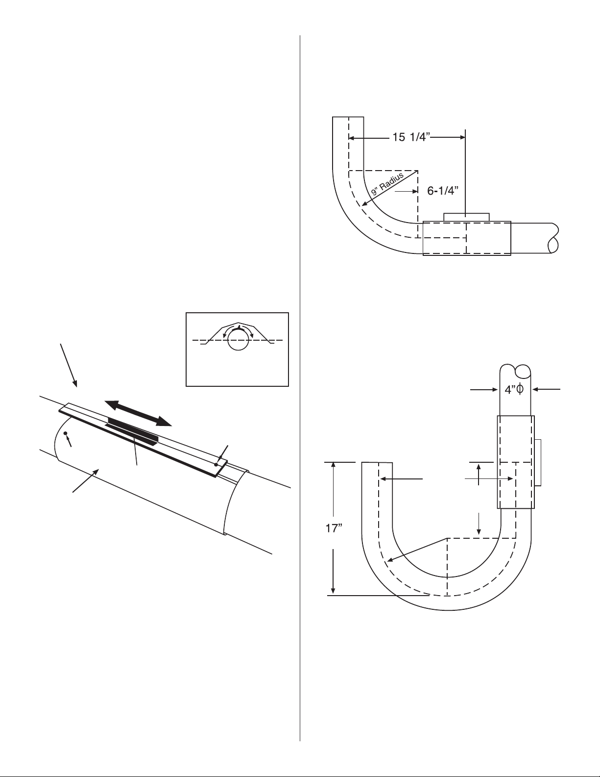
Couplings: Tubeandtubefittingsareconnectedbywrap-
aroundcouplingswhichclampbymeansof
atapered,hammer-drivenlockmember.The
startingendsofthecouplingandlockmember
areidentifiedby1/4”holeswhichareput
togetherwhenstartingassembly.Besurethe
tubeendsareinlineandtubeendsbuttagainst
stoppin(s)insidecoupling.Theslidebaristobe
hammer-driventoapointofsecuringthecoupling
snuglytothetubes.Over-drivingwillresultin
distortionofthecouplingorslidebarliptoa
pointdecreasingtheholdingthecapabilityofthe
coupling.(SeeFigure4)
ElbowFittingDimensions
FIGURE 5: Installation of Elbow & Coupling
ElbowPackage: Stk.#F106415ElbowPackageincludes:
(1)elbow,(1)coupling.Installelbow
intoradianttubesequencewhereplans
indicatea90°bend(seeFigure4).
U-TubeFittingDimensions 180°U-Tube
Stk.#i ncludes:F106414U-TubePackage
radianttubesequencewhereplans
indicatea180°bend
(seeFigure4).
COUPLING ASSEMBLY
Plain Coupling - 14612
Key for Coupling - 14616
Tighten
Loosen
Hole 1
Coupling
Assembly
Impact
Block
Hole 2
Whenassemblingcouplingnote
thelocationofHole1andHole2
Orientcouplingsothat
theimpactblockisabove
tubecenterline.
TUBECOUPLING
KEYforCOUPLING
FIGURE 4:
(38.73 CM)
(15.24 CM)
18" (45cm)
10"
(25cm)
(10cm)
(43cm)
9"
(22cm)
Radius
90°
(1) U-tube, (1) coupling
Install U-tube elbow into
12
Mr. Heater Series Heater Operating Instructions and Owner’s Manual
A
Chainkit-Stk.#17370
Onechainkitwillsuspendone10ft.sectionoftubeandone10ft.
sectionofreflector.
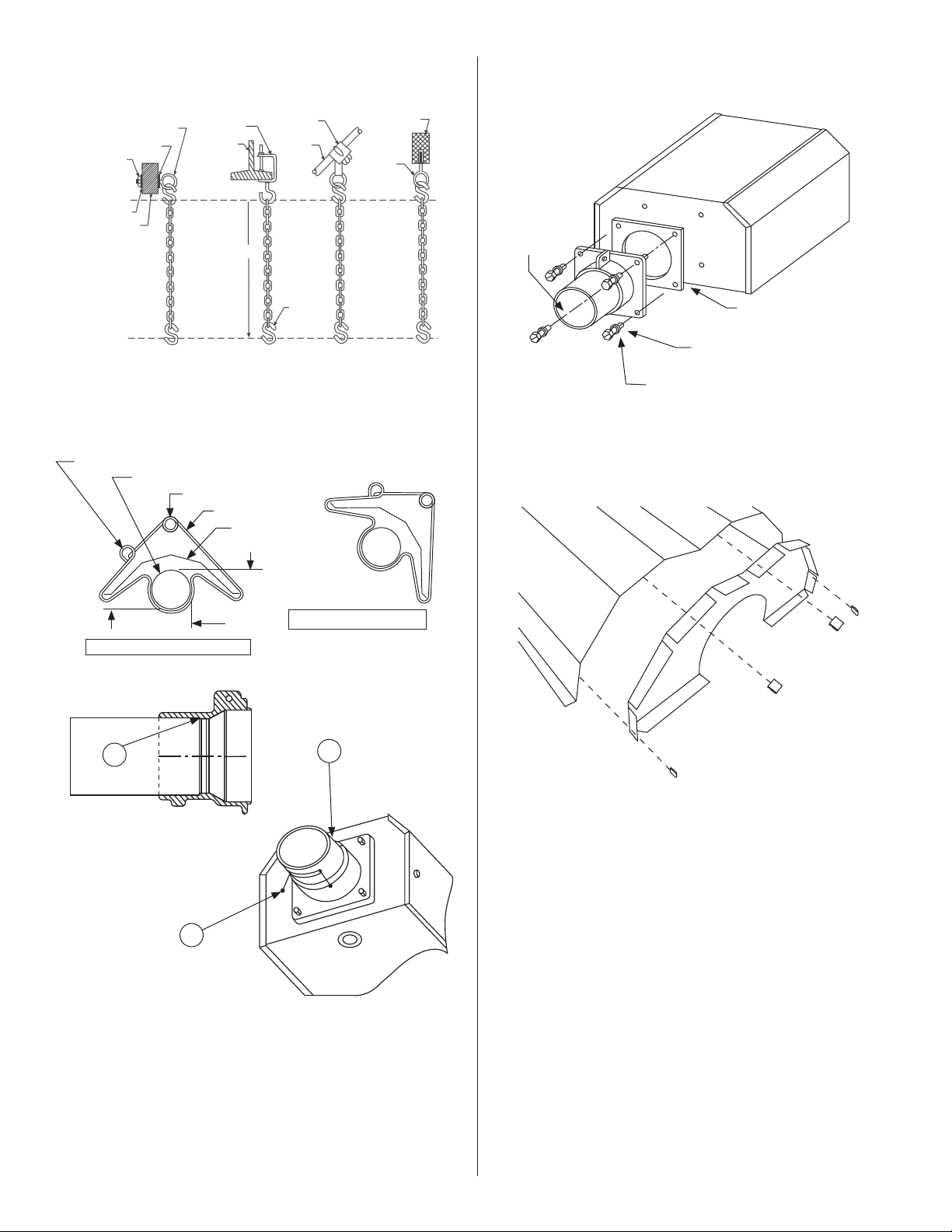
FIGURE 7: Tube and Reflector Hanger
FIGURE 7: Mounting Flange / Tube Detail
1) Inserttube06413intofrontcastingtopoint(A).
2) Tighterallsetscrewsmarked(B)untilsnug.
3) Afterbothsetscrewsaresnug,turneach
additional1/4turntosecuretubeinplace.
FIGURE 8: Burner Box / Transition Tube Detail
FIGURE 6: Typical Suspension Details
Locknut
Washer
WoodBeam
Washer
ScrewHook
min.3/8"(10mm)
I-Beam
Beam
Clamp
AsReq'd
S-Hook
BarJoist
Clip
Truss
Concrete
Beam
Anchor
MountingFlange
CapScrew
Stk.98012
SplitLockWasher
Stk.#98527
Gasket
Stk.#12397
Burner Box
(flameobservation
windowfacingdown)
horizontal reflector position (standard)
angle mounting ring
radiant tube
horizontal mounting ring
hanger
reflector
top
side
45° reflector position (optional)
below
FIGURE 9: Reflector End Cap
Partslist
100419ReflectorEndCap(Qty1)
209369SpringClip(Qty4)
FlangeKit#06428XL
KitIncludes:Flange,Screws(4),LockWashers(4),Gasket(1)
B
B

13
Operating Instructions and Owner’s ManualMr. Heater Series Heater
SECTION 4
Engineering Specifications
ThetotalheatingsystemsuppliedshallbedesigncertifiedbyCSA
underANSIZ83.20alatestrevisionandCGA2.34alatestrevision.
A. Burner & Burner Controls
1.Burnersshallbecapableoffiringwithoneofthefueloptionsas
specifiedonthepurchasedocuments:NaturalGasorLP.
2.Burnersshallbesuppliedtofireatanyoneoftheinputratesas
specified.
40,000BTU/Hr. 125,000BTU/Hr.
60,000BTU/Hr. 150,000BTU/Hr.
80,000BTU/Hr. 100,000BTU/Hr.
175,000BTU/Hr.
3.Burnershallbeequippedwithadirectsensesilicon-carbidehot
surfaceignitioncontrolsystemwith100%shut-offignitiondevice.
Powersuppliedtoeachheatershallbe120V,60Hz,singlephase.
Burnersshallberatedfor1.0Amp(run)and5.0Amp(start.)
4.Burnershallbeequippedwiththermaloverloadmotor
protection,balancedairrotor,combustionairprovingsafety
pressureswitch,andviewingwindowforflameobservation.
5.Whenspecified,incontaminatedenvironments,theburnershall
becapableofsupplyingoutsideairtoeachburnerforthesup-
portofcombustion.
6.Allburnersshallbepre-wiredwithagroundedelectrical
cordandplug.
7.Atcustomer’schoice,burnersmaybecontrolledwitheither
anoptionallinevoltagethermostatorbyoptionallowvoltage
thermostatswithanappropriatelowvoltagetransformerrelay.
8.Gassupplytotheburnersshallconformtothefollowing:
1/2”NPTgasconnectorsize
NaturalGas: 4.6”W.C.MIN,7.0”W.C.MAX
LPGas: 11”W.C.MIN,14.0:W.C.MAX
B. Heat Exchanger
1.Radianttubingshallbe4”diameteraluminizedsteelsuppliedin
10ft.sections.Sectionsshallbejoinedwithstainlesssteelwrap-
aroundcouplings.
2.Reflectortobeofaluminummaterialanddesignedtodirectall
radiantoutputbelowhorizontalcenterlineofradianttube.
3.Heatersshallbeventedaccordingtomanufacturer’s
recommendations.
Gas pressure at MANIFOLD:
Natural Gas: 3.5” W.C.
LP Gas: 10.5” W.C.
1/2”NPTGasConnectorSize
Gas INLET pressure:
Natural Gas: 4.6” W.C. Min
11.0” W.C. Max
LP Gas: 11.0” W.C. Min
14.0” W.C. Max
1/2”NPTGasConnectorSize
Electrical Rating:(AllModels)
120V-60Hz
1.0AMP(Run)5.0AMP(Start)
Dimensions:
Flue Connection Size…………………4”
Outside Air Connection Size………4”
14
Mr. Heater Series Heater Operating Instructions and Owner’s Manual
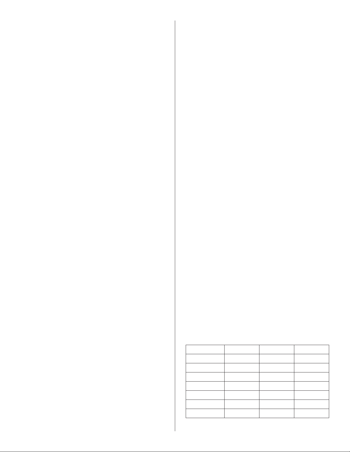
COMMON VENTING - (2) Heaters (Horizontal and Vertical)
Model# H=6ft. H=8ft. H=15ft.
40,000BTU D=7" D=6" D=6"
60,000BTU D=7" D=6" D=6"
80,000BTU D=8" D=7" D=6"
100,000BTU D=8" D=8" D=7"
125,000BTU D=10" D=10" D=8"
150,00BTU D=10" D=10" D=8"
175,000BTU D=10" D=10" D=8"
SECTION 5
Venting / Ducting
General Requirements
Thisheatermustbeventedinaccordancewiththespecifications
containedinthismanualandwiththefollowingnationalcodes
andanystate,provincialorlocalcodeswhichmayapply:
•RefertoNationalFuelGasCodeNFPA54/ANSIZ223.1-latest
revision.
•CANADA:RefertoNaturalGasandPropaneInstallationCode
CSAB149.1-latestrevision.
Theheatermaybeventedtotheoutdoorseitherverticallyor
horizontally.
Optionaloutsideairsupplymaybedirectedtotheheater
horizontallyorvertically.
Besurethatthemethodselectedforventingheatercomplies
withallcodesasrequiredforeachparticularlocation
Theuseofsingle-wallventpipe(26gauge)isrecommended.A
sectionofdouble-wallventpipeisrecommendedwhenpassing
throughtherooforwall.
Exhaustendofheaterwillaccepta4'(10cm)ventpipeusing
theventadapter.Installtheventadapterwiththeseamontop,
secureallventjointswithaminimumof3#8x3/8"sheetmetal
screwsandsealalljointsusingahightemperaturesilicone
sealant.
Ifcondensationintheflueisaproblem,thefluelengthshould
beshortenedorinsulated.
Ventpipemustbeslopeddownwardawayfromtheburner
1/4"(.6cm)forever10'(3m).
VENTLENGTHS:
• Maximumtotalventlengthallowedinthirty(30’)feet.
• Maximumoutsideairsupplyductallowedthirty(30’)feet.
• Maximumtotalventlengthplusoutsideairsupplylength
shallnotexceedfifty(50’)feet.
NOTE:
Atotaloftwo(2)elbowsareallowedforventand
outsideairsupplycombination.Subtract5'feetperadditional
elbowfrommaximumlengthallowedif3ormoreelbowsare
used.
Installaminimum18"(30cm)straightlengthofductforair
intakeorventbeforeanyTeeorelbow.
Alternative Arrangements / Optional Equipment for Venting
Unvented Operation
a) Sufficientventilationmustbeprovidedintheamountof4
CFMper1,000BTU/hr.firingrate.
b) RefertoANSIZ223.1-latestrevision,NFPA-54andlocal
codesforadditionalinformation.
c) Useofoptionaloutsidecombustionairisnotrecommended
withunventedheatersduetopressureconsiderations.Refer
topage16
Horizontal Venting
a) Four(4”)inchO.D.fluepipeisrequired.Thirty(30’)feet
maximumlengthisrecommended.
b) Allfluejointsshouldbesealedusingsuitableproductsuch
asGeneralElectricRTV106orPermatexForm-A-GasketRed
HighTemperatureSiliconeAdhesiveSealant.
c) Donotinstallanyelbowor45fittingtobringventlower
thanthehorizontaltubesystem.
d) Ventterminalshouldbeinstalledataheightsufficientto
preventblockagebysnow.
1) Ventmustexitbuildingnotlessthanseven(7’)feet
abovegradewhenlocatedadjacenttopublicwalkways.
2) Ventmustterminateatleastthree(3’)feetaboveany
forcedairinletlocatedwithintenfeet(10’).
3) Ventmustterminateatleastfour(4’)feetbelow,four
(4’)feethorizontallyfrom,orone(1’)footaboveany
door,window,orgravityinletintoanybuilding.
4)Ventterminalshallbelocatedatleasttwelve(12”)inches
fromanyopeningthroughwhichventgasescouldenter
thebuilding.
5) Ventterminalmustbebeyondanycombustibleover
hang
Vertical Venting
a) Four(4”)inchO.D.fluepipe,maximumthirty(30’)feet
inlengthmaybeusedasshownwithapprovedventcap.
(SeeGeneralRequirementsonthispageforadditional
information.)
b) Aninsulatedthimblemayberequiredtopassthrough
combustiblestructures(checklocalcodes).
c) Allfluejointsshouldbesealedusingsuitableproducts(see
recommendationforhorizontalventing.)
Common Venting
a) Horizontalruntoventmustneverexceed75%ofthevertical
heightofthevent.RefertoANSIZ223.1-latestrevision,
NFA-54forproperventsizesandinstallation.
b) Openareaofcommonventmustequalthesumoftheopen
areaofindividualventsconnectedtoit.(Seechartbelow
anddiagrams-page14.)
c) Usedoublewallventasrequired(checkcodes.)
d) Alljointsmustbesealedusingsuitableproducts.
e) Connectionstocommonstackmustbepositionedtoavoid
directoppositionbetweenstreamsofcombustiongases.
15
Operating Instructions and Owner’s ManualMr. Heater Series Heater
FIGURE 12: Common Roof Venting
HORIZONTAL COMMON VENTING
VERTICAL COMMON VENTING
SIDE VIEW
TOP VIEW
Type "B" Vent required outdoors.
Vent Adapter Stk. #19021
At least 1/4" per foot rise or pitch
must be maintained on horizontal
runs from heater to vent.
Roof
Secure all joints with 3 (minimum) #8 x 3/8"
sheet metal screws and seal all joints.
H
Approved Vent Cap
Type "B" Vent required outdoors.
Vent Adapter Stk. #19021
Outside Wall
H
Vent Cap
Flashing
Wall Thimble
(If Applicable)
Burner Box
Burner Box
Burner Box
Burner Box
Burner Box
Burner Box
D
Burner Box Burner Box
D
4” Aluminized steel Heat Exchange Tube
4” Aluminized steel Heat Exchange Tube
Type"B"Ventrequiredoutdoors.
VentAdapterStk.#19021
OutsideWall
Securealljointswith3(minimum)#8x3/8"
sheetmetalscrewsandsealalljoints.
H
VentCap
WallThimble
(IfApplicable)
BurnerBox
BurnerBox
D
D

16
Mr. Heater Series Heater Operating Instructions and Owner’s Manual
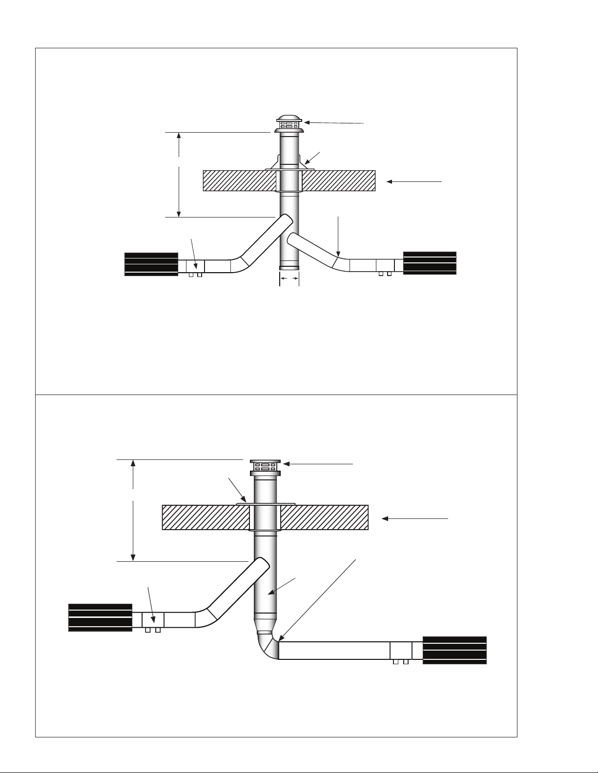
FIGURE 10: Unvented Operation
36”
36”
A
1. Ventilationequalto4CFMper1,000BTU/HRfiringratemust
beprovidedinunventedheaterinstallations
2. FordimensionsA"unvented"referto(Figure1-Minimum
ClearancestoCombustibles.)
FIGURE 10A: Single Wall
Singlewallventrun
Singlewallterminalend
FIGURE 10b: Double Wall
Doublewallventrun
Doublewallterminalend
FIGURE 11: Vertical Venting
18"(45cm)
18" (45cm) Min. 3'-0" (91cm) Min.
8"(20cm) to 10"(25cm) Max.
6' (182cm) Min.
18" (45cm) Min. 3'-0" (91cm) Min.
6' (182cm) Min.
2"(5cm) Clearance thimble
2"(5cm) Clearance thimble
required when u pipe
extends through
combustible materials
(91cm)
(91cm)
17
Operating Instructions and Owner’s ManualMr. Heater Series Heater
Outside Combustion Air Supply
TheMR.Heaterheaterisapprovedforinstallationwith
anoutsideairsupplysystem.Somecompoundssuchas
halogenatedhydrocarbonsorothercorrosivechemicalsinthe
aircanbedrawnintotheequipmentandcauseanaccelerated
rateofcorrosionofsomeoftheheatercomponents.Theuse
ofsuchchemicalcompoundsneartheenclosureshouldbe
avoided.
IMPORTANT: If the building has a slight negative
pressure or contaminants are present in the air, an
outside combustion air supply to the heaters is strongly
recommended.
Foranoutsideairsupply,afour(4”)inchO.D.singlewallpipe
maybeattachedtotheheater.Theductmaybeuptoforty-five
(30’)ft.maximumlengthortwo(2’)ft.minimumlengthwith
nomorethantwo(2)elbows.(SeeGeneralRequirementson
page15foradditionalinformation.)
Theairsupplyductmayhavetobeinsulatedtoprevent
condensationontheoutersurface.Theoutsideairterminal
shouldbesecurelyfastenedtotheoutsidewallbydrillingfour
(4)1/4”diameterholesintheoutsideflange;woodscrewsor
boltsandexpansionsleevesmaybeusedtofastenterminal.
FIGURE 13: Non-Pressurized Outside Air Supply Duct
PVCPipe,“DryerHose”,orequivalentmaybeusedinsteadof
standardventpipe.
SECTION 6
Gas Piping
Readapplicablewarningsin(Section1)beforeproceedingwith
GasPipeinstallation.Improperinstallationmayresultinproperty
damage,severeinjury,ordeath.
Meterandservicemustbelargeenoughtohandlealltheburners
beinginstalledplusanyotherconnectedload.Thegaslinewhich
feedthesystemmustbelargeenoughtosupplytherequiredgas
withamaximumpressuredropof1/2”watercolumn.Whengas
pipingisnotincludedinthelayoutdrawing,thelocalgassupplier
willusuallyhelpinplanningthegaspiping.
A1/2”tappingateachburnerlocationmustbelocatedandoriented
asshownin(Figure14).Tochecksystempressure,putaplugged
1/8”NPTtappinginthegaslineattheconnectiontotheburner
farthestfromthesupply.Beforeconnectingtheburnerstothe
supplysystem,verifythatallhighpressuretestingofthegaspiping
hasbeencompleted.Donothighpressuretestthegaspipingwith
theburnersconnected.
Followtheseinstructionstoensureaprofessionalgassupply
installation:
• Supportallgaspipingwithsuitablepipehanging
materials.
• Usewroughtironorwroughtsteelpipeandmalleable
ironfitting.Allpipefittingsshouldbenewandfree
fromdefects.Carefullyreamthepipeandtubingends
toremoveobstructionsandburrs.
• UseL.P.gas-resistantjointcompoundonallpipe
threads.
• Checkthepipeandtubingendsforleaksbefore
placingheatingequipmentintoservice.When
checkingforgasleaks,usesoapandwatersolution:
NEVER USE AN OPEN FLAME.
Installtheflexgasconnectorasshown.Theflexgasconnector
accommodatesexpansionoftheheatingsystemandallowsforeasy
installationandserviceoftheburner.
FIGURE 14: Gas Line Connection with Stainless Steel Flex Gas
Connector
Shut-OffValvemustbeparallel
toburnergasinlet.The2”
displacementshownisforthecold
condition.Thisdisplacementmay
reducewhenthesystemisfired.
Shut–offValve
12 "
2"
1/2"StainlessSteelFlexGasConnector
Stk.#16401
90°
45°
0°
45°
4" (10 cm)
Seal All Joints
4"
Heater Movement
Heater Movement
Heater Movement
Heater Movement
Outside Air
Terminal
Flex Pipe
6" (15 cm) to
12" (30 cm) Long
Flex Pipe
6" (15 cm) to
12" (30 cm) Long
Flex Pipe
6" (15 cm) to
12" (30 cm) Long
Outside Air
Terminal
NOTE:
Flue pipe requires additional
support. Flex pipe will not
support riser and outside
air terminal
Vertical Outside Air
Horizontal Outside Air
FIGURE 14A: Incorrect Gas Line Connection with Stainless
Steel Flex Gas Connector
18
Mr. Heater Series Heater Operating Instructions and Owner’s Manual
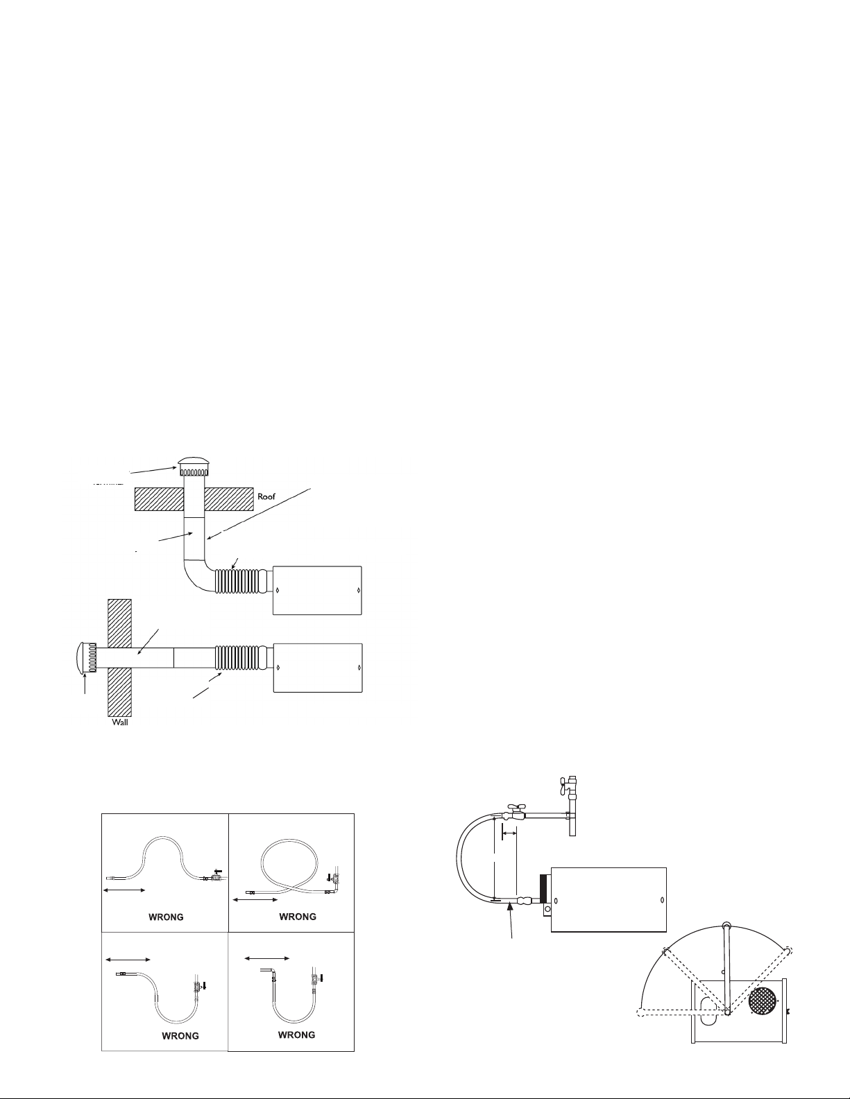
SECTION 7
Wiring
Heatersarenormallycontrolledbythermostats.Linevoltage
thermostatsarewireddirectly(seeFigure15),24Vthermostatsare
wireddirectlyusingtheterminalsonburnerbox(seeFigure16).
HeatersmustbegroundedinaccordancewiththeNationalElectric
CodeANSI/NFPA-70orcurrentCanadianElectricalCode,CSA
C22.1.Heatersmayalsobecontrolledwithamanuallinevoltage
switchortimerswitchinplaceofthethermostat.
FIGURE 15: Line Voltage Thermostat Wiring
T
H
N
120v – 60 Hz
White
White
Green
Green
Supply Circuit
120v – 60 Hz
Supply Circuit
Burners
(Maximum – 2 per Thermostat)
Burners
(Maximum – 1 per Thermostat)
Black
Black
H
N
T
FIGURE 16: Low Voltage Thermostat Wiring
T
H
N
120v – 60 Hz
White
White
Green
Green
Supply Circuit
120v – 60 Hz
Supply Circuit
Burners
(Maximum – 2 per Thermostat)
Burners
(Maximum – 1 per Thermostat)
Black
Black
H
N
T
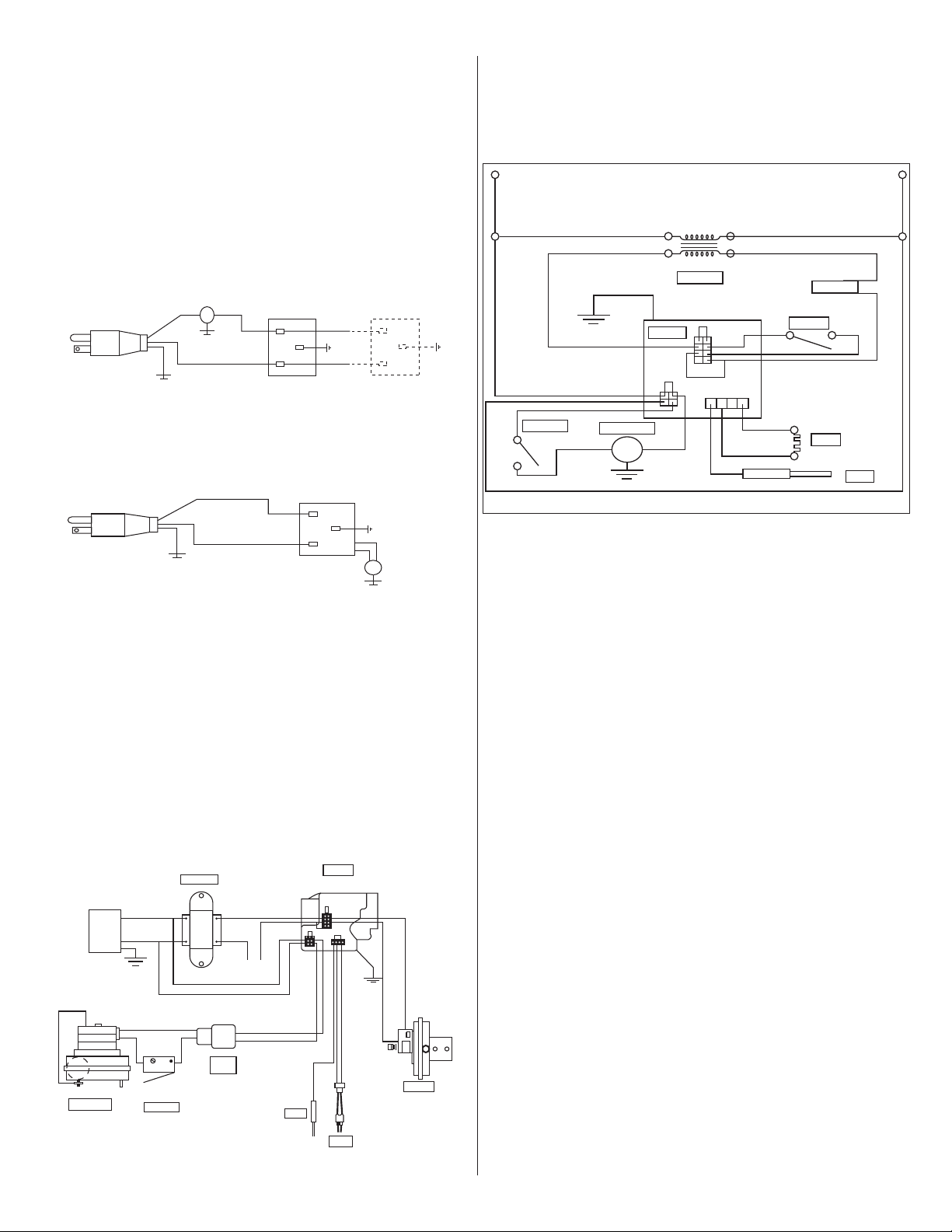
FIGURE 17: MR. Heater Burner Internal Wiring
• Ifanyoftheoriginalwireassuppliedwiththe
appliancemustbereplaced,itmustbereplacewith
wiringmaterialhavingatemperatureratingofatleast
105°Cand600volts.
• Eachburnermustbeelectricallygroundedin
accordancewiththeNationalElectricCodeANSI/NFPA
-70orcurrentCanadianElectricalCode,CSAC22.1.
FIGURE 18: MR. Heater Burner Internal Wiring Ladder Diagram
VAC
120
120V
24V
Black
Black
Purple
Yellow
Yellow
Black
Black
Black
Green
Green
Orange
Transformer
White
White
White
THERMOSTAT
White
Blue
Gas Valve
Air Switch
Ignitor
Sensor
Motor / Blower
Door Switch
Terminal
Bushing
120V
L2
(NEUTRAL)
White
White
White
White
White
White
Gray
Orange
Transfomer
Thermostat
Air Switch
Gas Valve
Door Switch
Motor / Blower
Ignitor
Sensor
Blue
Yellow
Yellow
Purple
Black
Black
Black
Black
L2 (HOT)
24V

19
Operating Instructions and Owner’s ManualMr. Heater Series Heater
9. Aqualifiedserviceagencyshouldbecontactedforservice
otherthanroutinemaintenance.
10. Checkventterminalandfreshairinlettoseethattheyhave
notbeenblockedduringthenon-heatingseason.Ifeither
pipeisrestricted,theairswitchwon’tclose,resultingina
no-heatsituation.
Troubleshooting
CAUTION:BeforeopeningtheMR.Heater
burnerdoorforanytypeofservice,besure
thegassupplyhasbeenshutoffattheheater
andtheelectricalcordfromtheburnerbox
hasbeenunplugged.
Blower Motor 1.Isthethermostatcallingforheat?Isthere
Fails to Run: 115Vattheburnerreceptacle?
2.Checkblowersidedoorforseal.Checkdoor
switch.Replaceifnecessary/
3.Checkblowerforobstructions.Replace
blowerifnecessary.
Igniter 1.Checkigniterfordamage.Replaceif
Does Not Glow: necessary.
2.Checkvoltageandresistanceatigniter.
(Voltageshouldbe115V.Resistanceshould
be40-75ohms.)
3.Checkforobstructionstotheairinletand
outlet.
4.Checkwiringandhoseconnectionstothe
airswitch.Replaceifnecessary.
5.Checkvoltagesattransformerprimaryand
secondary.Replacetransformerormoduleif
necessary.
Valve Does Not Gaspressuredownstreamofgascontrolcan
Come On: bemeasurebyusingamanometerand
connectingtopressuretaponcontrol/
1.ChecktoseeifmanualvalveheaterisON.
2.Checktoseeifmanualvalveknobonheater
gascontrolinON.
3.Supplygaspressurecanbecheckedat1/8”
NPTpressuretappingonheaterexternal
manualvalve.
4.Checktoseeifgascontrolisopening:no
manifoldpressureindicatesvalveisclosed.
Ifthevalveisclosed,eitherthegasvalveor
theignitionmoduleisfaulty.
WARNING:Donotdisconnectgroundleads
insideheater.Donotinterchangegrounded
andungroundedleadsontransformeror
ignitionmodule.
Burner Does Not 1.Checktoseeifgaslineswereproperly
Light: purgedofair.
2.Checkinletandoutletgaspressureduring
ignitionperiod.
Naturalinletpressureshouldbe4.6”
Naturaloutletpressureshouldbe3.5”
LPinletpressureshouldbe11.0”
LPoutletpressureshouldbe10.25”
3.Checkforproperorificeandairplate.
SECTION 8
Operation & Maintenance
Sequence of Operation
1. Turnthethermostatup.Whenthethermostatcallsforheat,
blowermotorwillenergize.
2. WhenthemotorapproachesnominalrunningRPM,theair
provingswitchclosesandactivatestheignitionmodule.
3. Theignitionmodulethenenergizesthehotsurfaceigniterfor
atimedwarm-upperiod(approximately45to60seconds.)
4. Afterthewarm-upperiod,thegasvalveisenergized.
5. Duringthelastpartofthesequence,theigniterisde-
energizedandisconvertedtoaflamesensingrod.
6. Ifaflameisdetected,thegasvalveremainsopen.Whenthe
callforheatissatisfied,andthesystemcontrolmechanism
de-energizestheburnerlinevoltagesupply,thegasvalvesare
turnedoff.
7. Ifnoflameisdetectedonasingle-trymodule,thegasvalve
isclosed,andthemodulewilllockoutuntilitisreset.Reset
isaccomplishedbyremovingpowerfromthemoduleforat
leastfive(5)seconds(thermostatcyclerequired.)
8. Ifnoflameisdetectedonathree-trialmodule,thegas
valveisclosed,andapurgeperiodbegins.Afterthepurge,
themoduleactstopowertheigniterforasecondwarm-
upperiod,andasecondtrialforignitionperiod.Ifflameis
stillnotestablished,athirdandfinalpurge,warm-up,and
trialcyclebegins.Afterthreetrials,themodulewilllockout
untilreset.Resetisaccomplishedbyremovingpowerfrom
themoduleforatleastfive(5)seconds(thermostatcycle
required.)
9. Onathree-trialmodule,ifflameisestablishedandlost
onthefirstorsecondtrial,thegasvalveisturnedoff,a
purge,warm-up,andtrialforignitionwilloccuronathree-
trialmodule,onlythreetrialsforignitionareallowedper
thermostatcycle.
Maintenance
Forbestperformance,thefollowingmaintenanceproceduresshould
beperformedbeforeeachheatingseason:
1. Besuregasandelectricalsupplytoheaterareoffbefore
performinganyserviceormaintenance.
2. Checkconditionofblowerscrollandmotor.Dirtanddust
maybeblownoutwithcompressedair,oravacuumcleaner
maybeused.Whenusingcompressedairdonotexceed30
psiinordertonotdamagefragilehotsurfaceigniter.
3. Checkconditionofburner.Carefullyremoveanydustor
debrisfrominsidetheburnerboxorburnercup.
4. Inspecttheigniter.Replaceigniterifthereisexcessivecarbon
residue,erosion,breakageorotherdefects.
5. Checktheinsideofthefiringtubewithaflashlight.Ifcarbon
orscalearepresent,scrapeoutthedepositswithawire
brushorrod,ormetalplateattachedtoawoodenpole.
6. Checktoseethattheburnerobservationwindowisclean
andfreeofcracksorholes.Cleanorreplaceasnecessary.
7. Checkthefluepipeforsootordirt.Aftercleaningas
necessary,re-attachthefluepipetotheheater.
8. Outsidesurfacesofheatermaybecleanedbywipingwitha
dampcloth.
20
Mr. Heater Series Heater Operating Instructions and Owner’s Manual
Burner Does Not 1.Checkgroundwirecontinuity.
Stay Lit: 2.Checkburnerinternalwiringforreversed
leads.
3.Checkinsulationontheigniterleads.
4.Replacemoduleifnecessary.
Honeywell Valve LED Status
TheMR.HeaterseriesTubeHeaterisequippedwithahoneywell
SmartValve.Thisvalvehasabuilt-indiagnosticprogram,whichwill
assistintroubleshootingintheeventofavalve-relatedproblem.The
LEDor(LightEmittingDiode)islocatedonthetopofthevalveas
shownindiagrambelow.TheLEDstatusindicationsarelistedbelow
tohelpwiththetroubleshooting.
FIGURE 19:
OFF INDICATED
Off Nopowertothecontrol
Bright-Dim Normaloperation.
Thisindicationshowswheneverthesystemis
powered,unlesssomeabnormaleventhasoccurred.
2-Flashes Airflowprovidingswitchremainsclosedlongerthan
30secondsaftercallforheatbegins(airproviding
switchstuckclosed.)
3-Flashes Airflowprovidingswitchremainsopenlongerthan30
secondsaftercombustionairblowerisenergized-or
blowerdoesnotenergize.
4-Flashes Whitejumperwireisloose.
5-Flashes Flamesignalsensedoutofpropersequence.
6-Flashes SystemLockout.
LED
HoneywellSmartValve

21
Operating Instructions and Owner’s ManualMr. Heater Series Heater
SECTION 9: Troubleshooting Guide. Mr. Heater
START
Turnonthermostat
Doesblowerturn
on?
Yes
Doestheigniter
warmupandglow
red?
Yes
No
CheckThermostat
andWiring.Isthe
powersupplytounit
115V?
No
Findthesource
oftheelectrical
problem
CheckLEDindicatoronSmartValvefor
indicationoffault.RefertoSmartValvetesting
onpage20todetermineproblem.
No
Istheairintakeor
exhaustblocked?
Yes
RemoveObstruction
Checkwiringand
connections
No
Istheignitor
damaged?
No
Checkvoltageat
ignitor.Isit115V
duringignition
cycle?
Yes
Isblowersidedoor
inplace?
No
Replacedoor
No
Checkwiringand
hoseconnectionto
airswitch.Arethey
OK?
Yes
Isthevoltageat
thetransformer
secondary24V?
No
Isthevoltageatthe
transformerprimary
115 V
Replaceignitor.
Yes
No
Istheresistance
throughigniter40
to75ohms?
Removedoor.Is
voltageatdoor
switch115V?
Yes
No
Checkvoltageat
gasvalve.
Checkfor115VtransformerinputatplugC3
onSmartValve.Checkfor115Voutputof
C3.Ifnooutputvoltageispresentreplace
SmartValve.
Replacewiringand/
orhoseconnection.
No
Jumperwiresat
pressureswitch.
Doestheignitor
glowred?
Yes
ReplacetransformerYes
Checkwire
connections.
Yes
Depressswitch.
Doesblowercome
on?
Yes
Yes
No
Checkvoltageto
motor.Isit115V?
Yes
Istheblowerfan
obstructed?
No
Replaceblower
motor.
Replacepressure
switch.
Yes
ReplaceSmartValve.
No
CheckLEDindicatoronSmartValvefor
indicationoffault.RefertoSmartValvetesting
onpage21todetermineproblem.
Checkdoorfit.If
damaged,replace
door.
Replaceswitch.
No
Removeobstruction
Yes
Afterignitorwarm-
upperiod,doesthe
valveclick?
Yes
Doestheburner
light?
Yes
Doestheburner
stayon?
Yes
Doestheburner
rununtilthecall
forheatends?
Ifaproblemstillexists,contactMr.Heater,IncTechnicalProductsCustomer
Service1-866-447-2194
No
TheSmartValvechecksthestatusoftheblowerprovingswitchcontactsmustseeachangeinthe
contactwitheveryfiringcycle.Placingajumperattheswitchoutofsequencewillresultinafaultwith
theLEDindicatorflashingtwotimes.
Werethegaslinespurgedofair?
No
No
Yes
Checkinletgaspressure.Ispressurecorrect?
Refertopage40forcorrectpressureforunit.
Yes
Checkinletgasshutoff.Adjustregulator.
Contactgassupplier
Isthecontinuityof
thegroundwire
OK?
No
Theswitchonthegasvalvemustbeintheon
positionandthelinepurgedofair.
No
Repairwiring.
No
Checkthecontinuityofthegroundwire.
Checkthethermostat.
Checkoutletgaspressureduringignitioncycle.
Isthepressure3.5”w.c.fornaturalor10.5”
w.c.forlp?
Yes
Adjusttoproperpressure.
No
AreL1andL2
reversed?
Yes
Yes
Repairwiring
Isthewiringatthe
SmartValveOK?
No
Repairwiring
Istheinsulationon
thesensorleadOK?
No
Repairwiring
No
Yes
Yes
Arethewiresto
theSmartValveOK?
Yes
ReplaceSmartValve
No
Replace/repairwires.
Yes
Checkforproper
burnerorificeand
airplate.
Isthesensor
positioned
properly?
Yes
Isthesensordirty?
No
ReplaceSensor
No
Repair/Replace
Yes
Cleansensor.
Afaultindicationofsixflashesmayindicate
thattheflamesensingcircuitisnotfunctioning
properly.Performthefollowingseriesofchecks
tocorrecttheproblem.
No
22
Mr. Heater Series Heater Operating Instructions and Owner’s Manual
Parts List for MR. Heater Tube Heaters
60,000 BTU
80,000 BTU
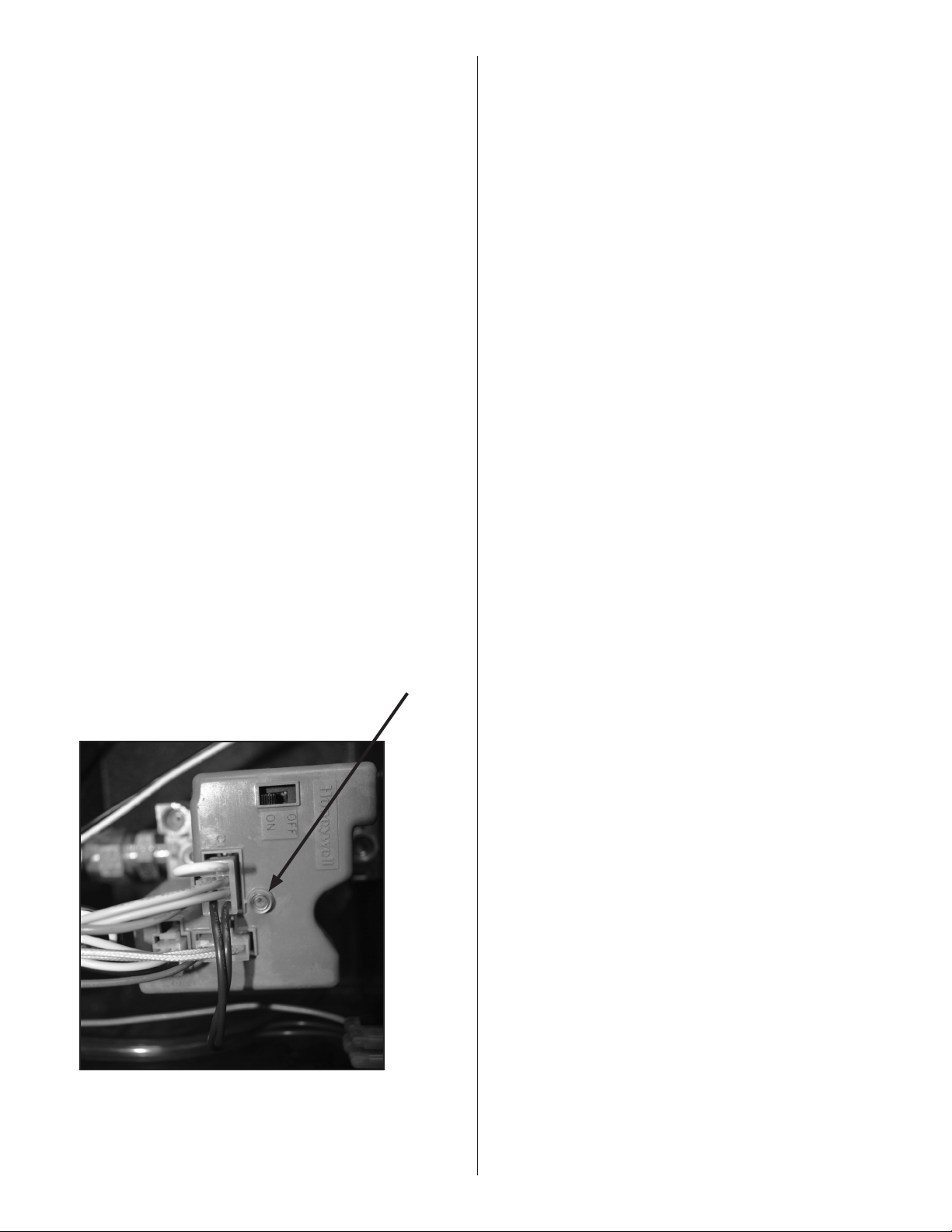
Item Stock # Description QTY Item Stock# Description QTY
1 F102650XL 60,000BTUNG/BRN&ContBox 1 1 F102652XL 80,000BTULP/BRNCONTBox 1
F102651XL 60,000BTULP/BRN&ContBox 1 F102653XL 80,000BTUNG/BRNCONTBox 1
2 F106404XL TubeSet-20' 1 2 F106404XL TubeSet-20' 1
06413 TubeH.E.4"O.D.X10' 2 06413 TubeH.E.4"O.D.X10' 2
3 00418A Reflector 2 3 00418A Reflector 2
4 03445 TurbulatorBaffle10' 1 4 03445 TurbulatorBaffle10' 1
5 14585P Hanger 4 5 14585P Hanger 4
6 02753 FrontFlange 6 02753 FrontFlange
7 14612 TubeCoupling 1 7 14 612 TubeCoupling 1
8 14616 KeyforTubeCoupling 1 8 14 616 KeyforTubeCoupling 1
9 00 419 ReflectorEndCap 2 9 00 419 ReflectorEndCap 2
10 09369 SpringClips 8 10 09369 SpringClips 8
10
9
3
4
5
7
2
6
1
8
40,000 BTU
Item Stock # Description QTY Item Stock# Description QTY
1 F102594XL 40,000BTUNG/BRN&ContBox 1 4 03445 TurbulatorBaffle9' 1
1 F102595XL 40,000BTULP/BRN&ContBox 1 5 14585P Hanger 4
2 F106408XL TubeSet-10' 1 6 02753 FrontFlange 1
06413 TubeH.E.4"O.D.X10' 2 7 00 419 ReflectorEndCap 2
3 00418A Reflector 2 8 09369 SpringClips 8
1
2
3
6
5
8
4
7
23
Operating Instructions and Owner’s ManualMr. Heater Series Heater
1
6
2
7
8
4
10
9
3
5
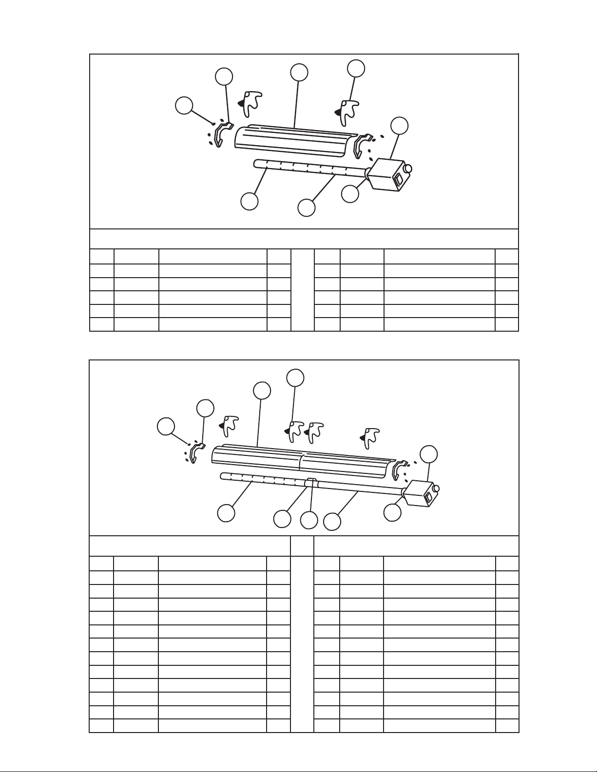
80,000 BTU
Item Stock # Description QTY Item Stock# Description QTY
1 F102652XL 80,000BTUNG/BRN&ContBox 1 6 02753 FrontFlange 1
F102653XL 80,000BTULP/BRN&ContBox 1 7 14 612 TubeCoupling 2
2 F106405XL 80,000BTU,/TubeSet-30' 1 8 14 616 KeyforTubeCoupling 2
06413 TubeH.E.4"O.D.X10' 3 9 00 419 ReflectorEndCap 2
3 00418A Reflector 3 10 09369 SpringClips 8
4 03445 TurbulatorBaffle10' 1
5 14585P Hanger 6
1
6
2
7
8
4
10
9
3
5
100,000 BTU
Item Stock # Description QTY Item Stock# Description QTY
1 F102654XL 100,000BTUNG/BRN&ContBox 1 6 02753 FrontFlange 1
F102655XL 100,000BTULP/BRN&ContBox 1 7 14 612 TubeCoupling 2
2 F106401XL TubeSet-30' 1 8 14 616 KeyforTubeCoupling 2
06413 TubeH.E.4"O.D.X10' 3 9 0 0 419 ReflectorEndCap 2
3 00418A Reflector 3 10 09369 SpringClips 8
4 03447 TurbulatorBaffle5' 1
5 14585P Hanger 4
24
Mr. Heater Series Heater Operating Instructions and Owner’s Manual
100,000 BTU
125,000 BTU
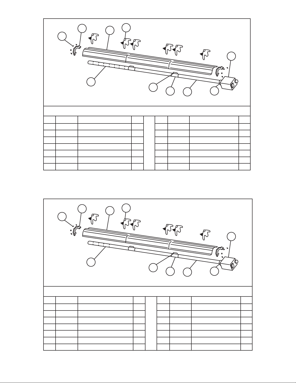
Item Stock # Description QTY Item Stock# Description QTY
1 F102654XL 100,000BTUNG/BRN&ContBox 1 1 F102656XL 125,000BTUNG/BRN&ContBox 1
F102655XL 100,000BTULP/BRN&ContBox 1 F102657XL 125,000BTULP/BRN&ContBox 1
2 F106406XL TubeSet-40' 1 2 F106406XL TubeSet-40' 1
06413 TubeH.E.4"O.D.X10' 4 06413 TubeH.E.4"O.D.X10' 4
6 02753 FrontFlange 1 3 02753 FrontFlange 1
4 14612 TubeCoupling 1 4 14 612 TubeCoupling 1
5 14616 KeyforTubeCoupling 1 5 14 616 KeyforTubeCoupling 1
6 00418A Reflector 4 6 00418A Reflector 4
7 14585P Hanger 8 7 14585P Hanger 8
8 00 419 ReflectorEndCap 2 8 00 419 ReflectorEndCap 2
9 09369 SpringClips 8 9 09369 SpringClips 8
8
9
6
7
1
3
2
4
5
125,000 BTU / 150,00 BTU / 175,000 BTU
Item Stock # Description QTY Item Stock# Description QTY
1 F102656XL 125,000BTUNG/BRN&ContBox 1 3 02753 FrontCasting 1
1 F102657XL 125,000BTULP/BRN&ContBox 1 4 14 612 TubeFlange 2
1 F102658XL 150,000BTUNG/BRN&ContBox 1 5 14616 KeyforTubeCoupling 2
1 F102659XL 150,000BTULP/BRN&ContBox 1 6 00418A Reflector 5
1 F102660XL 175,000BTUNG/BRN&ContBox 1 7 14585 Hanger 10
1 F102661XL 175,000BTULP/BRN&ContBox 1 8 00 419 ReflectorEndCap 2
2 F106407XL TubeSet-50' 1 9 09369 SpringClips 8
06413 TubeH.E.4"O.D.X10' 3
1
3
2
7
5
4
6
9
8
25
Operating Instructions and Owner’s ManualMr. Heater Series Heater
1
2
3
7
6
4
5
9
8
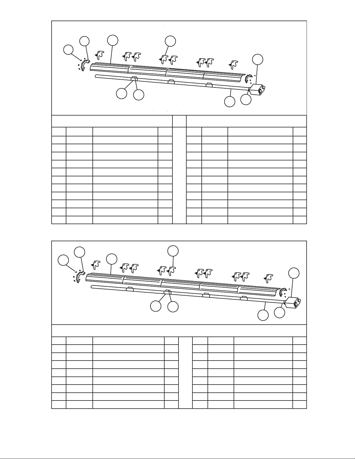
150,000 BTU 175,000 BTU
Item Stock # Description QTY Item Stock# Description QTY
1 F102658XL 150,000BTUNG/BRN&ContBox 1 1 F102660XL 175,000BTUNG/BRN&ContBox 1
1 F102659XL 150,000BTULP/BRN&ContBox 1 1 F102661XL 175,000BTULP/BRN&ContBox 1
2 F106403XL TubeSet-60' 1 2 F106403XL TubeSet-60' 1
06413 TubeH.E.4"O.D.X10' 6 06413 TubeH.E.4"O.D.X10' 6
3 02753 FrontFlange 1 3 02753 FrontFlange 1
4 14 612 TubeCoupling 5 4 14 612 TubeCoupling 5
5 14 616 KeyforTubeCoupling 5 5 14616 KeyforTubeCoupling 5
6 00418A Reflector 6 6 00418A Reflector 6
7 14585P Hanger 12 7 14585P Hanger 12
8 0 0 419 ReflectorEndCap 2 8 0 0 419 ReflectorEndCap 2
9 09369 SpringClips 8 9 09369 SpringClips 8
Stock Number Description
10371................................... Thermostat24volt
10392................................... Thermostat110Volt
17370................................... ChainKit
16401.................................. 24”StainlessSteelFlexible
16405.................................. 1/2"x24"3/4"StainlessSteel
F106414............................... 180°U-TubeAccessoryKit
F106415............................... 90°ElbowAccessoryKit
19021 ................................... VentAdaptor
06430.................................. VentCap
00438.................................. SideReflectorkit
01376 ................................... Deflectorkit(5')
19031 ................................... Turnbuckle5/16"-18"
INSTALLATION KITS
F111751…………Installationkitfor20’tubeheater
F111752…………Installationkitfor30’tubeheater
F111753…………Installationkitfor40’tubeheater
F111754…………Installationkitfor50’tubeheater
F111755…………Installationkitfor60’tubeheater
Installationkitincludes:
24-voltthermostat,ventcap,24”stainlesssteelflexiblegas
connector,gasshutoffvalve,andchainkitsrequiredtohangheater.
CONVERSION KITS
60,000 BTU
11732 LPTONG 117 33 NGTOLP
80,000 BTU
1173 4 LPTONG 117 3 5 NGTOLP
100,000 BTU
1173 6 LPTONG 117 37 NGTOLP
125,000 BTU
1173 8 LPTONG 117 3 9 NGTOLP
150,000 BTU
1174 0 LPTONG 11741 NGTOLP
175,000 BTU
1173 0 LPTONG 117 31 NGTOLP
ACCESSORY PARTS LIST

26
Mr. Heater Series Heater Operating Instructions and Owner’s Manual
1
2
3
6
5
4
ITEM# EGI # DESCRIPTION QTY
18 05501XL 100KAIRPLATE 1
19 05500XL 125KAIRPLATE 1
20 05503XL 150KAIRPLATE 1
21 05508XL 175KAIRPLATE 1
22A 00016 HONEYWELLSMARTVALVE(NG) 1
22B 00017 HONEYWELLSMARTVALVE(LP) 1
23 02758 GASVALVEOUTLETFITTING 1
24 17379 GASMANIFOLD 1
25 02720 ORIFICEHOLDERFITTING 1
26 98541 ORIFICEHOLDERFLATWASHER 1
27 05794 40KORIFICE(NG) 1
28 05749 40KORIFICE(LP) 1
29 05726 60KORIFICE(NG) 1
30 05744 60KORIFICE(LP) 1
31 05718 80KORIFICE(NG) 1
32 05737 80KORIFICE(LP) 1
33 0 5712 100KORIFICE(NG) 1
ITEM# EGI # DESCRIPTION QTY
34 05733 100KORIFICE(LP) 1
35 05703 125KORIFICE(NG) 1
36 05730 125KORIFICE(LP) 1
37 05796 150KORIFICE(NG) 1
38 05728 150KORIFICE(LP) 1
39 05799 175ORIFICE(NG) 1
40 05725 175KORIFICE(LP) 1
41 98547 EXTERNALTOOTHWASHER 1
42 02371 BURNERCUP 1
43 10391A DOORSWITCH 1
44 02721 BLOWER2-TERMINALBUSHING 1
45 07376 MOTOR 1
46 12395 BLOWERGASKET 1
47 02718 BLOWERSCREEN 1
48 02795 SIGHTWINDOW 1
ITEM# EGI # DESCRIPTION QTY
1 02716XL ENCLOSURE 1
2 02725XL CONTROLSIDECOVER 1
3 02749XL MOTORSIDECOVER 1
4 12397 FRONTFLANGEGASKET 1
5 02753 FRONTTUBEFLANGE 1
6 08364A TRANSFORMER 1
7 02836 40KPRESSURESWITCH 1
8 10 413 A 60-125KPRESSURESWITCH 1
9 10 414A 150K-175KPRESSURESWITCH 1
10 02730 FLAMESENSORROD 1
11 02765 HOTSURFACEIGNITER 1
12 02847 THERMOSTAT3TERMINALBUSHING 1
13 99101 ELECTRICALJUNCTIONBOX 1
14 02747 BLOWERINTAKEFLANGE 1
15 05510XL 40KAIRPLATE 1
16 06606XL 60KAIRPLATE 1
17 05502XL 80KAIRPLATE 1
40
41
42
43
44
45 46
47
48
7-9
10
11
12
13
14
15-
21
22
23
24
25
26
27-

27
Operating Instructions and Owner’s ManualMr. Heater Series Heater
NOTES:

28
Mr. Heater Series Heater Operating Instructions and Owner’s Manual
WARNING:
USEONLYMANUFACTURER’SREPLACEMENTPARTS.USEOFANYOTHERPARTS
COULDCAUSEINJURYORDEATH.REPLACEMENTPARTSAREONLYAVAILABLE
DIRECTFROMTHEFACTORYANDMUSTBEINSTALLEDBYAQUALIFIEDSERVICE
AGENCY.
FOR INFORMATION REGARDING SERVICE OR PARTS:
Contactyourlocalheatingservicetechnicianordealer.
FOR ADDITIONAL INFORMATION:
PleasecallToll-Free866-447-2194—www.Mr.Heaterbyenerco.com
Ourofficehoursare8:00AM—5:00PM,EST,MondaythroughFriday.
Pleasehavethemodelnumber,serialnumberanddateofpurchaseready.
LIMITED WARRANTY
Thecompanywarrantsthisproducttobefreefromimperfectionsinmaterialor
workmanship,undernormalandproperuseinaccordancewithinstructionsoftheMr.Heater
Company,foraperiodof10yearsfromthedateofdeliverytothebuyerwiththefollowing
exceptions.
•Forinstallationinacarwashandinareaswithexposuretocorrosivechemicals,suchas
ammonia,chlorine,etc.,thewarrantywillbelimitedto2yearsontubesand1yearonall
othercomponents.
TheMr.HeaterCompany,atitsoption,willrepairorreplaceproductsreturnedbythebuyer
tothefactory,transportationprepaidwithinsaidwarrantyperiodandfoundbytheMr.
HeaterCompanytohaveimperfectionsinmaterialorworkmanship.
Ifapartisdamagedormissing,callourCustomerServiceDepartmentat866-447-2194.
AddressanyWarrantyClaimstotheCustomerServiceDepartment,Mr.Heater,Inc,4560W.
160THST.,CLEVELAND,OHIO44135.Includeyourname,addressandtelephonenumberand
includedetailsconcerningtheclaim.Also,supplyuswiththepurchasedateandthename
andaddressofthedealerfromwhomyoupurchasedourproduct.
TheforegoingisthefullextentoftheresponsibilityoftheMr.HeaterCompany.Thereareno
otherwarranties,expressorimplied.Specificallythereisnowarrantyoffitnessforaparticular
purposeandthereisnowarrantyofmerchantability.InnoeventshalltheCompanybeliable
fordelaycausedbyimperfections,forconsequentialdamages,orforanychargesofthe
expenseofanynatureincurredwithoutitswrittenconsent.Thecostofrepairorreplacement
shallbetheexclusiveremedyforanybreachofwarranty.Thereisnowarrantyagainst
infringementofthelikeandnoimpliedwarrantyarisingfromcourseofdealingorusageof
trade.Thiswarrantywillnotapplytoanyproductwhichhasbeenrepairedoralteredoutside
ofthefactoryinanyrespectwhichinourjudgmentaffectsitsconditionoroperation.
Somestatesdonotallowtheexclusionorlimitationofincidentalorconsequentialdamages,
sotheabovelimitationorexclusionmaynotapplytoyou.ThisWarrantygivesyouspecific
legalrights,andyoumayhaveotherrightswhichvaryfromstatetostate.
Mr.Heater,Inc,4560W.160THST.,CLEVELAND,OHIO44135•866-447-2194
©2016,Mr.Heater,IncAllrightsreserved
Mr.Heater,Increservestherighttomakechangesatanytime,withoutnoticeor
obligation,incolors,specifications,accessories,materialsandmodels.
OPERATING INSTRUCTIONS AND OWNER’S MANUAL
110VMODELS
ANSI Z83.20b-2011 CSA 2.34b-2011
C
US
40,000BTU 60,000BTU
80,000BTU 100,000BTU
125,000BTU 150,000BTU
175,000BTU
— QUOIFAIRESIVOUSSENTEZDUGAZ
• Ouvrezlesfenêtres
• N’ESSAYEZ PAS d’allumerquelqueappareilquecesoit.
• NE BASCULEZ PAS lesinterrupteursélectriques.
• N'UTILISEZ PAS lestéléphonedansl'édifice.Appelezimmédiatementvotrefournisseurdegazlocalàpartirdu
téléphoned'unvoisin.Suivezlesinstructionsdufournisseurdegaz.
• Ne touchez àaucuncommutateurélectrique;n'utilisezaucuntéléphonedansvotrebâtiment.
•
L'installationetl'entretiendoiventêtreréalisésparuninstallateurqualifié,uneentreprised'entretienouunfournisseurdegaz.
• Sivousnepouvezpasrejoindrevotrefournisseurdegaz,appelezleservicedesincendies.
POUR VOTRE SÉCURITÉ :
N’entreposezetn’utilisezpasd’essenceoud’autresliquidesouvapeursinflammablesàproximitédecetype
d’appareiloudetoutautreappareil.
AVERTISSEMENT : Sil'informationdanscesinstructionsn'estpassuivieexactement,unincendieouuneexplosion
pourraitseproduirecausantdesdommagesauxbiens,desblessurespersonnellesouundécès.
2016CB
Mr.Heater,Inc.,4560W.160THST.,CLEVELAND,OHIO44135•866-447-2194
AVERTISSEMENT: Une installation, un réglage, une modification, une réparation ou un
entretien incorrect peut entraîner des dommages matériels, des blessures ou la mort. Lisez
attentivement les instructions d'installation, de fonctionnement et d'entretien avant de procéder a
l'installation ou a l'entretien de cet équipement.
INSTRUCTIONS D'UTILISATION
ET MANUEL DU PROPRIÉTAIRE
VEUILLEZ LIRE ATTENTIVEMENT LES INSTRUCTIONS :Lireetobservertoutesles
instructions.Conservercesinstructionsdansunendroitsécuritairepourvousyréférer
ultérieurement.Interdisezàquiconquen’ayantpaslulesprésentesinstructionsd'assembler,
d'allumer,derégleroudefairefonctionnercettefournaise.
Nodemodèle
LANGUES INCLUSES
• ANGLAIS
• FRANÇAIS
• ESPAGNOL
MR. Heater Fournaises à infrarouge de
faible intensité alimentées au gaz et approuvées pour
applications commerciales
40,000BTU60,000BTU
80,000BTU100,000BTU
125,000BTU150,000BTU
175,000BTU
2
Mr. Heater Series Chauffe-
INSTRUCTIONS D'UTILISATION ET MANUEL DU PROPRIÉTAIRE
SECTION 1 : Présentation
LesmodèlesMr.Heatersontdesfournaiseséconomiques,
àinfrarougefacilementassembléessurleterrainetqui
demandentseulementunentretienminime.Ellessontconçues
pourfournirdesannéesd'utilisationéconomiqueetdeservice
exemptdeproblèmes.
Vérification de l'expédition
Vérifiezl'expéditionparrapportauconnaissementpourtoute
piècemanquante.Deplus,vérifiezpourtoutdommageexterne
auxboîtes.Preneznotedetoutepiècemanquante,oude
toutdommageexterneauxboîtes,surleconnaissementen
présenceduconducteurducamiondelivraison.Leconducteur
ducamiondelivraisondoitreconnaîtretoutepiècemanquante
outoutdommageenposantsesinitialessurceconnaissement
«annoté».Signalezimmédiatementtouteréclamationpourdu
matérielendommagéoudespiècesmanquantesquin'étaient
pasévidentsaumomentdel'expédition,autransporteuretà
votrereprésentantd'usineMr.Heater,Inc.
Responsabilité de l'installateur
Touteslesfournaisesetlesconduitesdegazassociéesdoivent
êtreinstalléesselonlesspécificationsapplicablesetcette
installationdoitêtreeffectuéeselonpardesentreprises(oudes
individus)trèsqualifiésdanscetypedetravail.Consultezles
inspecteurslocauxdesbâtiments,leservicedesincendiesou
votrereprésentantlocald'usineMr.Heater,Incpourdel'aide.
LesfournaisesMr.Heatersontinstalléessurlabasede
l'informationfourniedansundessindeladispositiondes
lieux,quiensembleaveclescodesetréglementationscités,
sontl'informationdebaserequisepourterminerl'installation.
L'installateurdoitfournirtoutlematérielrequisquin'est
pasfourniscommeéquipementstandard,etilenestdesa
responsabilitédes'assurerqu'untelmatériel,ainsiqueles
méthodesd'installationutiliséeslorsd'uneinstallation,sont
professionnelsetselontouslescodesenvigueur.
Lesreprésentantsd'usineMr.Heater,Incontreçuuneformation
etontl'expériencedansl'installationdecetéquipement
etpeuventêtreappeléspourdessuggestionsconcernant
l'installation,cequipeutéconomiserdumatérieletdel'argent.
AVERTISSEMENT :
DANGERD'INCENDIE,D'INHALATIONETD'EXPLOSION.
GARDEZLESCOMBUSTIBLESSOLIDESTELSQUELESMATÉ-
RIAUXDECONSTRUCTIONLEPAPIERETLECARTONÀUNE
DISTANCESÉCURITAIREDEL'APPAREILDECHAUFFAGETEL
QUERECOMMANDÉDANSLESINSTRUCTIONS.N'UTILISEZ
JAMAISLAFOURNAISEDANSUNENDROITQUICONTIENT
OURISQUEDECONTENIRDESCOMBUSTIBLESVOLATILES
OUENSUSPENSIONDANSL'AIR,OUDESPRODUITSTELS
QUEDEL'ESSENCE,DESSOLVANTS,DUDILUANTÀ
PEINTURE,DESPARTICULESDEPOUSSIÈREOUDES
PRODUITSCHIMIQUESINCONNUS.
AVERTISSEMENT GÉNÉRAL DE DANGER :
LENON-RESPECTDESMESURESDEPRÉVENTIONETDES
INSTRUCTIONSFOURNIESAVECCETAPPAREILDE
CHAUFFAGERISQUEDECAUSERLAMORT,DESBLESSURES
GRAVESETDESDOMMAGESOUDESPERTESMATÉRIELLES
RÉSULTANTD'INCENDIE,D'EXPLOSION,DEBRÛLURE,
D'ASPHYXIE,D'INTOXICATIONAUMONOXYDEDECARBONE
ET/OUD'ÉLECTROCUTION.
SEULESLESPERSONNESAPTESÀCOMPRENDREETÀ
RESPECTERLESINSTRUCTIONSDEVRAIENTUTILISEROUEF-
FECTUERLESERVICEDECETAPPAREILDECHAUFFAGE.
SIVOUSAVEZBESOIND'AIDEOUD'INFORMATION
CONCERNANTLAFOURNAISETELSQUEMANUEL
D'INSTRUCTIONS,ÉTIQUETTES,ETC.,VEUILLEZ
COMMUNIQUERAVECLEFABRICANT.
AVERTISSEMENT :
VOTRESÉCURITÉESTIMPORTANTEPOURVOUSETPOURLES
AUTRES,PARCONSÉQUENTVEUILLEZLIRECESDIRECTIVES
AVANTDEFAIREFONCTIONNERCETAPPAREILDECHAUF-
FAGE.
CONTENU
Section1PRÉSENTATION ........................................................2
Section2PLANIFICATION........................................................3
Section3INSTALLATIONETASSEMBLAGE..............................6
Section4SPÉCIFICATIONSD'INGÉNIERIE...............................12
Section5AÉRATION/CONDUITE……………………………………13
Section6CONDUITEDEGAZ................................................17
Section7CÂBLAGE..............................................................18
Section8ENTRETIENDUFONCTIONNEMENT......................19
Section8DÉPANNAGE.........................................................21
Section9PIÈCESDERECHANGE...........................................22
INFORMATIONSURLAGARANTIE.........................................24
AVERTISSEMENT :
L'État de la Californie exige que l'avertissement suivant
soit fourni :
LESSOUS-PRODUITSDECOMBUSTIONÉMISLORSDEL'UTILI-
SATIONDECETAPPAREILCONTIENNENTDUMONOXYDEDE
CARBONE,UNPRODUITCHIMIQUERECONNUPARL'ÉTATDE
CALIFORNIECOMMEPOUVANTCAUSERLECANCERETDES
MALFORMATIONSCONGÉNITALES(OUAUTRESDOMMAGES
AUSYSTÈMEREPRODUCTEUR).

3
INSTRUCTIONS D'UTILISATION ET MANUEL DU PROPRIÉTAIRE
Mr. Heater Series Chauffe-
SECTION 2 : Planification
Lescodesetinstructionssuivantsdoiventêtresuivislorsdela
planificationdel'installationdelafournaiseMr.Heater.Enplusde
cesinstructions,lesavertissementsàla(Section1)doiventêtre
soigneusementsuivispuisqu'uneinstallationincorrectepeutmener
àdesdommagesauxbiens,desblessuresoumêmelamort.
Normes nationales et codes applicables
Codes du gaz :
Letypedegazapparaissantsurlaplaqued'identificationdoit
êtreletypedegazutilisé.L'installationdoitêtreconformeavec
lescodeslocauxetlesrecommandationsdel'entrepriselocalede
gaz,ainsiqu'aveclecodenationaldugaz
combustible,ANSIZ223.1,dernièrerévision,(mêmequeleNFPA
bulletin54),oulecoded'installationdupropaneetdugaz
naturel,CSAB149.1.
•L'espacelibreentrelafournaiseetsonéventetlematériel
combustibleprès(quifaitpartiedubâtimentoudesonconte-
nu)doiventêtremaintenusconformesselonlanormepour
l'installationdesappareilsaugazetdesconduitesdegaz,
NFPA-54/ANSIZ223.1,dernièrerévision,codenationaldugaz
combustibleoucoded'installationdugaznatureletdupropane,
CSAB149.1.
Hangars d'aéronefs :
L'installationdansdeshangarsd'aéronefsdoitêtreen
conformitéaveclanormepourleshangarsd'aéronefs,ANSI/
NFPA-409,dernièrerévision.
•
Lesfournaisesdansleszonesd'entretienoud'entreposage
d'aéronefsdoiventêtreinstalléesàunehauteurde3m(10pi)au-
dessusdelasurfacedesailesoudesbâtisdumoteurdel'aéronef
leplusélevépouvantêtreabritédanslehangar.(Celadoitêtre
mesurédubasdelafournaisejusqu'àl'aileoulebâtidumoteur,
selonlapartielaplusélevéeàpartirduplancher).
•Danslesautressectionsdeshangarsd'aéronefs,commeles
boutiquesoulesbureaux,lesfournaisesnedoiventpasêtre
installéesàmoinsde2,4m(8pi)au-dessusduplancher.
•Lesfournaisesinstalléesdansleshangarsd'aéronefsdoivent
êtreplacéesdefaçonànepassubirdedommagesparles
aéronefs,lesgrues,leséchafaudagesmobilesoulesautres
objets.
Garages publics :
Lesinstallationsdanslesgaragesdoitêtreeffectuéesselon
lanormepourlesstructuresdestationnement,NFPA-88A,
dernièrerévisionoulanormepourlesgaragesderéparation,
NFPA-88B,dernièrerévision.
•
Lesfournaisesnedoiventpasêtreinstalléesàmoinsde2,4m
(8pi)duplancher.L'espacelibreminimumdescombustibles
doitêtremaintenudesvéhiculesstationnéssouslafournaise.
•Lorsquelesfournaisessontinstallésau-dessusd'appareilsde
levage,unespacelibreminiumdescombustiblesdoitêtre
maintenudelapartielaplusélevéedel'appareildelevage.
Aération :
L'aérationdoitêtreinstalléeselonladernièrerévisiond'ANSI
Z223.1ouCSA149.1.L'informationpartielleconcernantce
codeestfourniedans(Section5)decemanueld'installation
aveclagrandeuretlesconfigurationspourlesdispositions
d'aération.
•Toutepartiedelaconduitedefuméespassantàtraversun
murcombustibledoitêtreisoléeendoubleouavoirunebague
approuvée.Consultezladernièrerévisiond'ANSIZ223.1ou
CSA149.1.
Emplacements dangereux :
Làoùilestpossibled'avoiruneexpositionàdesvapeursou
desmatériauxaérienscombustibles,consultezleservicedes
incendieslocal,lacompagnied'assurance-incendieoules
autresautoritéspourl'approbationdel'installationproposée.
Considérations critiques
Ener-RadiantER2STGestunefournaisesuspendue.Ainsi,sa
stabilité,flexibilitéetsécuritésonttrèsimportantes.Avantde
commencerl'installation,assurez-vousquelesystèmerépond
auxexigencessuivantes.
•Conservezdesespaceslibresminimumdescombustibles,
etunedistancesécuritairedetoutmatériau,équipementet
stationdetravailsensiblesàlachaleur.
•Lesespaceslibresindiquésverslescombustiblesreprésentent
unetempératuredesurfacece30°C(90°F)au-dessusdela
températuredelapièce.Lesmatériauxdeconstructionavec
unefaibletoléranceàlachaleur(commeleplastique,lespa-
rementsdevinyle,lestoiles,etc.)peuventêtresujetsàdela
dégradationauxtempératureslesplusbasses.Ilenestdela
responsabilitédel'installateurdes'assurerquelesmatériaux
adjacentssontprotégésdeladégradation.
•
Offrirunesuspensionaveclalongueurverticaled'unechaîne
oud'unetigederotationquipossèdeaumoins5,1cm(2po)
dedéplacementhorizontalpourchaquebrûleurencoursedroi-
te.Assurez-vousquelesystèmedesuspensionestassezflexible
pouraccommoderl'expansionthermiquequiseproduitalors
quelesystèmeseréchauffe(voirlaFig.6àlapage11).
•Offrirunaccèsauxbrûleurspourl'entretien,depréférence
surlesdeuxcôtés,au-dessusetderrièrelebrûleurpourle
retrait.
•Offrirunespacelibreminimumde45,7cm(18po)entreles
brûleursetlesmursdeconstruction.(Respecteztoujoursles
espaceslibresminimumverslescombustibles).
•S'assurerquelebrûleurpossèdeunepentedescendantede
1,2cm(0,5po)paréloignementde6,1m(20pi)dubrûleur.
•Poserdesavisdansleszonesd'entreposagepourspécifierla
hauteurd'empilementmaximalpourconserverlesespaces
libresrequisverslescombustibles.
•Planifierlesoutiensurleslieux(voirlaFig.2A-Dàlapage8).
Trouvezunsoutienprèsdetouslescoudes.
•L'installationdoitseconformeraveclescodeslocauxde
construction,ouenl'absencedetelscodes,aveclecodena-
tionaldugazcombustible,ANSIZ223.1/NFPA54oulecode
d'installationdupropaneetdugaznaturel,CSAB149.1.
•Siunesourceélectriqueexterneestutilisée,lafournaise,lor-
squ'installée,doitêtreélectriquementmiseàlaterreselonle
codenationaldel'électricité,ANSI/NFPA70oul'actuelcode
canadiendel'électricité,CSAC22.1.
4
Mr. Heater Series Chauffe-
INSTRUCTIONS D'UTILISATION ET MANUEL DU PROPRIÉTAIRE
AVERTISSEMENT :
RISQUES D'EXPLOSION ET D'INCENDIE
PEUT PROVOQUER DES DOMMAGES AUX BIENS, DES BLESSURES GRAVES OU MÊME LA MORT.
Danstouslescas,lesespaceslibresauxcombustiblesdoiventêtremaintenusOmettrederespecterlesespaceslibresauxcombustiblespeut
entraînerdesdommagesauxbiens,desblessuresgravesetmêmelamort.
Lesespaceslibresminimumdoiventêtremaintenusdesvéhiculesstationnéssouslafournaise.Desavisdoiventêtreplacésdansleszones
d'entreposagepourspécifierlahauteurd'empilementmaximalpourconserverlesespaceslibresrequisverslescombustibles.
Ondoitêtreprudentlorsdel'utilisationdusystèmeprèsdematériauxcombustiblescommelebois,lepapier,lecaoutchouc,etc.Également
lorsqu'ils'agitdespartitions,desétagèresderangement,desappareilsdelevage,deconstructiondebâtiments,etc.
LeTABLEAU1indiquelesespaceslibresacceptablesminimumauxcombustibles.LesespaceslibresindiquésdansleTABLEAU1nesontpas
pourêtreutilisédansdesenceintessurlesquatrecôtés.
Espaces libres aux combustibles
Reflector Type Position
40,000
BTU
60,000
BTU
80,000
BTU
100,000
BTU
125,000
BTU
150,000
BTU
175,000
BTU
Standard
Reflector
(Horizontal)
A
B
C
D
6”
30”
55”
30”
6”
30”
55”
30”
6”
36”
55”
36”
6”
36”
74”
36”
6”
36”
87”
36”
6”
36”
87”
36”
8”
36”
87”
36”
45°ReflectorTilt
A
B
C
E
F
12 ”
30”
55”
36”
60”
12 ”
30”
55”
36”
60”
18”
36”
55”
36”
60”
18”
36”
74”
36”
60”
18”
36”
87”
36”
60”
18”
36”
87”
36”
60”
18”
36”
87”
36”
60”
U-TubeStandard
(Horizontal)
A
B
C
D
6”
30”
55”
30”
6”
30”
55”
30”
6”
36”
55”
36”
6”
36”
74”
36”
6”
36”
87”
36”
6”
36”
87”
36”
8”
36”
87”
36”
U-TubeOpposite
45°
A
B
C
F
12 ”
30”
55”
60”
12 ”
30”
55”
60”
18”
36”
55”
60”
18”
36”
74”
60”
18”
36”
87”
60”
18”
36”
87”
60”
18”
36”
87”
60”
U-TubeFull45°
A
B
C
E
F
12 ”
30”
55”
36”
60”
12 ”
30”
55”
36”
60”
18”
36”
55”
36”
60”
18”
36”
74”
36”
60”
18”
36”
87”
36”
60”
18”
36”
87”
36”
60”
18”
36”
87”
36”
60”
Unvented AboveA 36” 36” 36” 36” 36” 36” 36”
TABLEAU 1 :Espaceslibresminimumauxcombustibles(utiliserlaFig.1surlapage5commeguide)

5
INSTRUCTIONS D'UTILISATION ET MANUEL DU PROPRIÉTAIRE
Mr. Heater Series Chauffe-
Espaces libres aux combustibles
Figure 1 :Espaceslibresauxcombustibles(voirleTABLEAU1àlapage4)
A
C
E
F
STANDARD REFLECTOR
D
A
C
A
C
D
“U”-Tube,Standard
A
C
D
F
“U”-Tube,Opposite45°
F
C C
A
A
E
A
F
“U”-Tube,Full45°
C
A
C
B
B
FrontandBackClearance
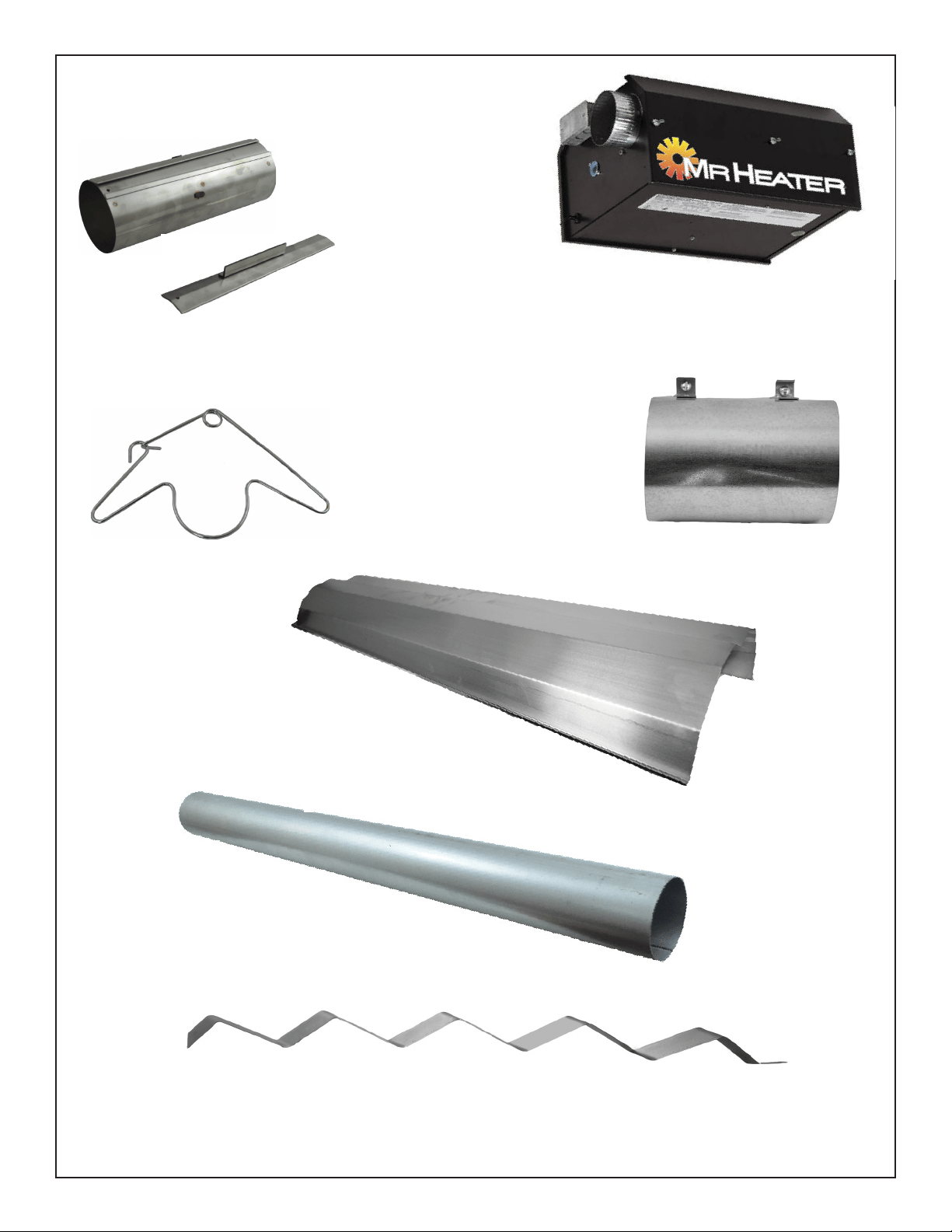
6
Mr. Heater Series Chauffe-
INSTRUCTIONS D'UTILISATION ET MANUEL DU PROPRIÉTAIRE
SECTION 3 : Installation et assemblage
COUPLAGEDUTUBE(14612)
CLÉPOURLECOUPLAGEDUTUBE
(14616)
SUPPORTDUTUBE
(14585P)
TUBED'ÉCHANGEURDECHALEUR3,05M(10PI)
(06413)
DÉFLECTEURTURBULATEUR1,5M(5PI)(03445)
DÉFLECTEURTURBULATEUR3M(10PI)(03447)
**NONINCLUSAVECTOUSLESMODÈLES**
RACCORDD'ÉVENT
(19021)
BOÎTEDUBRÛLEUR
RÉFLECTEUR3,05M
(10PI)(00418A)
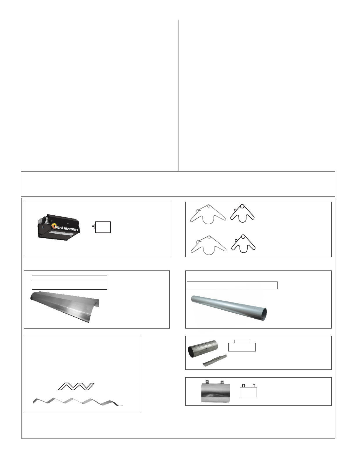
7
INSTRUCTIONS D'UTILISATION ET MANUEL DU PROPRIÉTAIRE
Mr. Heater Series Chauffe-
Procédures d’installation
Prenezavantageaumaximumdelastructuresupérieure
dubâtiment,despoutres,dessolives,despannes,etc.,
d'oùilestpossibledesuspendrelafournaise.Iln'existe
pasuneséquenceuniqued'installationdesconduites.
Lesobservationssurlesiterévèlenthabituellementune
séquencelogique.Commencezl'installationàladimension
lapluscritique.Celapourraitvoussauverdutemps.Faites
attentionauxportespivotantes,auxpontsroulants,aux
appareilsdelevagedevéhicules,etc.Lesréflecteursetles
conduitespeuventêtreinstallésaufuretàmesure.Réglez
soigneusementlapentedusystèmeàchaquepositionafin
demettreàniveaulafournaise.Réglezverslebasde1,2cm
(0,5po)paréloignementdelafournaisede6,1m(20pi).
NE PAS FAIRE
Testerlapressiondesconduitesdegazàl'aided'une
pressionélevée(plusde3,45KPa/0,5PSIG)sansfermer
lerobinetd'arrêtdelapressionélevée.Omettrecelapeut
endommagerlesbrûleurs.
Bâti du brûleur
Doittoujoursêtre
installéàl'horizontal.
Support pour tube et réflecteur
Installezimmédiatementaprèsle
premiercouplage.
Turbulateur
Le60-100kMr.Heaterutiliseunturbulateurde1,5m
(5pi)lorsqu'enfonctionnementavecunensemblede
tubede9,1m(30pi).
Leturbulateurestsituéàl'extrémitédu3etube.
Support pour tube et réflecteur
Suspendezlesystèmedeces
supports.Minimumdedeux(2)
requispartube.
Réflecteurs
Alternezlasuperposition
commeillustrésurl'aperçu.
Lalongueurduréflecteuret
laquantitédesuperposition
sontindiquées.
10pi2-1/2po
ENALUMINIUM
Tubes d'échangeur de
chaleur
Sontfournisenlongueurde
3,05m(10pi).
Assemblage du couplage du tube
Lecouplagedoitêtreorientéavecla
barredeglissementsurledessus,et
touslescouplagesdoivent
«pointer»danslamêmedirection.
AssemblezlescomposantsdelafournaisecommeillustrésauxFig.2a,2b,2c,2d.Lesconfigurationsdesréflecteursenoptionsontillustrées
àla(Fig.1).Installezlaquincaillerieappropriéedesuspension,lespincesdepoutres,lachaîneoulatigeauxemplacementsprédéterminés.Le
réglagedelalongueurdelachaîneoffreunpasuniforme.
À FAIRE
Familiarisez-vousaveclescodeslocauxetnationaux.
Développezuneprocédureplanifiéequiconserverles
matériauxetlamain-d'œuvresurlesite.
Vérifiezquetoutlematérieletl'équipementsontsurlesite
avantdecommencerl'installation.
Permettezuneexpansionthermiquedestubeschauds.
Installezleconnecteurdegazseulementcommeindiqué
danslesinstructions(voirlaFig.14àlapage16).
Ayezdesjointscoulissantsrequisentrelesréflecteurspour
lesempêcherdegauchiroudeseséparer.
Fournissez6,45cmca(1poca)d'ouvertured'airpour
chaque293Wd'entréedefournaise(maispasmoinsque
645cmca/100poca)dansdesespacesclos.Uneouverture
doitêtredansles30,5cm(12po)duhautetuneautredans
les30,5cm(12po)dubasdel'enceinte.
FIGURE 2 : Aperçu Mr. Heater
Adaptateur d'évent
Utilisépourfixerletube
d'échangeurdechaleuràla
conduited'évent.
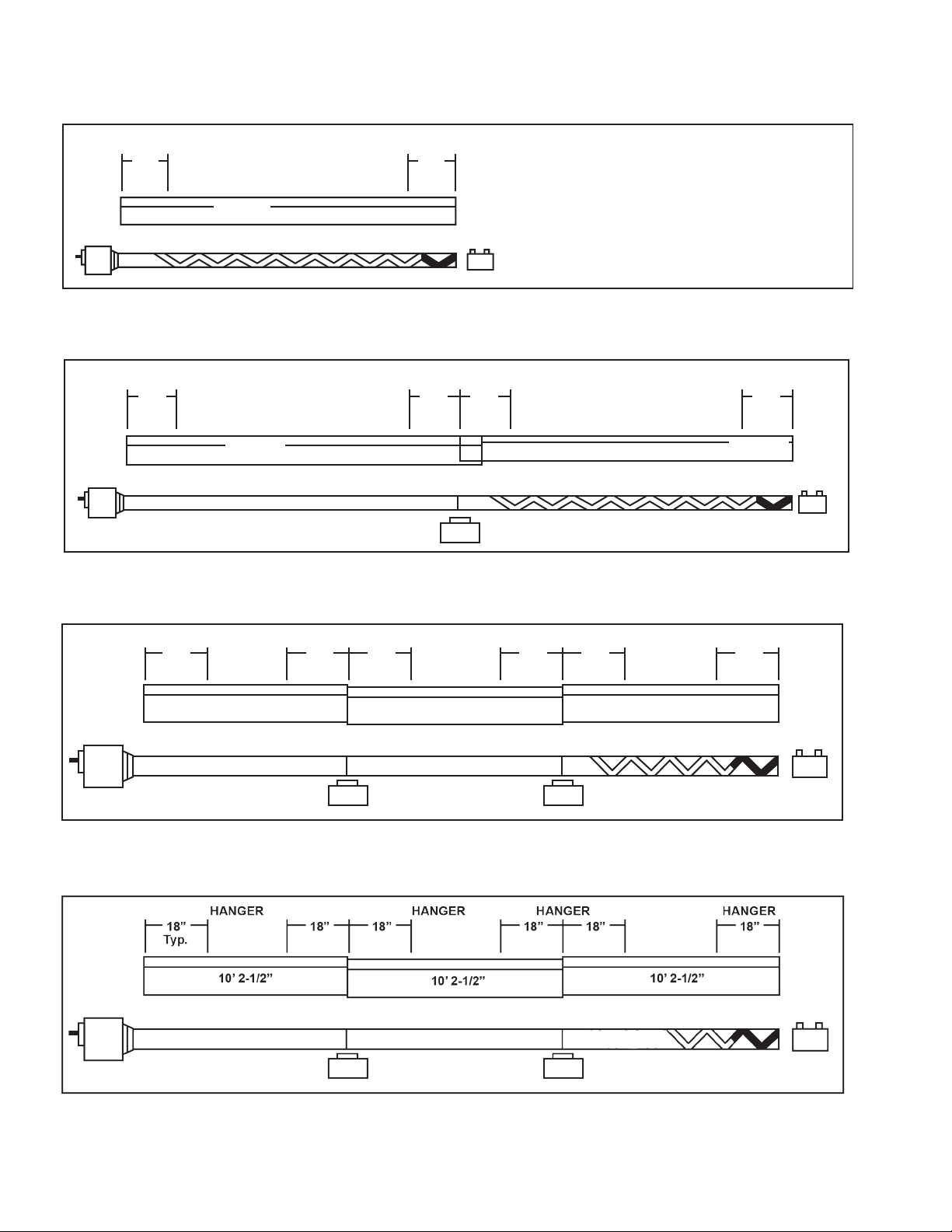
8
Mr. Heater Series Chauffe-
INSTRUCTIONS D'UTILISATION ET MANUEL DU PROPRIÉTAIRE
FIGURE 2A : Aperçu de l'assemblage Ener-Radiant modèle 40,000 BTULongueur de l'échangeur de 3,0 m (10 pi). Longueur
totale de la fournaise de 3,35 m (11 pi) 10 cm (4 po) . 2 points de suspension comme indiqué.
HANGER HANGER
18” 18”
10’ 2-1/2”
AL
UMINIZED
HANGER HANGER HANGER HANGER
18” 18” 18” 18”
10’ 2-1/2”
10’ 2-1/2”
ALUMINIZED
2-1/2” OVERLAY TYP
(1) Turbulator Sections
ALUMINIZED
18” 18” 18” 18” 18” 18”
10’ 2-1/2”
10’ 2-1/2”
10’ 2-1/2”
(1) Turbulator Sections
HANGER HANGER HANGER
Typ.
HANGER
ALUMINIZED ALUMINIZED
ENALUMINIUM
ENALUMINIUM ENALUMINIUM
ENALUMINIUM ENALUMINIUM
ENALUMINIUM
(1) SECTION DE TURBULATEUR DE 3,0 M (10 PI)
(1) SECTION DE TURBULATEUR DE 3,0 M (10 PI)
(1) SECTION DE TURBULATEUR DE 1,5 M (5 PI)
FIGURE 2B : Modèle Ener-Radiant MR. Heater Model 60,000 & 80,000 BTU
Longueur de l'échangeur de 6,0 m (20 pi). Longueur totale de la fournaise de 6,4 m (21 pi) - 10 cm (4 po). 4 points de
suspension comme indiqué.
FIGURE 2C : Modèle Ener-Radiant MR. Heater Model 80,000 BTU
Longueur de l'échangeur de 9,1 m (30 pi). Longueur totale de la fournaise de 9,4 m (31 pi) - 10 cm (4 po). 6 points de
suspension comme indiqué.
FIGURE 2D : Modèle Ener-Radiant MR. Heater Model 100,000 BTU
Longueur de l'échangeur de 9,1 m (30 pi). Longueur totale de la fournaise de 9,4 m (31 pi) - 10 cm (4 po). 6 points de
suspension comme indiqué.
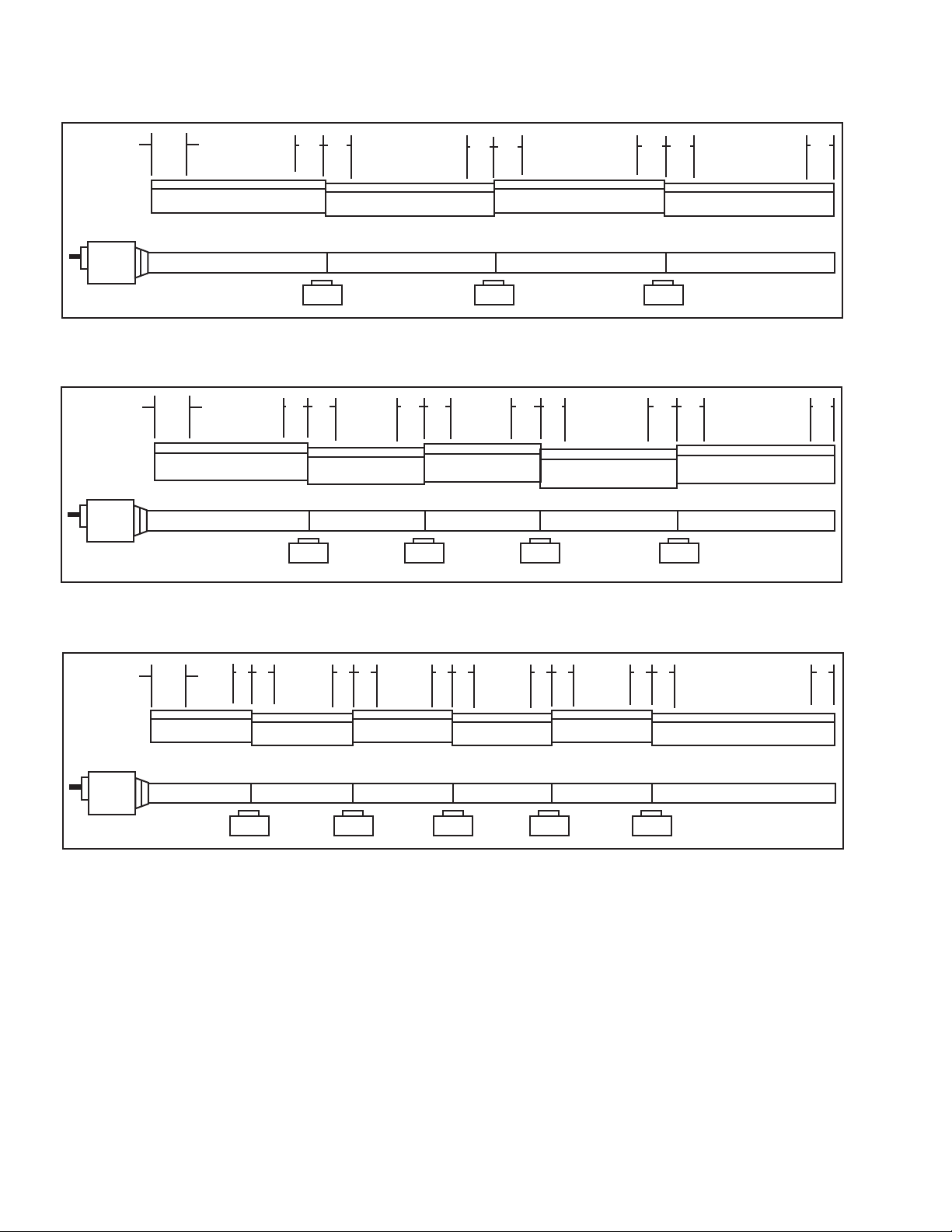
9
INSTRUCTIONS D'UTILISATION ET MANUEL DU PROPRIÉTAIRE
Mr. Heater Series Chauffe-
ALUMINIZED ALUMINIZED ALUMINIZED ALUMINIZED
18”
Typ.
18”
18”
18”
10’ 2-1/2”
10’ 2-1/2”
10’ 2-1/2”
10’ 2-1/2”
10’ 2-1/2” 10’ 2-1/2”
10’ 2-1/2”
10’ 2-1/2”
10’ 2-1/2”
18”
Typ.
ALUMINIZED ALUMINIZED ALUMINIZED ALUMINIZED ALUMINIZED
18” 18” 18” 18” 18” 18” 18” 18” 18”
10’ 2-1/2” 10’ 2-1/2” 10’ 2-1/2”
10’ 2-1/2” 10’ 2-1/2” 10’ 2-1/2”
18”
Typ.
ALUMINIZED ALUMINIZED ALUMINIZED ALUMINIZED ALUMINIZEDALUMINIZED
18” 18” 18” 18” 18” 18” 18” 18” 18” 18” 18”
FIGURE 2E : Modèle Ener-Radiant MR. Heater Model 100,000 BTU & 125,000 BTU
Longueur de l'échangeur de 12,2 m (40 pi). Longueur totale de la fournaise de 12,5 m (41 pi) - 10 cm (4 po). 8 points de
suspension comme indiqué.
18"
18"
18"
18"
18"
18"
18"
ENALUMINIUM ENALUMINIUM ENALUMINIUM ENALUMINIUM
ENALUMINIUM ENALUMINIUM ENALUMINIUM ENALUMINIUM ENALUMINIUM
FIGURE 2F : Modèle Ener-Radiant MR. Heater Model 125,000 BTU, 150,000 BTU, 175,000 BTU
Longueur de l'échangeur de 15,2 m (50 pi). Longueur totale de la fournaise de 15,5 m (51 pi) - 10 cm (4 po). 8 points de
suspension comme indiqué.
FIGURE 2G : Modèle Ener-Radiant MR. Heater Model 150,000 BTU, 175,000 BTU
Longueur de l'échangeur de 18,2 m (60 pi). Longueur totale de la fournaise de 18,5 m (51 pi) - 10 cm (4 po). 8 points de
suspension comme indiqué.
ENALUMINIUM ENALUMINIUM ENALUMINIUM ENALUMINIUM ENALUMINIUM ENALUMINIUM
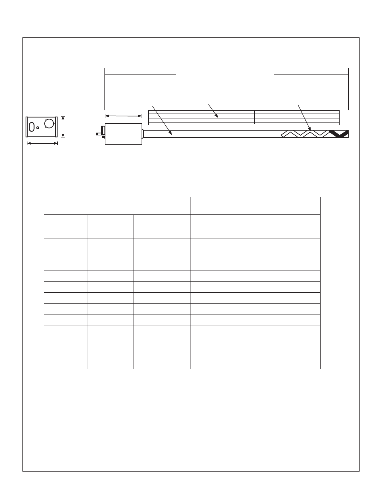
10
Mr. Heater Series Chauffe-
INSTRUCTIONS D'UTILISATION ET MANUEL DU PROPRIÉTAIRE
FIGURE 3 : Dimensions et hauteurs de montage suggérées du Ener-Radiant ER2STG
Longueur totale minimum
(voir le diagramme ci-dessous)
Vue de côté du
brûleur
Vue Arrière du brûleur
9.25"
(23.49cm)
9.25"(23.49cm)
17.75"(45.08)
Turbulateur
(SI REQUIS)
Tube d'échangeur de chaleu
Réecteur
Classifications du brûleur et longueurs de l'échangeur
de chaleur : (Gaz naturel et propane)
Hauteurs suggérées de montage
Puissance W
(BTU/H)
Faible-Forte
Longueur de
l'échangeur de
chaleur
Turbulateur
Longueur
minimale
totale
Espace min.
suggéré
Hauteur
typique de
montage
40,000 10pi 9pi
10pi-4pi 8pi-10pi 10’-14'
60,000 20pi 10pi
21pi-4pi 10pi-12pi 10’-14’
80,000 20pi 10pi
21pi-4pi 12pi-15pi 12pi-15pi
80,000 30pi 10pi
31pi-4pi 12pi-15pi 12pi-15pi
100,000 30pi 5pi
31pi-4pi 12pi-15pi 12pi-15pi
100,000 40pi Aucune
41pi-4pi 15pi-18pi 14pi-19pi
125,000 40pi Aucune
41pi-4pi 15pi-20pi 14pi-19pi
125,000 50pi Aucune
51pi-4pi 15pi-18pi 14pi-19pi
150,000 50pi Aucune
51pi-4pi 20pi-23pi 15pi-25pi
150,000 60pi Aucune
61pi-4pi 20pi-25pi 15pi-25pi
175,000 50pi Aucune
51pi-4pi 20pi-23pi 15pi-25pi
175,000 60pi Aucune
61pi-4pi 20pi-25pi 15pi-25pi
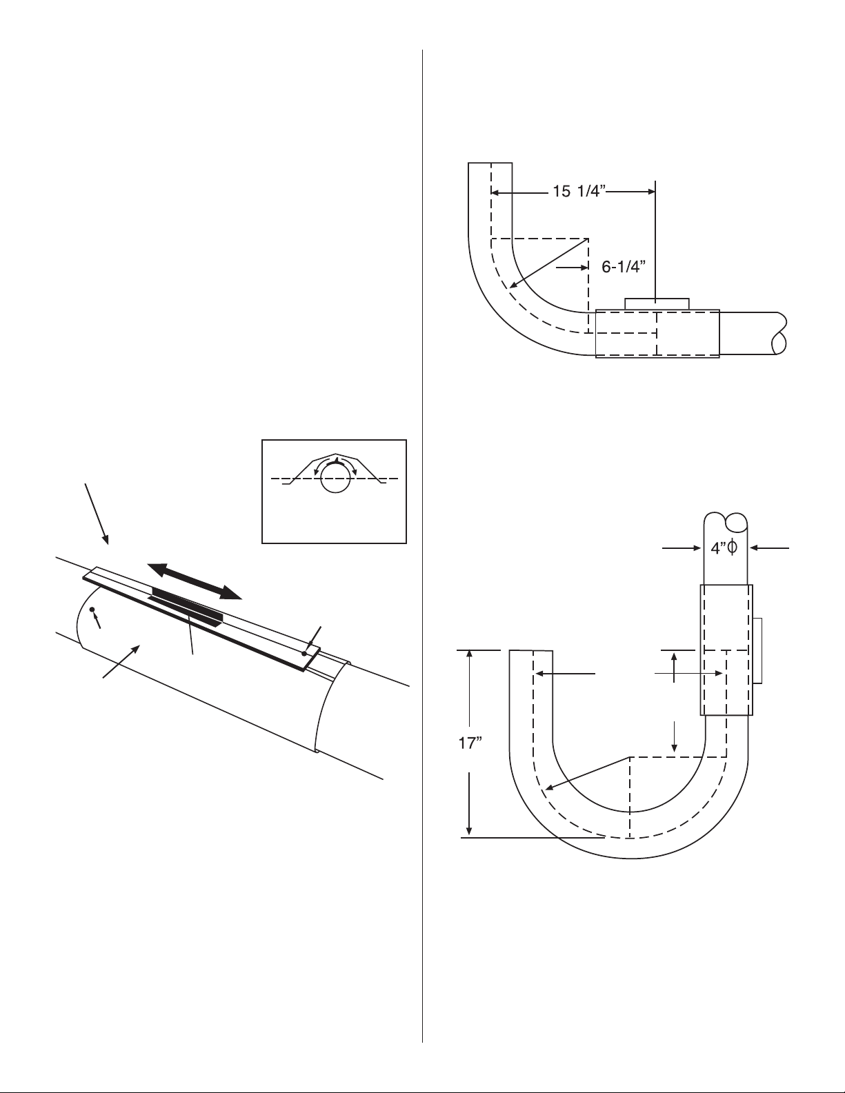
11
INSTRUCTIONS D'UTILISATION ET MANUEL DU PROPRIÉTAIRE
Mr. Heater Series Chauffe-
Couplages :Letubeetlesraccordsdutubesontreliéspar
descouplagesenveloppantsquipincentparun
dispositifdeverrouillagefuseléetfonctionnant
parunmarteau.Lesextrémitésdedépartdu
couplageetledispositifdeverrouillagesont
identifiéspardesorificesde6,4mm(1/4po),
quisontmisensembleaudébutdel'assemblage.
Assurez-vousquelesextrémitésdutubesonten
ligneetqu'elless'aboutentcontreleoulestiges
d'arrêtdanslecouplage.Labarredeglissement
doitêtremarteléeàunpointdefixationpourque
lecouplages'emboîteparfaitementaveclestubes.
Tropserrercausedeladistorsiondanslecouplage
oudanslalèvredelabarredeglissementàun
pointdiminuantlemaintiendelapossibilitéde
couplage.(VoirFig.4).
FIGURE 5 : Installation du coude et du couplage
ASSEMBLAGE DU COUPLAGE
Couplage (moins la clé) - 14612
Clé pour couplage - 14616
Orientcouplingsothat
theimpactblockisabove
tubecenterline.
COUPLAGEDUTUBE
CLÉPOURCOUPLAGE
FIGURE 4:
18" (45cm)
10"
(25cm)
(10cm)
(43cm)
9"
(22cm)
Radius
Orientezlecouplagedefaçonque
leblocd'impactsoitau-dessusde
lalignecentraledutube.
Desserrez
Serrez
Orifice1
Orifice2
Blocd'impact
Assemblagede
couplage
Lorsdel'assemblagedecouplage,prenez
notedel'emplacementdesorifices1et2
Ensembleducoude:StockL'ensembledecoudenoF106415comprend:
(1)coude,(1)couplageet.
Installezlecoudedanslaséquencedutuberadiantoù
lesplansindiquentunvirageà90°
Rayon de 22 cm (9 po)
Dimensionsduraccordducoude Coudeà90°
StockL'ensembledutubeenUnoFi106414comprend:
(1)tubeenU,(1)couplage.Installezlecoudedutube
enUdanslaséquencedutuberadiantoùlesplans
indiquentunvirageà180°..
Rayon de 22 cm (9 po)
DimensionsduraccorddutubeenU
TubeenUà180°
(38.73 CM)
(15.24 CM)
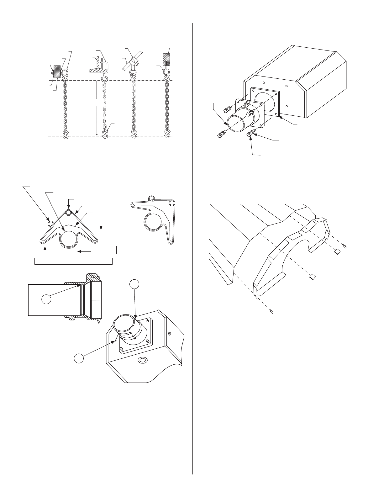
12
Mr. Heater Series Chauffe-
INSTRUCTIONS D'UTILISATION ET MANUEL DU PROPRIÉTAIRE
Ensembledechaîne-stockNo17370
Unensembledechaînesuspendunesectionde3,05m(10pi)de
tubeetunesectionde3,05m(10pi)deréflecteur.
FIGURE 7A : Support pour tube et réflecteur
FIGURE 7B : Détail du rebord de montage/Tube
1)Insérezletube06413danslemoulageavantaupoint(A).
2)Serrezlesvismarquées(B).
3)Aprèsquetoutesles(3)vissoientserrées,tournez-lesd'un
quartdetoursupplémentairepourfixerletubeenplace.
FIGURE 8 : Détail de la boîte du brûleur/Tube de transition
FIGURE 6 : Détails typiques de la suspension
Contre-écrou
Rondelle
Poutrede
bois
Rondelle
Crochetdevis
min.3/8po(10mm)
Poutre
enI
Pincede
poutre
Commerequis
Crochet
en S
Attachedela
solivedelabarre
Entretoise
Poutrede
béton
Dispositif
d'ancrage
Bridedemontage
Visdebouchon
StockNo98012
Rondelledeverrouillage
StockNo98527
Jointd'étanchéité
StockNo12397
Boîte du brûleur
(fenêtred'observationdela
flammefaisantfaceverslebas)
position DU rÉflecteUr À 45° (en option)
anneau de montage d'angle
tube radiant
anneau de montage horizontal
support
rÉflecteur
supÉrieur
cÔtÉ
position du rÉflecteur horizontal
(standard)
en-dessous
FIGURE 9 : Embout du réflecteur
Listedespièces
100419Emboutduréflecteur(qté1)
209369Attache-ressort(qté4)
Ensembledebrideno06428XL
L'ensemblecomprend:Bride,vis(4),rondellesdeverrouillage(4),
rondelle(1)
A
B
B

13
INSTRUCTIONS D'UTILISATION ET MANUEL DU PROPRIÉTAIRE
Mr. Heater Series Chauffe-
SECTION 4
Spécifications d'ingénierie
Lesystèmedechauffagetotalfournidoitêtrecertifiéauniveaude
laconceptionparleCSAselonladernièrerévisiond'ANSIZ83.20et
CSA2.34.
A. Brûleur et contrôles du brûleur
1.Lesbrûleursdoiventêtreenmesuredebrûleravecl'unedesop-
tionsdecombustiblecommespécifiéessurlesdocumentsd'achat
:Gaznatureloupropaneliquide.
2.Lesbrûleursdoiventpouvoirs'allumeràquelconquedestaux
d'entréecommespécifiés.
40,000BTU/Hr. 125,000BTU/Hr.
60,000BTU/Hr. 150,000BTU/Hr.
80,000BTU/Hr. 100,000BTU/Hr.
175,000BTU/Hr.
3.Lebrûleurdoitêtreéquipéd'unsystèmedecontrôled'allumage
desurfacechaudeaucarburedesiliconeàlogiquedirecteavec
undispositifd'allumageàarrêtà100%.L'alimentationfournie
àchaquebrûleurdoitêtrede110V,60Hz,phasesimple.Les
brûleursdoiventêtreclasséspour1,0A(fonctionnement)et5,0
A(démarrage)
4.Lebrûleurdoitêtreéquipéd'uneprotectiondemoteurde
surchauffethermique,d'unrotord'airéquilibré,d'uninterrupteur
depressiondesécuritéprouvantl'airdecombustion,etd'une
fenêtredevuepourobserverlaflamme.
5.Lorsquespécifié,dansdesenvironnementscontaminés,lebrûleur
doitêtreenmesuredefournirdel'airexterneàchaquebrûleur
pourlesupportdelacombustion.
6.Touslesbrûleursdoiventêtrepré-câblésavecunepriseetun
cordonélectriquemisàlaterre.
7.Auchoixduclient,lesbrûleurspeuventêtrecontrôléesavecun
thermostatdetensiondeligneenoptionouenoptionthermo-
statsbassetensionavecuntransformateurbassetensionrelais
approprié.
8.Fournituredegazauxbrûleursdoitêtreconformeàlasuivante
Connecteurdegaznaturelde12,7mm(0,5po).
NaturalGas: 4.6”W.C.MIN,7.0”W.C.MAX
LPGas: 11”W.C.MIN,14.0:W.C.MAX
B. Échangeur de chaleur
1.Letuberadiantdoitêtred'acieraluminiséd'undiamètre
de10cm(4po)fourniendessectionsde3,05m(10pi).
Lessectionsdoiventêtrejointespardescouplagesenvel-
oppantsd'acierinoxydable.
2.Leréflecteurdoitêtred'aluminiumetconçupourdiriger
toutelasortieradiantesouslalignecentralehorizontale
dutuberadiant.
3.Lesfournaisesdoiventêtreaéréesselonlesrecommanda-
tionsdufabricant.
Pression de MANIFOLD de gaz:
Natural Gas: 3.5” W.C.
LP Gas: 10.5” W.C.
Connecteurdegaznaturelde12,7mm(0,5po).
Pression de l'ENTRÉE de gaz :
Gaz naturel : 4,6 po colonne d'eau Min.
11,0 po colonne d'eau Max.
Gaz propane liquide : 11,0 po colonne d'eau Min.
14,0 po colonne d'eau Max.
Connecteurdegaznaturelde12,7mm(0,5po).
Caractéristiques électriques :(Touslesmodèles)
110V-60Hz
1,0A(fonctionnement)5,0A(démarrage)
Dimensions :
Grandeur de connexion des fumées……….........4 po.
Grandeur de connexion de l'air extérieur………4 po.

14
Mr. Heater Series Chauffe-
INSTRUCTIONS D'UTILISATION ET MANUEL DU PROPRIÉTAIRE
SECTION 5
Aération/Conduite
Exigences générales
Cettefournaisedoitêtreaéréeselonlesspécificationsconte-
nuesdanscemanueletselonlescodesnationauxquisuiventet
toutcodeétatique,provincialoulocalquis'applique:
•VoirlecodenationaldugazcombustibleNFPA54/ANSI
Z223.1-dernièrerévision.
•CANADA:Consulterlecoded'installationdupropaneetdu
gaznaturelCSAB149.1,dernièrerévision.
Lafournaisedoitêtreaéréeversl'extérieursoitverticalementou
horizontalement.
Unealimentationoptionnelled'airdel'extérieurpeutêtrediri-
géeverslafournaisehorizontalementouverticalement.
Assurez-vousquelaméthodechoisirpouraérerlafournaise
estconformeavectouslescodescommerequispourchaque
emplacementenparticulier.L'utilisationd'uneconduited'évent
àparoisimple(calibre26)estrecommandée.Uneconduite
d'éventàparoidoubleestrecommandéelorsdetoutpassage
dansletoitoulesmurs.
L'extrémitéd'échappementdelafournaisedoitaccepterune
conduited'éventde10cm(4po)àl'aidedel'adaptateurd'évent.
Installezl'adaptateurd'éventaveclacoutureverslehaut,bien
fixezenplacetouslesraccordsdel'éventavecaumoins3visà
métalno8x9,5mm(3/8po),etscelleztouslesraccordsavec
unscellantàbasedesiliconedetempératureélevée.
Silacondensationdanslaconduitedefuméesestunproblème,
lalongueurdecelle-cidoitêtreraccourcieouisolée.
Letuyaud'éventdoitêtrepenchéverslebasens'éloignantdu
brûleurde6mm(1/4po)pourchaque3m(10pi).
LONGUEURSDEL'ÉVENT:
•Longueurmaximaletotaledel'éventpermisseparsectionde
9,1m(30pi).
•Tuyaud'alimentationmaximald'airextérieurpermispar
sectionde9,1m(30pi).
•Lalongueurmaximaletotaledel'éventpluslongueurde
l'alimentationextérieuredel'airnedoiventpasdépasser
15,2m(50pi).
REMARQUE :
Untotaldedeux(2)coudesestpermispourlacombinaisonde
l'éventetdel'alimentationdel'airextérieur.Enlevez1,5m
(5pi)parcoudesupplémentairedelalongueurmaximale
permisesi3coudesouplussontutilisés.
Installezunelongueurminimaledroitede30cm(18po)de
tuyaupourlaprised'airoud'éventsoustoutToucoude.
Dispositions autres/Équipement optionnel pour le
fonctionnement avec et sans évent
a)Uneaérationsuffisantedoitêtrefournieparquantitéde
1887cm
3
/s(4CFM)par0,29kW(1000BTU/h)detauxde
combustion.
b)ConsultezANSIZ223.1-dernièrerévision,NFPA-54etles
codeslocauxpourdel'informationsupplémentaire.
c)L'utilisationd'unairdecombustionextérieuroptionneln'est
pasrecommandéavecdesfournaisesnonaéréesàcausede
considérationsdepression.Référez-vousàlapage16
Aération horizontale
a)QuatreconduitesdefuméesdeDEde10cm(4po)sont
requises.Unelongueurmaximalede9,1m(30pi)est
recommandée.
b)Touslesraccordsdeconduitedefuméesdoiventêtrescellés
àl'aided'unproduitconvenablecommeGeneralElectric
RTV106oulescellantadhésifàsiliconedetempérature
élevéerougePermatexForm-A-Gasket.
c)N'installezpastoutcoudeouraccordde45degrés
pourdirigerl'éventplusbasquelesystèmedeconduite
horizontale.
d)Lasortied'éventdoitêtreinstalléeàunehauteursuffisante
pourempêchersonblocagepardelaneige.
1)L'éventdoitsortirdubâtimentàaumoins2,1m(7pi)
au-dessusduniveaudusollorsquesituéprèsdetrottoirs
publics.
2)L'éventdoitsetermineràaumoins1m(3pi)au-dessusde
touteentréed'airforcéesituéedansles3m(10pi).
3)L'éventdoitsetermineràaumoins1,2m(4pi)en-
dessous,1,2m(4pi)horizontalementde,ou30,5cm(1
pi)au-dessusdetouteporte,fenêtre,ouentréepargravité
danstoutbâtiment.
4)Lasortied'éventdoitêtresituéeàaumoins30,5cm
(12po)detouteouvertureparlaquelledesgazd'évent
peuvententrerdanslebâtiment.
5)Lasortied'éventdoitêtreau-delàdetoutcombustible
suspendu.
Évent vertical
a)QuatreconduitesdefuméesDEde10cm(4po),d'une
longueurmaximalede9,1m(30pi)peuventêtreutilisées
commeillustréesaveclebouchond'éventapproprié.(Voir
lesexigencesgénéralessurcettepagepourdel'information
supplémentaire).
b)Unebagueisoléepeutêtrerequisepourpasserdansles
structurescombustibles(consultezlescodeslocaux).
c)Touslesraccordsdeconduitedefuméesdoiventêtrescellés
àl'aidedeproduitsconvenables(voirlesrecommandations
pourl'aérationhorizontale).
Aération commune
a)Lacoursehorizontaled'unéventnedoitjamaisdépasser75
%delahauteurverticaledel'évent.ConsultezANSIZ223.1
-dernièrerévision,NFA-54pourlesgrandeursappropriéeset
l'installationdel'évent.
b)Lazoneouvertedel'éventcommundoitêtreégaleàla
sommedelazoneouvertedeséventsindividuelsquiysont
connectés.(Voirletableauci-dessousetlesdiagrammes-
page14.)
c)Utilisezunéventàparoidoublecommerequis(vérifiezles
codes).
d)Touslesjointsdoiventêtrescellésàl'aidedeproduits
appropriés.
e)Lesconnexionsàunepilecommunedoiventêtre
positionnéesafind'éviteruneoppositiondirecteentrelesflux
desgazdecombustion.
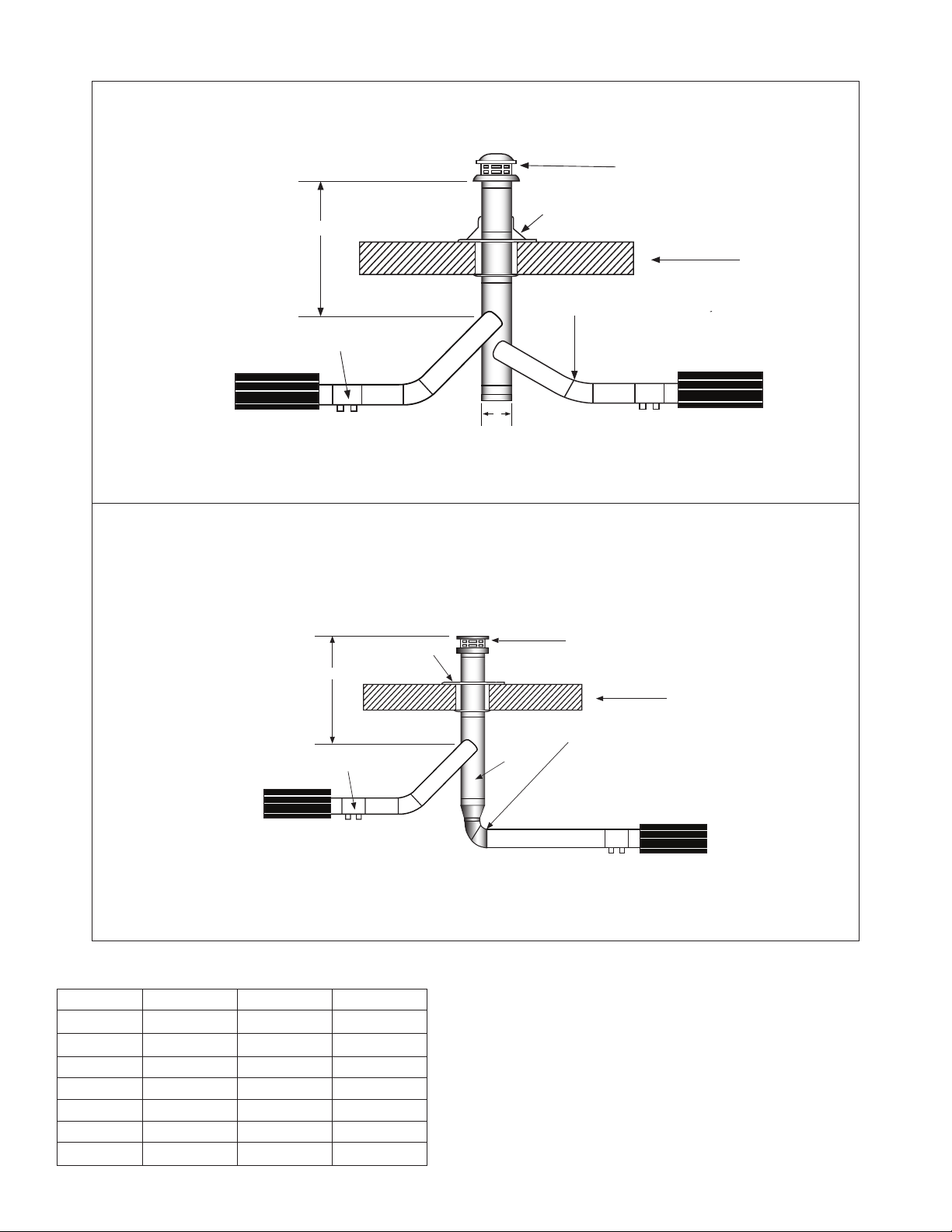
15
INSTRUCTIONS D'UTILISATION ET MANUEL DU PROPRIÉTAIRE
Mr. Heater Series Chauffe-
AÉRATION COMMUNE - (2) fournaises (horizontale et verticale)
SIDE VIEW
TOP VIEW
Type "B" Vent required outdoors.
Vent Adapter Stk. #19021
At least 1/4" per foot rise or pitch
must be maintained on horizontal
runs from heater to vent.
Roof
Secure all joints with 3 (minimum) #8 x 3/8"
sheet metal screws and seal all joints.
H
Approved Vent Cap
Type "B" Vent required outdoors.
Vent Adapter Stk. #19021
Outside Wall
H
Vent Cap
Flashing
Wall Thimble
(If Applicable)
Burner Box
Burner Box
Burner Box
Burner Box
Burner Box
Burner Box
D
Burner Box Burner Box
D
4” Aluminized steel Heat Exchange Tube
4” Aluminized steel Heat Exchange Tube
FIGURE 12 : Aération d'un toit commun
Type"B"Ventrequiredoutdoors.
VentAdapterStk.#19021
Securealljointswith3(minimum)#8x3/8"
sheetmetalscrewsandsealalljoints.
H
BurnerBox
BurnerBox
AÉRATION COMMUNE HORIZONTALE
AÉRATION COMMUNE VERTICALE
D
VUELATÉRALE
ÉventdetypeBrequispourl'extérieur.
Baguedemur
(siapplicable)
Capuchond'aération
Murextérieur
ÉventdetypeBrequispourl'extérieur.
Fixeztouslesraccordsavecunminimumde3visàmétal
no8x9,5mm(3/8po)etscelleztouslesraccords.
Boîtedubrûleur
Boîtedubrûleur
Adaptateurd'éventStockNo19021
Boîtedubrûleur
Adaptateurd'évent
StockNo19021
Capuchond'aérationapprouvé
Toit
Solin
Fixeztouslesraccordsavecunminimumde3visàmétal
no8x9,5mm(3/8po)etscelleztouslesraccords.
Boîtedubrûleur
Model# H=6ft. H=8ft. H=15ft.
40,000BTU
D=7" D=6" D=6"
60,000BTU
D=7" D=6" D=6"
80,000BTU
D=8" D=7" D=6"
100,000BTU
D=8" D=8" D=7"
125,000BTU
D=10" D=10" D=8"
150,00BTU
D=10" D=10" D=8"
175,000BTU
D=10" D=10" D=8"
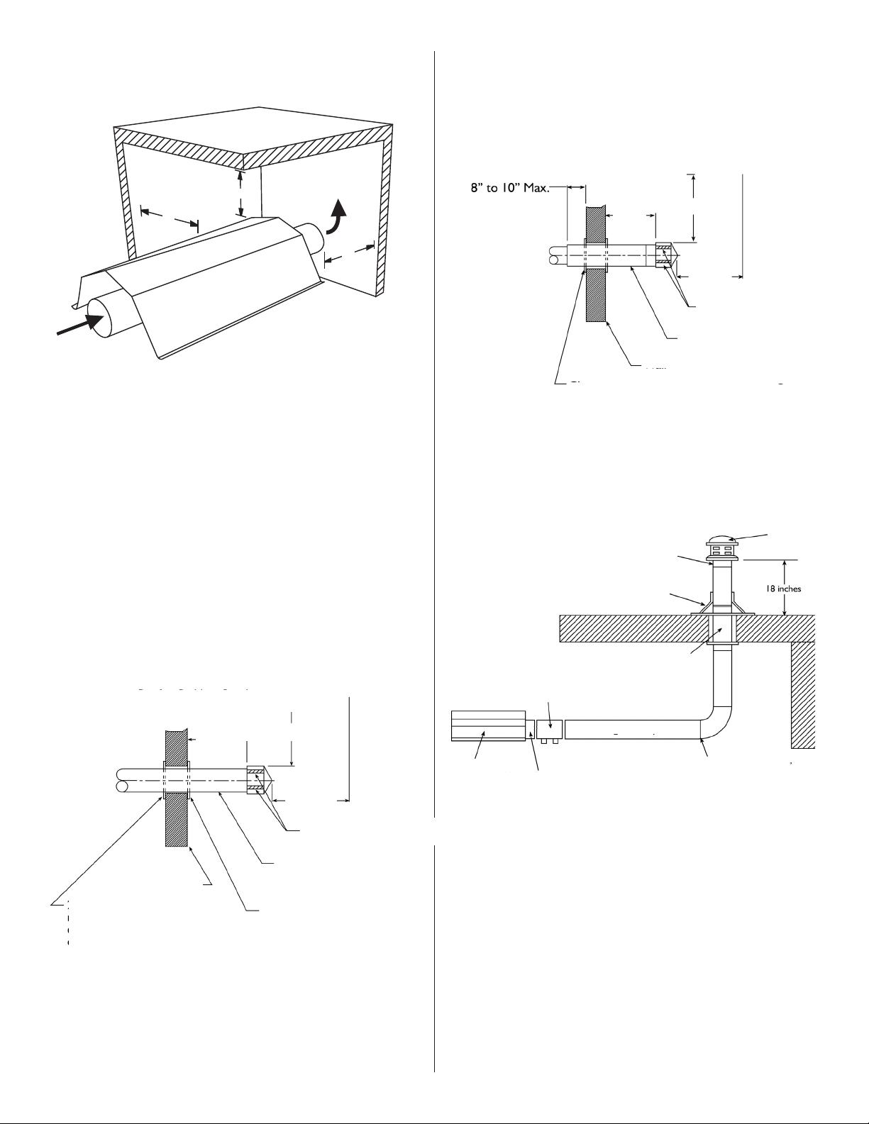
16
Mr. Heater Series Chauffe-
INSTRUCTIONS D'UTILISATION ET MANUEL DU PROPRIÉTAIRE
18" (45cm) Min. 3'-0" (91cm) Min.
8"(20cm) to 10"(25cm) Max.
6' (182cm) Min.
6' (182cm) Min.
2"(5cm) Clearance thimble
FIGURE 10 : Fonctionnement sans aération
1. 1.Uneaérationégaleà1887cm3/s(4CFM)partauxde
combustionde0,29kW(1000BTU/h)doitêtrefourniedans
desinstallationsdefournaisenonaérée.
2. 2.PourlesdimensionsAnonaérées,consultez(Fig.1-
espaceslibresminimumauxcombustibles).
3. 3.Cettefournaisenécessiteuneaérationdanslebâtiment
pourdiluerlesproduitsdecombustionetfournirdel'airfrais
pourunecombustionefficace.
FIGURE 10b : Paroi double
Coursed'éventàparoidouble
Extrémitédesortieàparoidouble
FIGURE 11 : Évent vertical
FIGURE 10A : Paroi simple
Coursed'éventàparoisimple
Extrémitédesortieàparoisimple
18 po (45 cm) min. 3 pi (91cm) min..
Bague d'espace libre de
5 cm (2 po)
Bague d'espace libre de
5 cm (2 po) requise
lorsque la conduite
se prolonge dans des
matériaux combustibles
Avancéedetoitoudebâtiment
Mur
Nivelezlaconduitedefuméesverslebas
versunesortiede6,4mm(1/4po)par
30,5cm(1pi)pourl'évacuationdela
condensation.
Notezlapositiondesouverturesdu
capuchond'aération
Parapetoubâtimentadjacent
Avancéedetoitoudebâtiment
Notezlapositiondesouverturesdu
capuchond'aération
Parapetoubâtimentadjacent
L'espacelibredoitêtrecommespécifiédansla
conduited'éventdetype«B».
Mur
Nivelezlaconduitedefuméesverslebas
versunesortiede6,4mm(1/4po)par
30,5cm(1pi)pourl'évacuationdela
condensation.
Éventdetype«B»requis
pourl'extérieur.
Solindutoit
Bagueapprouvée
(siapplicable)
Fournaise
Éventdesortiedelafournaise
Conduiteàparoisimple
Fixeztouslesraccordsavecunminimumde3
visàmétalno8x9,5mm(3/8po)etscellez
touslesraccords.
Capuchon
d'aération
36”
36”
A
(91cm)
(91cm)
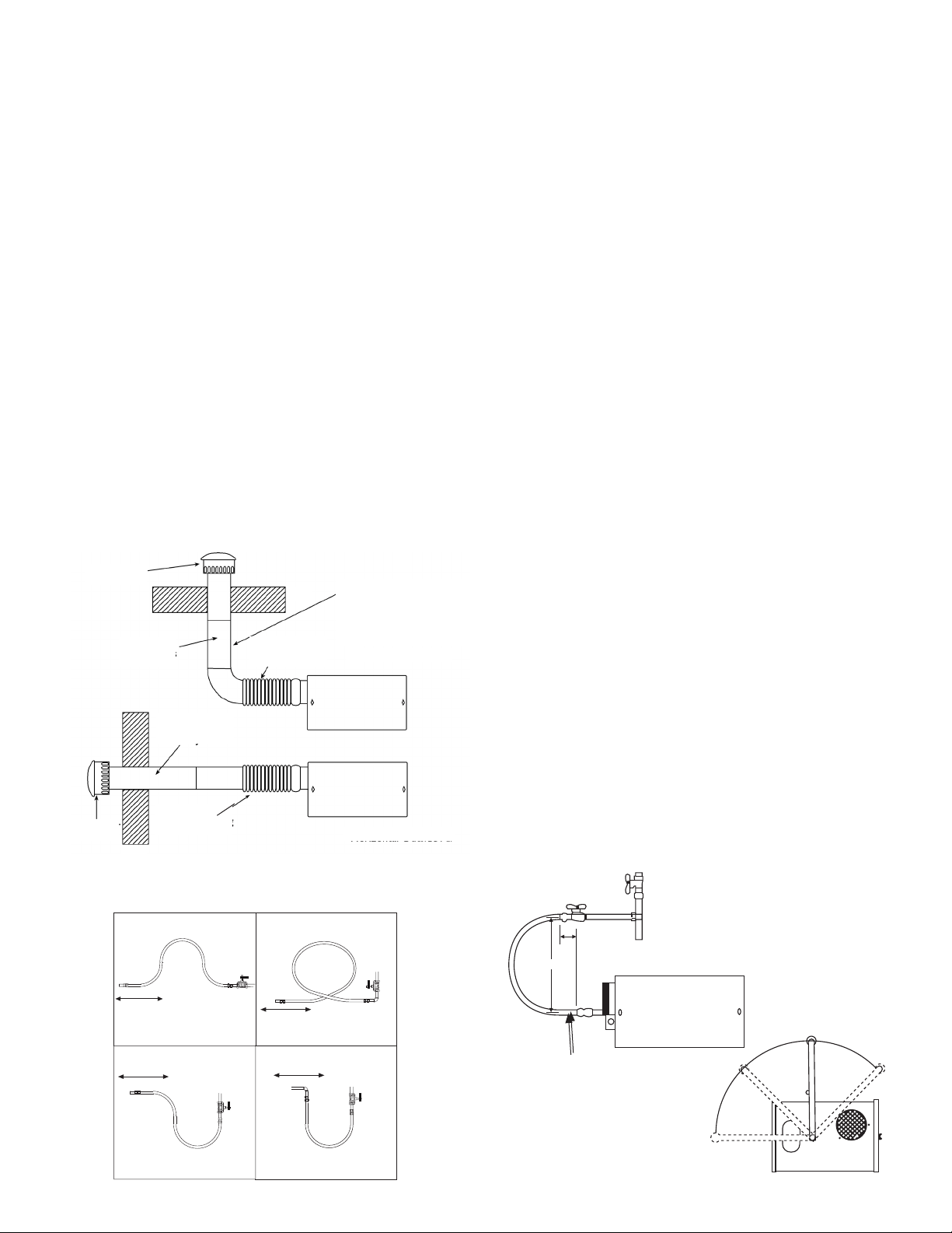
17
INSTRUCTIONS D'UTILISATION ET MANUEL DU PROPRIÉTAIRE
Mr. Heater Series Chauffe-
Shut-OffValvemustbeparallel
toburnergasinlet.The2”
displacementshownisforthecold
condition.Thisdisplacementmay
reducewhenthesystemisfired.
Shut–offValve
12 "
2"
1/2"StainlessSteelFlexGasConnector
Stk.#16401
90°
45°
0°
45°
Lavalved'arrêtdoitêtreparallèleàl'entréede
gazdubrûleur.Ledéplacementde5cm(2
po)illustréestpourdesconditionsfroides.Ce
déplacementpeutseréduirelorsdelamiseen
marchedusystème.
Valved'arrêt
Connecteurdegazflexibleenacierinoxydablede
12,7mm(1/2po)
StockNo16401
4 po (10 cm)
Scellez tous les
raccords
Heater Movement
Heater Movement
Heater Movement
Heater Movement
Sortie d'air
extérieure
Tuyau exible
Longueur de 15 à 30
cm (6 à 12 po)
Tuyau exible
Longueur de 15 à 30
cm (6 à 12 po)
Tuyau exible
Longueur de 15 à 30
cm (6 à 12 po)
Sortie d'air
extérieure
REMARQUE :
Las tuberías necesitan soporte La
conduite de fumées nécessite un
support supplémentaire. La conduite
exible ne soutient pas les colonnes
montantes et les sorties extérieures d'air
Air extérieur vertical
Air extérieur horizontal
FIGURE 14A : Connexion incorrecte de conduite de gaz avec
un connecteur de gaz flexible en acier inoxydable
Mur
Toit
Mouvementdelafournaise
Mouvementdelafournaise
Mouvementdelafournaise
Mouvementdelafournaise
MAUVAIS
MAUVAIS
MAUVAIS
MAUVAIS
Alimentation d'air extérieur de combustion
LafournaiseEner-RadiantER2STGestapprouvéepouruneinstallation
avecunsystèmeextérieurd'alimentationenair.Certainscomposés
commeleshydrocarbureshalogénésoud'autresproduitschimiques
corrosifsdansl'airpeuvententrerdansl'équipementetprovoquerun
tauxaccélérédecorrosiondecertainsdescomposantsdelafournaise.
L'utilisationdetelscomposéschimiquesprèsdel'enceintedoitêtre
évitée.
IMPORTANT : Si le bâtiment possède une légère pression
négative ou si des contaminants sont présents dans l'air, une
alimentation extérieure d'air de combustion vers les fournaises
est fortement recommandée.
Pourunealimentationextérieured'air,uneconduiteàparoisimple
d'unDEde10cm(4po)peutêtrefixéeàlafournaise.Laconduite
peutavoirunelongueurmaximalede9,1m(30pi)ouunelongueur
minimalede61cm(2pi)avecpasplusdedeux(2)coudes.(Voirles
exigencesgénéralesàlapage15pourplusd'informations.)
Laconduited'alimentationenairpeutdevoirêtreisoléepour
empêcherlaformationdecondensationsurlasurfaceexterne.La
sortieextérieured'airdoitêtrefixéesolidementàlaparoiextérieure
enperçantquatre(4)orificesd'undiamètrede6,4mm(1/4po)dans
lerebordextérieur.Desvisàboisoudesboulonsetdesmanchons
d'expansionpeuventêtreutiliséspourfixerlasortie.
UntuyauenPVC,un«tuyaudesécheuse»,ouunéquivalent,peut
êtreutiliséaulieud'uneconduited'éventstandard.
FIGURE 13 : Conduite d'alimentation d'air extérieure non
pressurisée
SECTION 6
Conduite de gaz
Lisezlesavertissementsapplicablesdansla(Section1)avantde
poursuivrel'installationdelaconduitedegaz.Uneinstallation
incorrectepeutentraînerdesdommagesauxbiens,desblessures
gravesetmêmelamort.
Lecompteurdoitêtreassezpuissantpoursupportertouslesbrûleurs
eninstallationplustouteautrechargereliée.Laconduitedegazqui
alimentelesystèmedoitêtreassezgrandpouralimenterlegazrequis
avecunebaissemaximaledepressionde1,25millibar(1/2pode
colonned'eau).Lorsquelaconduitedegazn'estpasinclusedansle
dessindesplans,lefournisseurlocaldegazaidegénéralementdansla
planificationdelaconduitedegaz.
Uneembasede12,7mm(1/2po)àchaqueemplacementdebrûleur
doitêtresituéeetorientéecommeillustréeàla(Figure14).Pour
vérifierlapressiondusystème,mettezuneembasebouchéedegaz
naturelde3,2mm(1/8po)danslaconduitedegazauniveaude
laconnexionaubrûleurlapluséloignéedel'alimentation.Avantde
brancherlesbrûleursausystèmed'alimentation,vérifiezquetousles
testsdepressionélevéedelaconduitedegazontétécomplétés.Ne
paseffectuezdetestsdepressionélevéesurlaconduitedegazavec
lesbrûleursbranchés.
Suivezcesinstructionspours'assurerd'uneinstallationprofessionnelle
del'alimentationengaz:
•Supportertouteslesconduitesdegazavecdesmatériauxde
suspensionadéquatspourlesconduites.
•Utiliserduferforgéoudesconduitesd'acierforgéetdesraccordsde
fermalléables.Touteslesconduitesdoiventêtreneuvesetexemptes
dedéfauts.Fraisezsoigneusementlesconduitesetlesextrémitésde
celles-cipourenleverlesobstaclesetlesbavures.
•Utiliseruncomposépourraccordrésistantaugaznaturelsurtous
lesfiletsdelaconduite.
•Vérifierlaconduiteetsesextrémitéspourtoutefuiteavecdemettre
l'équipementdechauffageenfonction.Lorsdelavérificationde
fuitesdegaz,utilisezunesolutiond'eausavonneuse:N'UTILISEZ
JAMAIS UNE FLAMME NUE.
Installezleconnecteurflexibledegazcommeillustré.Leconnecteur
flexibledegazaccommodel'expansiondusystèmedechauffageet
permetuneinstallationetunentretienfaciledubrûleur.
FIGURE 14 : Connexion de la conduite de gaz avec un connecteur
de gaz flexible en acier inoxydable
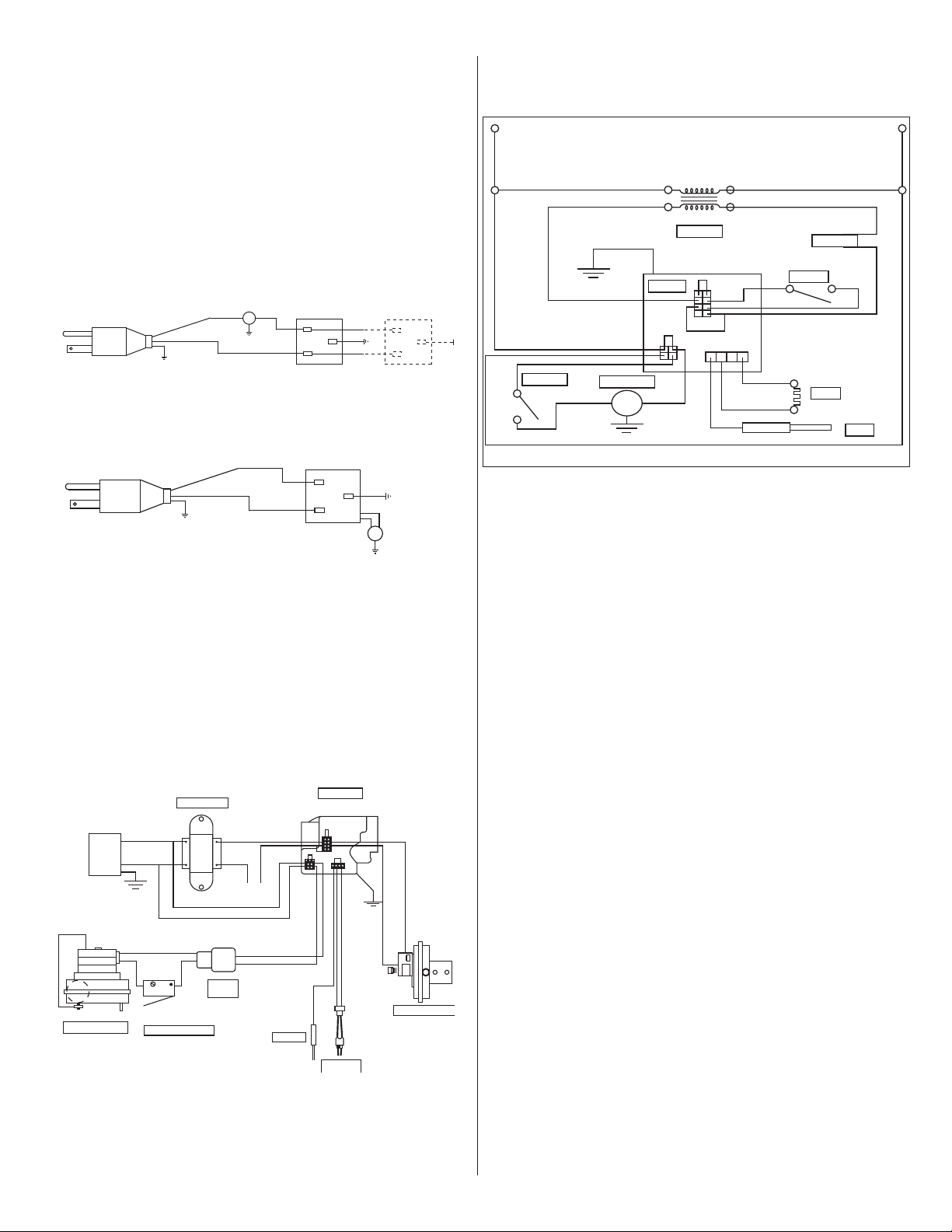
18
Mr. Heater Series Chauffe-
INSTRUCTIONS D'UTILISATION ET MANUEL DU PROPRIÉTAIRE
SECTION 7
Installation électrique
Leschauffagessontnormalementcontrôlésparlesthermostats.
Lesthermostatsdevoltagedelignesonttélégraphiésdirectement
(voirlechiffre15),lerecommandé24Vlesthermostatsutilisent
unéquipederelais(voirlechiffre16).Leschauffagesdoiventêtre
fondésconformémentàl'ANSI/NFPACodéÉlectriquenational-70-
ladernièreversion.Leschauffagespeuventaussiêtrecontrôlésavec
unchangementdevoltagedelignemanuelouunchangementde
compte-minutesàlaplaceduthermostat.
Chiffre 15: Installation électrique de
Thermostat de Voltage de Ligne
Chiffre 16: Installation électrique de
Thermostat de Voltage de Ligne Basse
Chiffre 21: MR. Heater Brûleur Diagramme d'Échelle
d'Installation électrique Intérieur
Chiffre 17: MR. Heater Brûleur Installation
électrique Intérieure
• Si du câblage d’origine fourni avec l’appareil de
chauage doit être remplacé, il faut utiliser du câblage
prévu pour une température nominale d’au moins 105 °C
et une tension de 600 V.
• Chaque brûleur doit être mis à la terre conformément à la
plus récente révision du National Electrical Code ANSI /
NFPA-70
VAC
120
120V
24V
Noir
Noir
Pourpre
Jaune
Jaune
Noir
Noir
Noir
Vert
Vert
Orange
Transformateur
Blanc
Blanc
Blanc
THERMOSTAT
Blanc
Bleu
Valve du Gaz
Changement Aérien
Allumage
électronique
Détecteur
Moteur / Ventilateur
Changement de Porte
Terminus
Bushing
H
N
Vert
Blanc
Noir
H
N
Vert
Blanc
Noir
T
T
Brûleurs
(maximum 1 par thermostat)
Brûleurs
(maximum 2 par thermostat)
Circuit d'alimentation
120 volts - 60 Hz
Circuit d'alimentation
120 volts - 60 Hz
H
N
Vert
Blanc
Noir
H
N
Vert
Blanc
Noir
T
T
Brûleurs
(maximum 1 par thermostat)
Brûleurs
(maximum 2 par thermostat)
Circuit d'alimentation
120 volts - 60 Hz
Circuit d'alimentation
120 volts - 60 Hz
120V
L2
(NEUTRAL)
White
White
White
White
White
White
Gray
Orange
Transfomer
Thermostat
Air Switch
Gas Valve
Door Switch
Motor / Blower
Ignitor
Sensor
Blue
Yellow
Yellow
Purple
Black
Black
Black
Black
L2 (HOT)
24V

19
INSTRUCTIONS D'UTILISATION ET MANUEL DU PROPRIÉTAIRE
Mr. Heater Series Chauffe-
SECTION 8
Opération et Maintenance
Ordre d'Opération
1. Augmentez le réglage du thermostat. Lorsque le
thermostat donne un signal de chauage, le moteur
du ventilateur se met sous tension.
2. Lorsque le moteur approche de la vitesse de rotation
nominale, l’interrupteur à air se ferme et actionne le
module d’allumage.
3. Le module d’allumage se met sous tension et l’allumeur
commence à produire des étincelles.
4. À ce stade, l’électrovanne à gaz se met sous tension.
5. Durant la phase nale de la séquence, l’allumeur est mis
hors tension et devient un détecteur de amme.
6. Si une amme est détectée, l’électrovanne à gaz reste
ouverte. Lorsque la demande de chauage est satisfaite et
que le mécanisme de commande du système met hors
tension l’alimentation de ligne du brûleur, les vannes à
gaz se ferment.
7. Si aucune amme n’est détectée sur un module à un seul
essai, l’électrovanne à gaz se ferme et le module va se
verrouiller jusqu’à sa réinitialisation. La réinitialisation se
fait en supprimant l’alimentation du module pendant au
moins cinq (5) secondes (cycle de thermostat requis).
8. Si aucune amme n’est détectée sur un module à trois
essais, l’électrovanne à gaz se ferme et une phase de
vidange commence. Après la vidange, le module met
l’allumeur sous tension pour une deuxième période de
réchauage et un deuxième essai d’allumage. Si une
amme n’est toujours pas créée, un troisième et dernier
cycle de vidange, réchauage et essai commence. Après
trois essais, le module va se verrouiller jusqu’à la
réinitialisation. La réinitialisation se fait en supprimant
l’alimentation du module pendant au moins cinq
(5) secondes (cycle de thermostat requis).
9. Sur un module à trois essais, si la amme est
créée et perdue lors du premier ou deuxième essai,
l’électrovanne à gaz se ferme, un troisième cycle de
vidange, réchauage et essai d’allumage a lieu; trois
essais d’allumage seulement sont autorisés par cycle de
thermostat.
Maintenance
Pour assurer un bon fonctionnement, les méthodes d’entretien
suivantes doivent être respectées avant chaque saison de
chauage.
1. Vériez si l’alimentation électrique et l’alimentation
en gaz sont bien fermées avant de procéder à une
réparation ou un entretien.
2. Vériez l’état de la volute et du moteur du ventilateur.
Les saletés ou poussières peuvent être souées à l’air
comprimé ou éliminées à l’aide d’un aspirateur.
3. Vériez l’état du brûleur. Enlevez soigneusement les
poussières ou débris de l’intérieur du boîtier ou du godet
du brûleur.
4. Inspectez l’allumeur. Remplacez l’allumeur s’il contient
trop de résidus de carbone, s’il est érodé, cassé ou
comporte un autre défaut.
5. Vériez l’intérieur du tube d’allumage à l’aide d’une
lampe-torche. Si des dépôts de carbone ou de calamine
sont présents, grattez-les avec une brosse métallique,
une tige ou une plaque métallique xée à un pieu en
bois.
6. Vériez si le voyant d’observation du brûleur est propre,
sans trous ni ssures. Nettoyez-le ou remplacez-le au
besoin.
7. Vériez le conduit d’évacuation pour détecter la présence
de suie ou de saletés. Après l’avoir nettoyé au besoin,
reconnectez le conduit d’évacuation à l’appareil de
chauage.
8. Nettoyez les surfaces extérieures de l’appareil de
chauage en les essuyant à l’aide d’un linge humide.
9. Une agence d’entretien qualiée doit être contactée pour
les services autres que l’entretien régulier.
10. Vériez le raccordement de ventilation et l’arrivée d’air
frais pour voir s’ils ne se sont pas bouchés pendant la
saison sans chauage. Si l’un des tuyaux est bouché,
l’interrupteur à air ne va pas se fermer et le chauage ne
va pas fonctionner.
Dépannage
ATTENTION : Avant d’ouvrir la porte du
brûleur du Mr. Heater® XL pour procéder
à un entretien ou une réparation, vériez
si l’alimentation en gaz de l’appareil de
chauage est bien fermée et si le cordon
électrique du boîtier du brûleur est
débranché.
Le moteur du
ventilateur ne
fonctionne pas:
1.Lethermostatdonne-t-ilunsignalde
chauffage?
2.Mesurez-vous115Vàlaconnexion
d’alimentation?
3.Vérifiezl’étanchéitédesdeuxportes
latérales.
4.Vérifiezsileventilateurn’estpas
bloqué,remplacez-leaubesoin.
L’allumeur ne produit
pas d’étincelles:
1.Vérifiezsil’allumeurn’estpas
endommagé,remplacez-leaubesoin.
2.Vérifiezlarésistanceàl’allumeur.
3.Vérifiezsil’arrivéeetlasortied’airne
sontpasbouchées.
4.Vérifiezlecâblageetles
raccordementsdestuyauxà
l’interrupteuràair,remplacez-lesau
besoin.
5.Vérifiezlestensionsauprimaire
etausecondairedutransformateur,
remplacez-leaubesoin.
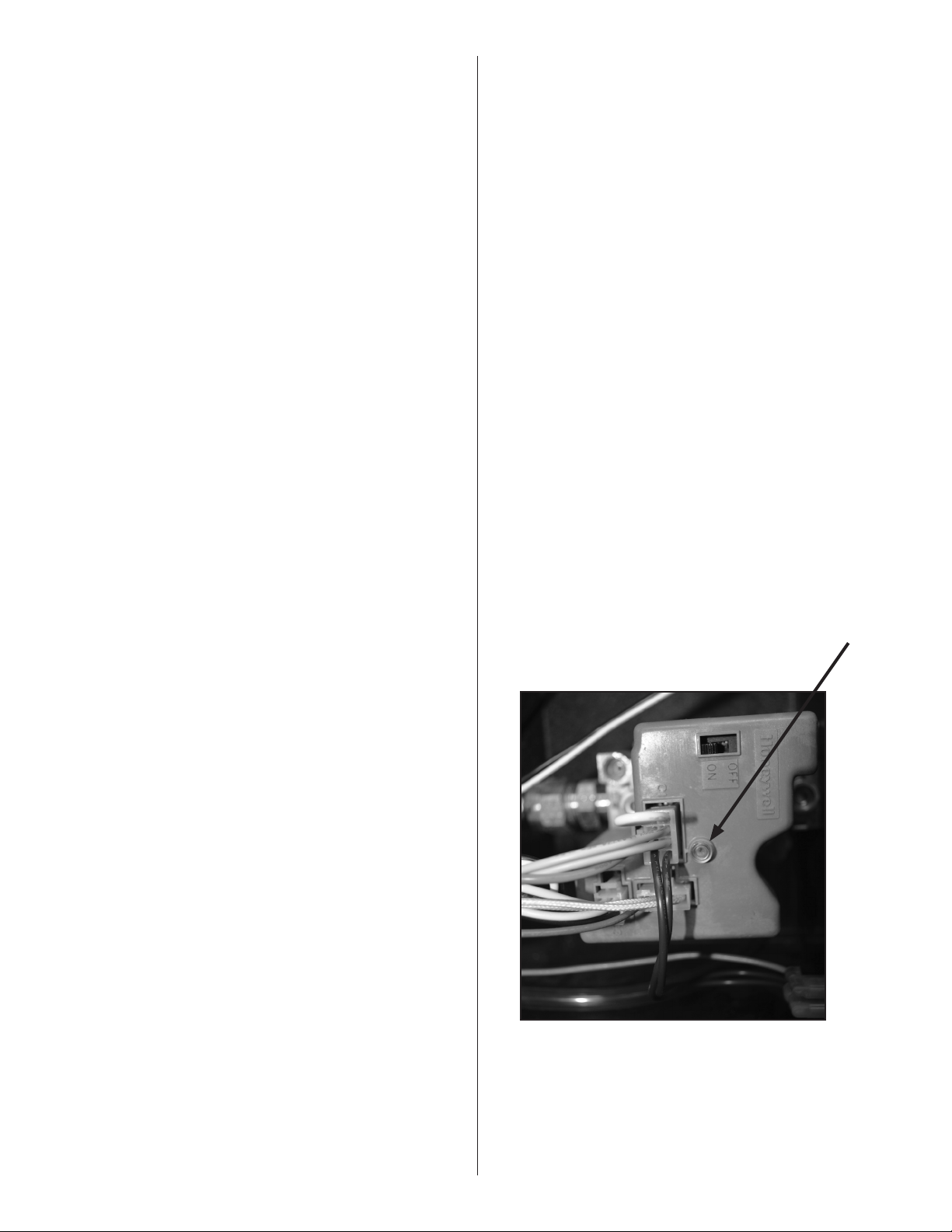
20
Mr. Heater Series Chauffe-
INSTRUCTIONS D'UTILISATION ET MANUEL DU PROPRIÉTAIRE
LED
HoneywellSmartValve
La vanne ne s’ouvre
pas:
1.Lapressiondegazenavaldela
commandedegazpeutsemesurer
àl’aided’unmanomètreenla
raccordantàlaprisedepressionsur
lacommande.
2.Vérifiezsilavannemanuelle
d’alimentationengazdel’appareil
dechauffageestouverte(ON).
3.Vérifiezsileboutondelavanne
manuellesurlacommandedegazde
l’appareilestouvert(ON).
4.Lapressiond’alimentationengaz
peutêtrevérifiéeàlaprisede
pressionNPTde1/8posurlavanne
manuelleexternedel’appareilde
chauffage.
5.Vérifiezsilacommandedegaz
s’ouvre:unepressiond’admission
nulleindiquequelavanneest
fermée.
Silavanneestfermée,c’estque
l’électrovanneàgazestferméeouque
l’allumageestdéfectueux.
AVERTISSEMENT! Nepas
déconnecterlesfilsdeterreà
l’intérieurdel’appareildechauffage.
Nepasintervertirlesconducteurs
misàlaterreetnonmisàlaterre
surletransformateuroulemodule
d’allumage.
Le brûleur ne s’allume
pas:
1.Vérifiezsilesconduitesdegazont
étécorrectementvidangéesdel’air.
2.Vérifiezlapressionàl’entréeetàla
sortiependantlaphased’allumage.
Lapressiond'arrivéenaturelledevrait
être4.6”.
Lapressiond'issuenaturelledevrait
être3.5”.
Lapressiondegaznaturelàl’entrée
doitêtrede117mmd’eau
Lapressiondegaznaturelàlasortie
doitêtrede88,9mmd’eau
3.Vérifiezsil’orificeestcorrect.
Le brûleur ne reste pas
allumé:
1.Vérifiezlacontinuitédufildeterre.
2.Vérifiezlecâblageinternedubrûleur
pourvoirsidesfilsdeconnexion
n’ontpasétéinversés.
3.Vérifiezl’isolationsurlesfilsde
connexiondel’allumeur.
4.Remplacezlemoduleaubesoin.
Honeywell Valve LED Status
Lechauffe-sérieTubeMR.Heaterestéquipéd'unevalveintelligente
Honeywell.Cettevanneaunprogrammedediagnosticintégré,ce
quiaideraàdépannageencasd'unproblèmeliéàlavalve.LaLED
ou(diodeélectroluminescente)estsituésurlapartiesupérieuredela
soupapecommereprésentésurlafigureci-dessous.Lesindications
d'étatLEDsonténumérésci-dessouspouraideràlarésolutiondes
problèmes.
Chiffre 22:
OFF INDICATED
Off Nonalimentationdelacommande
Bright-Dim Fonctionnementnormal.
Cetteindicationmontrechaquefoisquelesystème
estsoustension,àmoinsquequelqueévénement
anormalaeulieu.
2-Flashes Airflowfournissantcommutateurrestefermé
pendantplusde30secondesaprèsl'appeldechaleur
commence(commutateurd'airfournissantbloquéen
positionfermée.)
3-Flashes Airflowfournissantcommutateurresteouvert
pendantplusde30secondesaprèslasoufflerie
d'airdecombustionestalimenté-ousouffleriene
dynamiserpas.4-FlashesWhitejumperwireisloose.
5-Flashes Signaldeflammedétectéehorsdelaséquence
correcte.
6-Flashes Lockoutsystème.
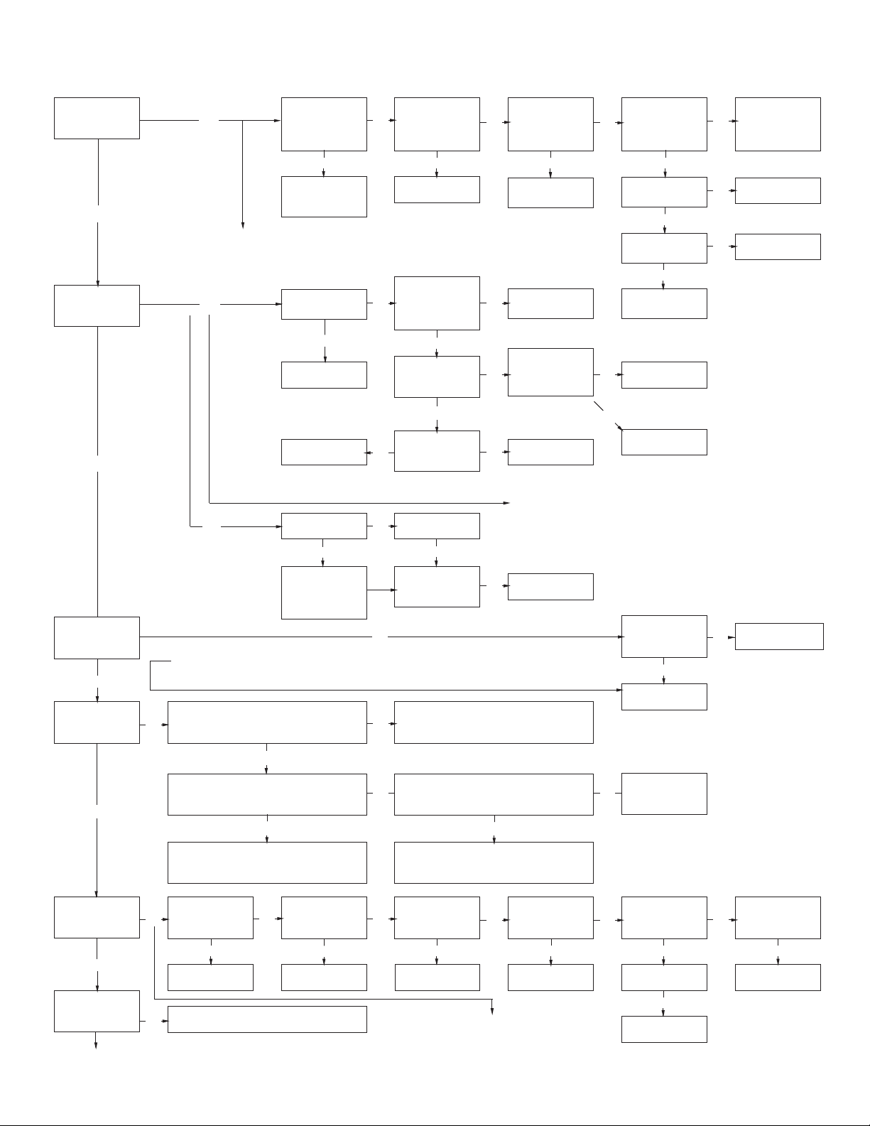
21
INSTRUCTIONS D'UTILISATION ET MANUEL DU PROPRIÉTAIRE
Mr. Heater Series Chauffe-
SECTION 9 : Guide de dépannage. Mr. Heater
DÉMARRAGE
Est-cequele
thermostatallumele
ventilateur?
Oui
Est-cequel'allumeur
seréchauffeet
rougit?
Oui
Non
Vérifiezlethermostat
etlecâblage.Est-ce
quel'alimentationvers
l'appareilestde110V?
Non
Trouvezlaraisondu
problèmeélectrique.
Vérifiezl'indicateurdelaDELsurlescommandesd'allumagepour
toutedéfaillance.Consultezletestdumoduled'allumageàlapage
19pourdéterminerleproblème.
Non
Est-cequelapriseoula
sortied'estestbloquée?
Oui
Retireztoute
obstruction.
Vérifiezlecâblageet
lesconnexions
Non
Est-cequel'allumeur
estendommagé?
Non
Vérifiezlatensionau
niveaudel'allumeur.
Est-cequelatensionest
de110Vlorsducycle
d'allumage?
Oui
Est-cequelaporte
latéraleduventilateur
enplace?
Non
Remplacezlaporte
Non
Vérifiezlecâblageet
lesconnexionsdetuyau
versleclapetd'air.
Sont-ilsOK?
Sí
Est-cequela
tensionauniveau
dutransformateur
secondairede24V?
Non
Est-cequelatensionau
niveaudutransformateur
primaireestde120V?
Remplacez
l'allumeur.
Oui
Non
Est-cequelarésistance
dansl'allumeur40à75
ohms?
Retirezlaporte.Est-ceque
latensionàl'interrupteur
delaporte110V?
Oui
Non
Vérifiezlatensionau
niveaudescommandes
d'allumage
Remplacezlecâblage
oulaconnexionde
tuyau.
Non
Oui
Remplacezle
transformateur
Oui
Vérifiezlesconnexions
desfils.
Oui
Abaissezl'interrupteur.
Est-cequele
ventilateursemeten
marche?
Oui
Oui
Non
Vérifiezlatensiondu
moteur.Est-ellede
110V?
Oui
Est-cequele
ventilateurestbloqué?
Non
Remplacezlemoteur
duventilateur.
Remplacezl'interrupteur
depression.
Oui
Remplacezlemodule
d'allumage.
Non
Vérifiezl'indicateurdelaDELsurlemodule
d'allumagepourtoutedéfaillance.Consultezle
testdumoduled'allumageàlapage19pour
déterminerleproblème.
Vérifiezsilaportese
fermebienenplace.Si
elleestendommagée,
remplacez-la.
Remplacezl'interrupteur.
Non
Retireztouteobstruction.
Oui
Aprèslapériodede
réchauffementde
l'allumeur,est-cequela
soupapeclique?
Oui
Est-cequelebrûleur
s'allume?
Oui
Est-cequelebrûleur
resteallumé?
Oui
Est-cequelebrûleur
fonctionnejusqu'àce
quel'appelpourdela
chaleursetermine?
Siunproblèmeexistetoujours,contacterleserviceàlaclientèledes
produitstechniquesMr.Heater,Incau1800251-0001
Non
Lemoduled'allumagevérifiel'étatdel'interrupteurdetestduventilateur,lescontactsdoiventnoterun
changementavecchaquecycled'allumage.Placeruneconnexionhorsdelaséquencedel'interrupteur
donneunedéfaillanceavecl'indicateurDELquiclignotedeuxfois.
Est-cequelesconduitesdegazontété
purgéesdeleurair?
Non
Non
Oui
Vérifiezlapressiondugazd'entrée.Est-cequela
pressionestcorrecte?Référez-vousàlapage12pour
labonnepressionpourl'appareil.
Oui
Vérifiezl'arrêtdugazd'entrée.Réglezlerégulateur.
Communiquezaveclefournisseurdegaz
Est-cequela
continuitédufilde
miseàlaterreOK?
Non
L'interrupteursurlasoupapedegazdoitêtreen
positionouverteetlaconduitepurgéedesonair.
Non
Réparezlecâblage.
Non
Vérifiezlacontinuitédufildemiseàlaterre.
Vérifiezlethermostat.
Vérifiezlapressiondesgazdesortielorsdu
cycled'allumage.Référez-vousàlapage12pour
labonnepression
Oui
Ajustezàlabonnepression.
Non
Est-cequeL1etL2
sontinversés?
Oui
Oui
Réparezlecâblage.
Est-cequelecâblage
auniveaudumodule
d'allumageOK?
Non
Réparezlecâblage.
Est-cequel'isolationsur
lefildudétecteurOK?
Non
Réparezlecâblage.
Non
Oui
Oui
Est-cequelesfils
verslescommandes
d'allumagesontOK?
Oui
Remplacezle
moduled'allumage.
Non
Remplacez/réparez
lesfils.
Oui
Vérifiezpourunorifice
debrûleuretune
plaqued'airadéquates.
Est-cequeledétecteur
estcorrectement
positionné?
Oui
Est-cequeledétecteur
estsale?
Non
Remplacezledétecteur.
Non
Réparation/
Remplacement
Oui
Nettoyez-le.
Vérifiezlacontinuitédufildemiseàlaterre.Vérifiez
lethermostat.Uneindicationdedéfaillancedetrois
clignotementspeutsignifierquelecircuitdedétectionde
laflammenefonctionnepascorrectement.Effectuezla
sériesuivantedevérificationspourcorrigerleproblème.
Non
Filsdeconnexionau
niveaudel'interrupteur
depression.Est-ceque
l'allumeurrougit?
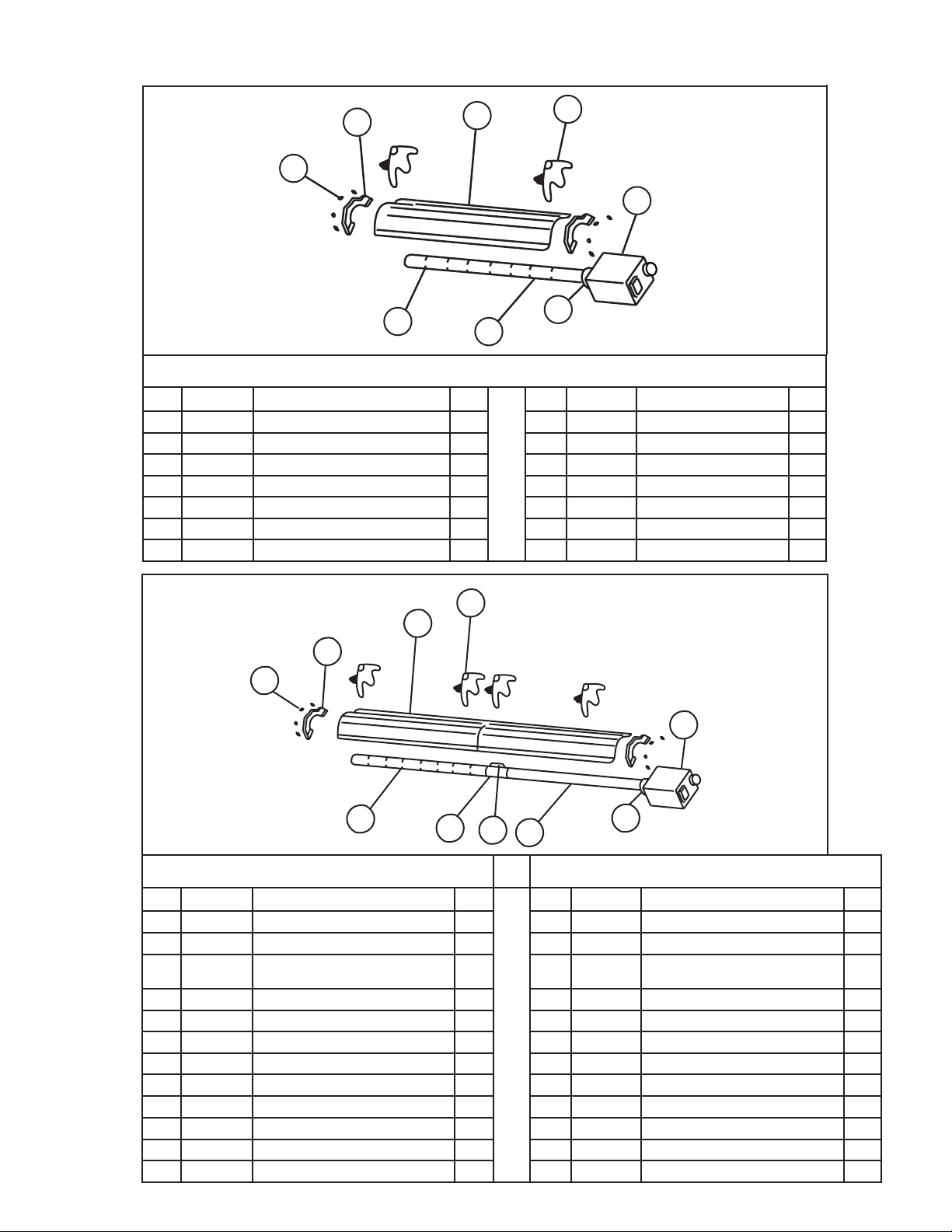
22
Mr. Heater Series Chauffe-
INSTRUCTIONS D'UTILISATION ET MANUEL DU PROPRIÉTAIRE
Parts List for MR. Heater Tube Heaters
60,000 BTU
80,000 BTU
Item Stock # Description QTY Item Stock# Description QTY
1 F102650XL 60,000BTUNG/BRNet
Boît
1 1 F102652XL 80,000BTULP/BRNet
Boît
1
F102651XL 60,000BTULP/BRNet
Boît
1 F102653XL 80,000BTUNG/BRNet
Boît
1
2 F106404XL 60,000BTU/
Ensembledetubede6m
(20pi)
1 2 F106404XL 80,000BTU,/
Ensembledetubede6m
(20pi)
1
06413 TubeH.E.DE10cm(4po)x3m(10pi)' 2 06413 TubeH.E.DE10cm(4po)x3m(10pi)' 2
3 00418A
Réflecteur
2 3 00418A
Réflecteur
2
4 03445
Déflecteurdeturbulateurde3m(10pi)
1 4 03445
Déflecteurdeturbulateurde3m(10pi)
1
5 14585P
Étrier
4 5 14585P Support 4
6 02753
Rebordavant
6 02753
Rebordavant
7 14 612 Couplagedutube 1 7 14 612 Couplagedutube 1
8 14 616
Clépourlecouplagedutube
1 8 14 616
Clépourlecouplagedutube
1
9 0 0 419
Emboutduréflecteur
2 9 00 419
Emboutduréflecteur
2
10 09369
Pincesàressort
8 10 09369
Pincesàressort
8
10
9
3
4
5
7
2
6
1
8
40,000 BTU
Item Stock # Description QTY Item Stock# Description QTY
1 F102594XL 40,000BTUNG/BRNet
Boîte
1 6 02753
Rebordavant
1
1 F102595XL 40,000BTULP/BRNet
Boîte
1 7 00 419
Emboutduréflecteur
2
2 F106408XL
Ensembledetubede3,0m(10pi)
1 8 09369
Pincesàressort
8
06413 TubeH.E.DE10cm(4po)x3m(10pi)' 2
3 00418A
Réflecteur
2
4 03446
Déflecteurdeturbulateurde2.7m(9pi)
1
5 14585P Support 4
1
2
3
6
5
8
4
7
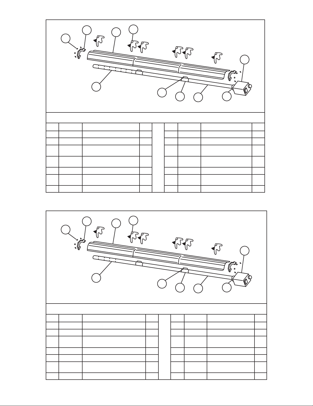
23
INSTRUCTIONS D'UTILISATION ET MANUEL DU PROPRIÉTAIRE
Mr. Heater Series Chauffe-
1
6
2
7
8
4
10
9
3
5
80,000 BTU
Item Stock # Description QTY Item Stock# Description QTY
1 F102652XL 80,000BTULP/BRNet
Boît
1 6 02753
Rebordavant
1
F102653XL 80,000BTUNG/BRNet
Boît
1 7 14 612 Couplagedutube 2
2 F106405XL 80,000BTU,/
Ensembledetubede
6m(20pi)
1 8 14 616
Clépourlecouplagedutube
2
06413
TubeH.E.DE10cm(4po)x3m
(10pi)
3 9 00 419
Emboutduréflecteur
2
3 00418A
Réflecteur
3 10 09369
Pincesàressort
8
4 03445
Déflecteurdeturbulateurde3m
(10pi)
1
5 14585P Support 6
1
6
2
7
8
4
10
9
3
5
100,000 BTU
Item Stock # Description QTY Item Stock# Description QTY
1 F102654XL 100,000BTUNG/BRNet
Boît
1 6 02753
Rebordavant
1
F102655XL 100,000BTULP/BRNet
Boît
1 7 14 612
Couplagedutube
2
2 F106401XL 100,000BTU/TubeSet-30'
Ensembledetubede9.1m(30pi)
1 8 14 616
Clépourlecouplagedutube
2
06413
TubeH.E.DE10cm(4po)x3m(10pi)
3 9 00 419
Emboutduréflecteur
2
3 00418A
Réflecteur
3 10 09369
Pincesàressort
8
4 03447
Déflecteurdeturbulateurde1.5m
(10pi)
1
5 14585P
Support
4
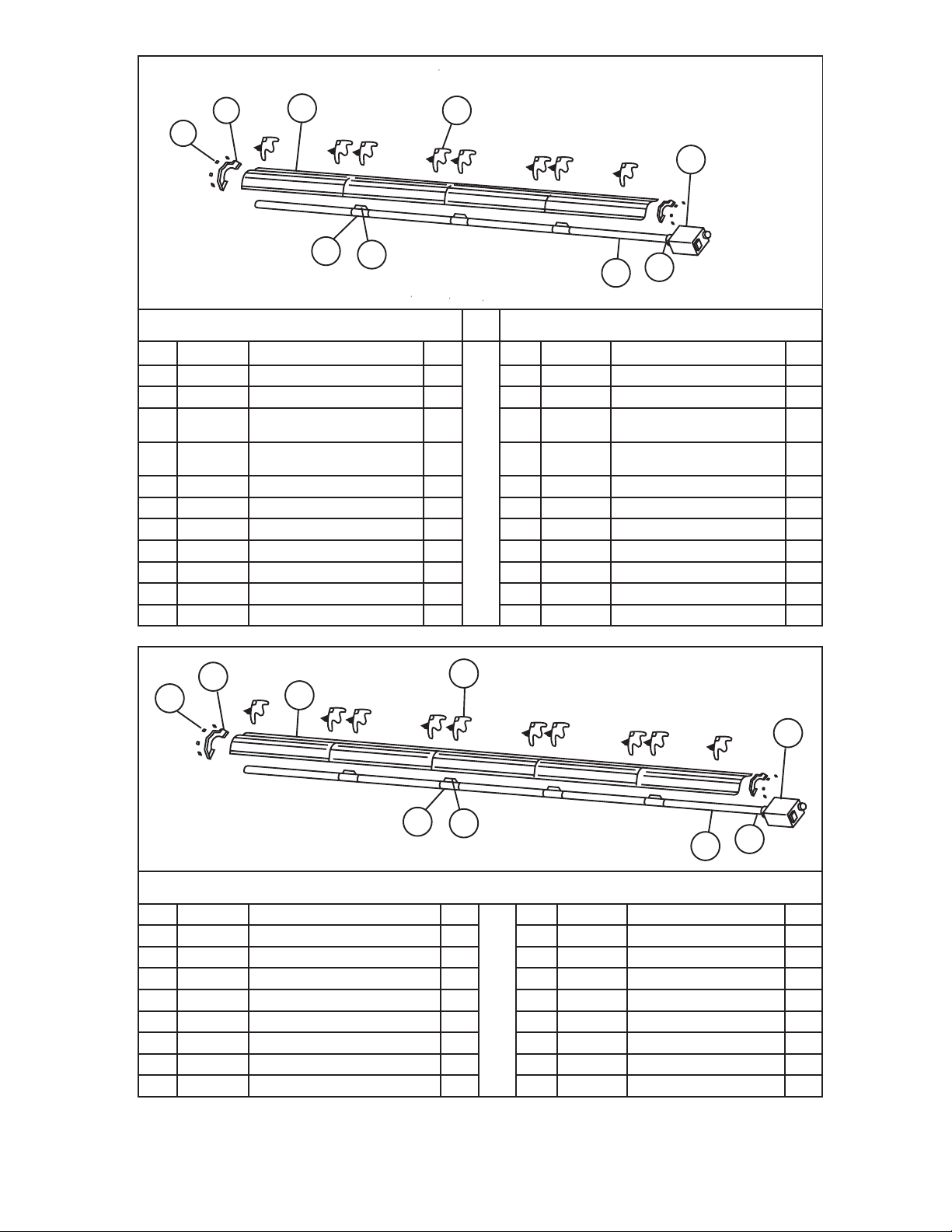
24
Mr. Heater Series Chauffe-
INSTRUCTIONS D'UTILISATION ET MANUEL DU PROPRIÉTAIRE
100,000 BTU
125,000 BTU
Item Stock # Description QTY Item Stock# Description QTY
1 F102654XL 100,000BTUNG/BRNet
Boît
1 1 F102656XL 125,000BTUNG/BRNet
Boît
1
F102655XL 100,000BTULP/BRNet
Boît
1 F102657XL 125,000BTULP/BRNet
Boît
1
2 F106406XL 100,000BTU/
Ensembledetube
de12.1m(40pi)
1 2 F106406XL 125,000BTU/
Ensembledetubede
12.1m(40pi)
1
06413
TubeH.E.DE10cm(4po)x3m
(10pi)
4 06413
TubeH.E.DE10cm(4po)x3m
(10pi)
4
6 02753
Rebordavant
1 3 02753
Rebordavant
1
4 14 612 Couplagedutube 1 4 14 612 Couplagedutube 1
5 14 616
Clépourlecouplagedutube
1 5 14 616
Clépourlecouplagedutube
1
6 00418A
Réflecteur
4 6 00418A
Réflecteur
4
7 14585P
Support
8 7 14585P Support 8
8 0 0 419
Emboutduréflecteur
2 8 00 419
Emboutduréflecteur
2
9 09369
Pincesàressort
8 9 09369
Pincesàressort
8
8
9
6
7
1
3
2
4
5
125,000 BTU / 150,000 BTU / 175,000 BTU
Item Stock # Description QTY Item Stock# Description QTY
1 F102656XL 125,000BTUNG/BRNet
Boît
1 3 02753
Rebordavant
1
1 F102657XL 125,000BTULP/BRNet
Boît
1 4 14 612 Couplagedutube 2
1 F102658XL 150,000BTUNG/BRNet
Boît
1 5 14 616
Clépourlecouplagedutube
2
1 F102659XL 150,000BTULP/BRNet
Boît
1 6 00418A
Réflecteur
5
1 F102660XL 175,000BTUNG/BRNet
Boît
1 7 14585 Support 10
1 F102661XL 175,000BTULP/BRNet
Boît
1 8 00 419
Emboutduréflecteur
2
2 F106407XL
Ensembledetubede15.2m(50pi)
1 9 09369
Pincesàressort
8
06413
TubeH.E.DE10cm(4po)x3m(10pi)
3
1
3
2
7
5
4
6
9
8
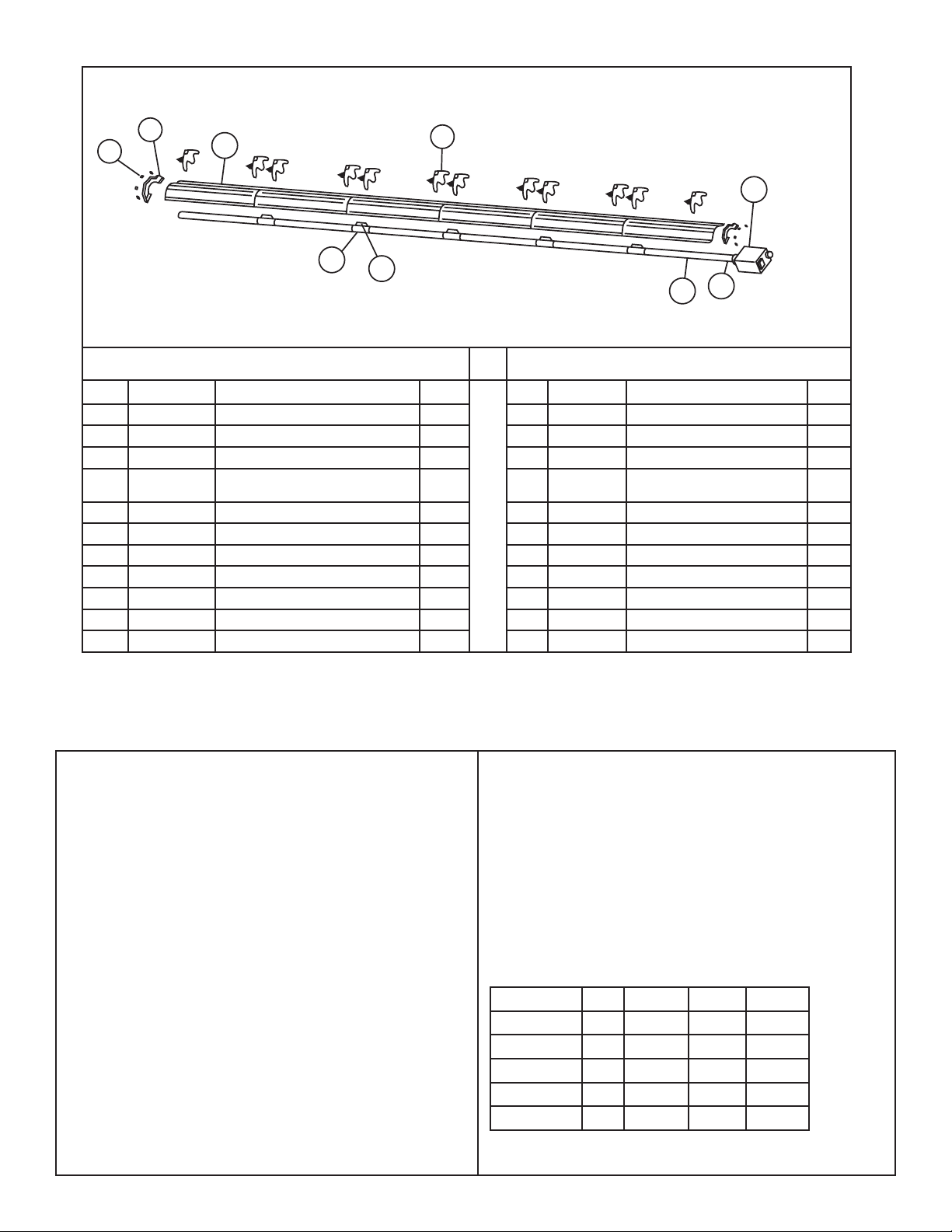
25
INSTRUCTIONS D'UTILISATION ET MANUEL DU PROPRIÉTAIRE
Mr. Heater Series Chauffe-
1
2
3
7
6
4
5
9
8
150,000 BTU 175,000 BTU
Item Stock # Description QTY Item Stock# Description QTY
1 F102658XL 150,000BTUNG/BRNet
Boît
1 1 F102660XL 175,000BTUNG/BRNet
Boît
1
1 F102659XL 150,000BTULP/BRNet
Boît
1 1 F102661XL 175,000BTULP/BRNet
Boît
1
2 F106403XL
Ensembledetubede18.2m(60pi)
1 2 F106403XL
Ensembledetubede18.2m(60pi)
1
06413
TubeH.E.DE10cm(4po)x3m(10pi)
6 06413
TubeH.E.DE10cm(4po)x3m
(10pi)
6
3 02753
Rebordavant
1 3 02753
Rebordavant
1
4 14 612 Couplagedutube 5 4 14 612 Couplagedutube 5
5 14 616
Clépourlecouplagedutube
5 5 14 616
Clépourlecouplagedutube
5
6 00418A
Réflecteur
6 6 00418A
Réflecteur
6
7 14585P Support 12 7 14585P Support 12
8 0 0 419
Emboutduréflecteur
2 8 00 419
Emboutduréflecteur
2
9 09369
Pincesàressort
8 9 09369
Pincesàressort
8
Stock Number Description
10371................................... Thermostat24volt
10392................................... Thermostat110Volt
17370................................... Ensembledechaîne
16401.................................. Flexibleenacierinoxydablede24po
16405..................................
Acierinoxidablede1/2pox24po3/4po
F106414...............................
Ensembled'accessoiresdutubeenU180°
F106415............................... Ensembled'accessoiresducoude90
19021 ................................... VentAdaptor
06430.................................. Capuchond'aération
00438.................................. Ensemblederéflecteurlatéral
01376 ................................... KITDÉFLECTEUR(5')
19031 ................................... Tendeur5/16po-18po
INSTALLATION KITS
F111751…………Installationkitfor20’tubeheater
F111752…………Installationkitfor30’tubeheater
F111753…………Installationkitfor40’tubeheater
F111754…………Installationkitfor50’tubeheater
F111755…………Installationkitfor60’tubeheater
Kitd'installationcomprend:
24voltsthermostat,chapeaudecheminée,24"connecteursenacier
inoxydableflexibledegaz,vanned'arrêtdugaz,etdelachaînede
kitsnécessairespouraccrocherchauffe.
CONVERSION KITS
60,000 BTU
11732 LPTONG 117 33 NGTOLP
80,000 BTU
1173 4 LPTONG 117 3 5 NGTOLP
100,000 BTU
1173 6 LPTONG 117 37 NGTOLP
125,000 BTU
1173 8 LPTONG 117 3 9 NGTOLP
150,000 BTU
1174 0 LPTONG 11741 NGTOLP
175,000 BTU
1173 0 LPTONG 117 31 NGTOLP
ACCESSOIRES
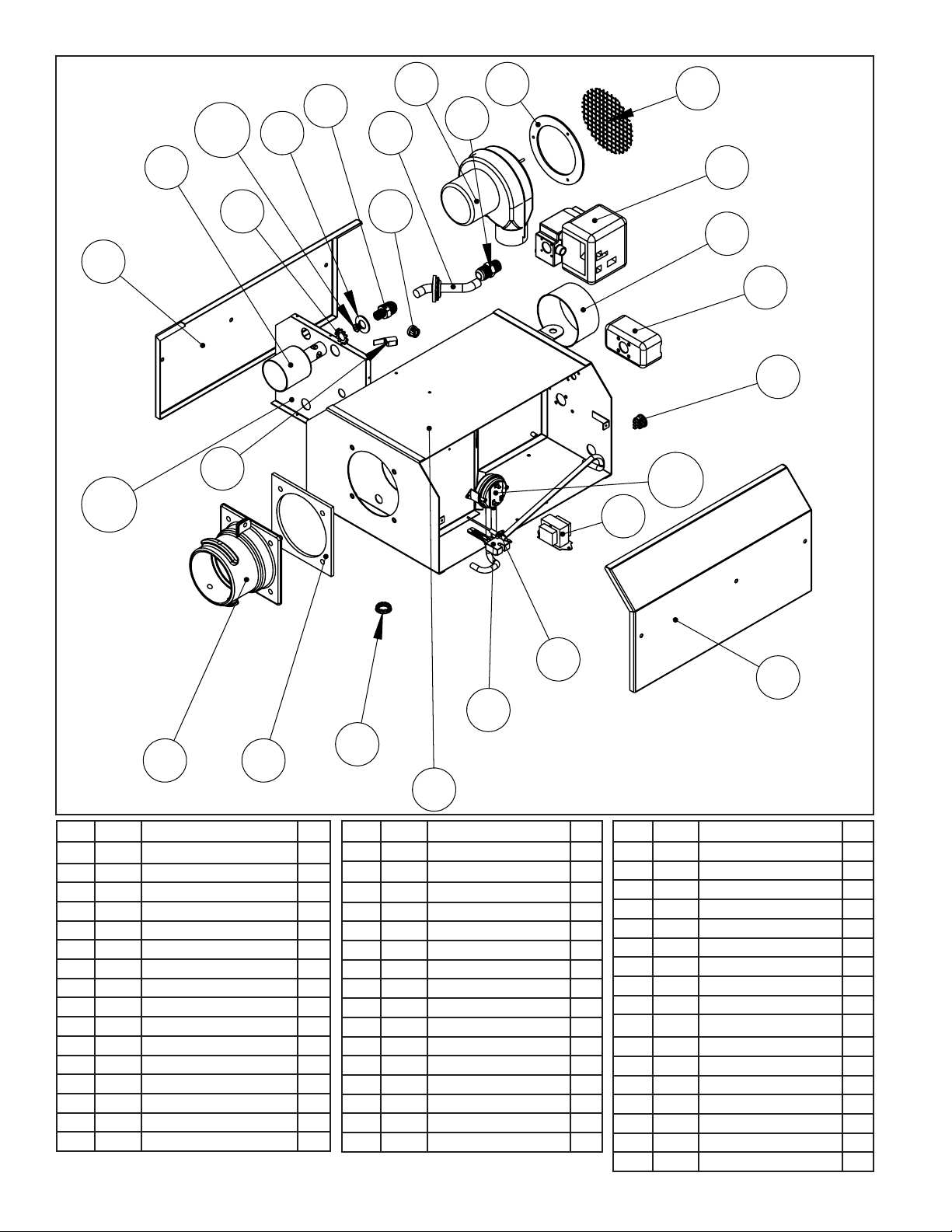
26
Mr. Heater Series Chauffe-
INSTRUCTIONS D'UTILISATION ET MANUEL DU PROPRIÉTAIRE
1
2
3
6
5
4
ITEM# EGI # DESCRIPTION QTY
17 05502XL 80KPLAQUED'AIR 1
18 05501XL 100KPLAQUED'AIR 1
19 05500XL 125KPLAQUED'AIR 1
20 05503XL 150KPLAQUED'AIR 1
21 05508XL 175KPLAQUED'AIR 1
22A 00016
SOUPAPEÀGAZ(NG)
1
22B 00017
SOUPAPEÀGAZ(LP)
1
23 0275 8
RACCORDDELASORTIEDELASOUPAPEÀGA
1
24 17379
COLLECTEURDEGAZ
1
25 02720
SUPPORTD'ORIFICE
1
26 98541
RONDELLEPLATEDUSUPPORTD'ORIFICE
1
27 05794
40KORIFICE(NG)
1
28 05749
40KORIFICE(LP)
1
29 05726
60KORIFICE(NG)
1
30 05744
60KORIFICE(LP)
1
31 05718
80KORIFICE(NG)
1
ITEM# EGI # DESCRIPTION QTY
32 05737
80KORIFICE(LP)
1
33 0 5712
100KORIFICE(NG)
1
34 05733
100KORIFICE(LP)
1
35 05703
125KORIFICE(NG)
1
36 05730
125KORIFICE(LP)
1
37 05796
150KORIFICE(NG)
1
38 05728
150KORIFICE(LP)
1
39 05799
175ORIFICE(NG)
1
40 05725
175KORIFICE(LP)
1
41 98547
RONDELLEDENTÉEEXTERNE
1
42 02371
GOBELETDUBRÛLEUR
1
43 10391A
INTERRUPTEURDELAPORTE
1
44 02721
BAGUEÀ2EXTRÉMITÉS
1
45 07376
VENTILATEUR
1
46 12395
RONDELLEDUVENTILATEUR
1
47 02718
ÉCRANDUVENTILATEUR
1
48 02795
FENÊTREDEVUE
1
ITEM# EGI # DESCRIPTION QTY
1 02716XL
ENCEINTE
1
2 02725XL
COUVERCLELATÉRALDESCOMMANDES
1
3 02749XL
COUVERCLELATÉRALDUMOTEUR
1
4 12397
JOINTD'ÉTANCHÉITÉDUREBORDAVANT
1
5 02753
REBORDDUTUBEAVANT
1
6 08364A
MODULED'ALLUMAGE
1
7 02836
TRANSFORMATEUR
1
8 10 413 A
MANOSTAT125/80ET100/60
1
9 10 414A
MANOSTAT175/125
1
10 02730
ALLUMEURDESURFACECHAUDE
1
11 02765
TIGEDEDÉTECTEURDEFLAMME
1
12 02847
BAGUEÀ3EXTRÉMITÉSDETHERMOSTAT
1
13 99101
BOÎTEDEJONCTIONÉLECTRIQUE
1
14 02747
REBORDDEPRISEDUVENTILATEUR
1
15 05510XL
40KPLAQUED'AIR
1
16 06606XL
60KPLAQUED'AIR
1
40
41
42
43
44
45 46
47
48
7-9
10
11
12
13
14
15-
21
22
23
24
25
26
27-

27
INSTRUCTIONS D'UTILISATION ET MANUEL DU PROPRIÉTAIRE
Mr. Heater Series Chauffe-
REMARQUES:
28
Mr. Heater Series Chauffe-
INSTRUCTIONS D'UTILISATION ET MANUEL DU PROPRIÉTAIRE
AVERTISSEMENT :
N’UTILISEZQUELESPIÈCESDEREMPLACEMENTDUFABRICANT.L’UTILISATION
D’AUTRESPIÈCESRISQUEDECAUSERDESBLESSURESETLAMORT.LESPIÈCESDE
REMPLACEMENTNESONTOFFERTESQUEPARLEFABRICANTETDOIVENTÊTRE
INSTALLÉESPARUNEENTREPRISEDESERVICESPÉCIALISÉE.
POUR OBTENIR DES INFORMATIONS SUR LE SERVICE OU LES PIÈCES :
Contactezvotrefournisseuroutechniciendeservicedechauffagelocal.
POUR TOUTE INFORMATION SUPPLÉMENTAIRE :
Veuillezappelerlalignesansfrais800251-0001•www.Mr.Heaterbyenerco.com
Nosheuresdebureausontde8hà17h,HNE,dulundiauvendredi.
Veuillezavoirlenumérodumodèle,lenumérodesérieetladated'achatàportéede
main.
GARANTI LIMITÉE
L'entreprisegarantiequeceproduitestexemptd'imperfectionsdanslematérieloulamain-d'œuvre,sous
uneutilisationnormaleetadéquateselonlesdirectivesdel'entreprise,pourunepériodede10añosapartir
delafechadeentregaalcompradorconlassiguientesexcepciones.
•Pourl'installationdansunlave-autoetdansleszonesàl'expositionàdesproduitschimiquescorrosifs,
telsquel'ammoniac,lechlore,etc.,lagarantieseralimitéeà2anssurlestubeset1ansurlesautres
composantes.
L'entreprise,àsonoption,répareraouremplaceralesproduitsretournésparl'acheteuràl'usine,letransport
prépayéàl'intérieurdeladitepérioded'unan,ettrouvésparl'entreprisecommeayantdesimperfections
danslematériauoulamain-d'œuvre.
Siunepièceestendommagéeoumanquante,appeleznotreServicedesoutientechnique
au800251-0001.
Envoyeztouteréclamationdegarantieauserviceàlaclientèle,Mr.Heater,Inc,4560W.160THST.,
CLEVELAND,OHIO44135États-Unis.Incluezvotrenom,adresseetnumérodetéléphoneainsiquelesdétails
concernantlarevendication.Deplus,fournissez-nousladated'achatetlenometl'adressedufournisseurde
quivousavezacheténotreproduit.
Cequiprécèdeestlapleineétenduedelaresponsabilitédel'entreprise.Iln'existeaucuneautregarantie,
expresseouimplicite.Spécifiquement,iln'existeaucunegarantied'adaptabilitéàunefinenparticulieret
aucunegarantiedemarchandabilité.Enaucuncasl'entreprisedoitêtreresponsabledesdélaisprovoqués
parlesimperfections,desdommagesdeconséquenceoupourtoutfraisdesdépensesdequelquenature
encouruessanssonconsentementparécrit.Lecoûtdelaréparationouduremplacementdoitêtrela
solutionexclusivepourtoutbrisdelagarantie.Iln'existeaucunegarantiecontrelenon-respectdecelle-ciet
aucunegarantieimplicitedécoulantducoursdelatransactionoudel'usagecommercial.Cettegarantiene
s'appliquerapasàtoutproduitquiaétéréparéoumodifiéhorsdel'usinedequelquefaçonqui,selonnous,
affectesaconditionousonopération.
CertainsÉtatsoucertainesprovincesn'autorisentnil'exclusionnilarestrictiondesdommagesaccessoires
ouconsécutifs,parconséquent,lesrestrictionsouexclusionsprécédentespeuventnepass'appliqueràvotre
cas.Laprésentegarantievousdonnedesgarantiesjuridiquesparticulièresetvouspouvezégalementjouir
d’autresdroitsquivarientd’uneprovinceoud’unÉtatàl’autre.
Mr.Heater,Inc,4560W.160THST.,CLEVELAND,OHIO44135•866-447-2194
©2016,Mr.Heater,IncTousdroitsréservés
Mr.Heater,Incseréserveledroitdemodifierentouttemps,sanspréavisniobligation,lescouleurs,
spécifications,accessoires,matériauxetmodèles.
INSTRUCTIONS D'UTILISATION ET MANUEL DU PROPRIÉTAIRE
ANSI Z83.20b-2011 CSA 2.34b-2011
C
US
110VMODELS
40,000BTU60,000BTU
80,000BTU 100,000BTU
125,000BTU150,000BTU
175,000BTU
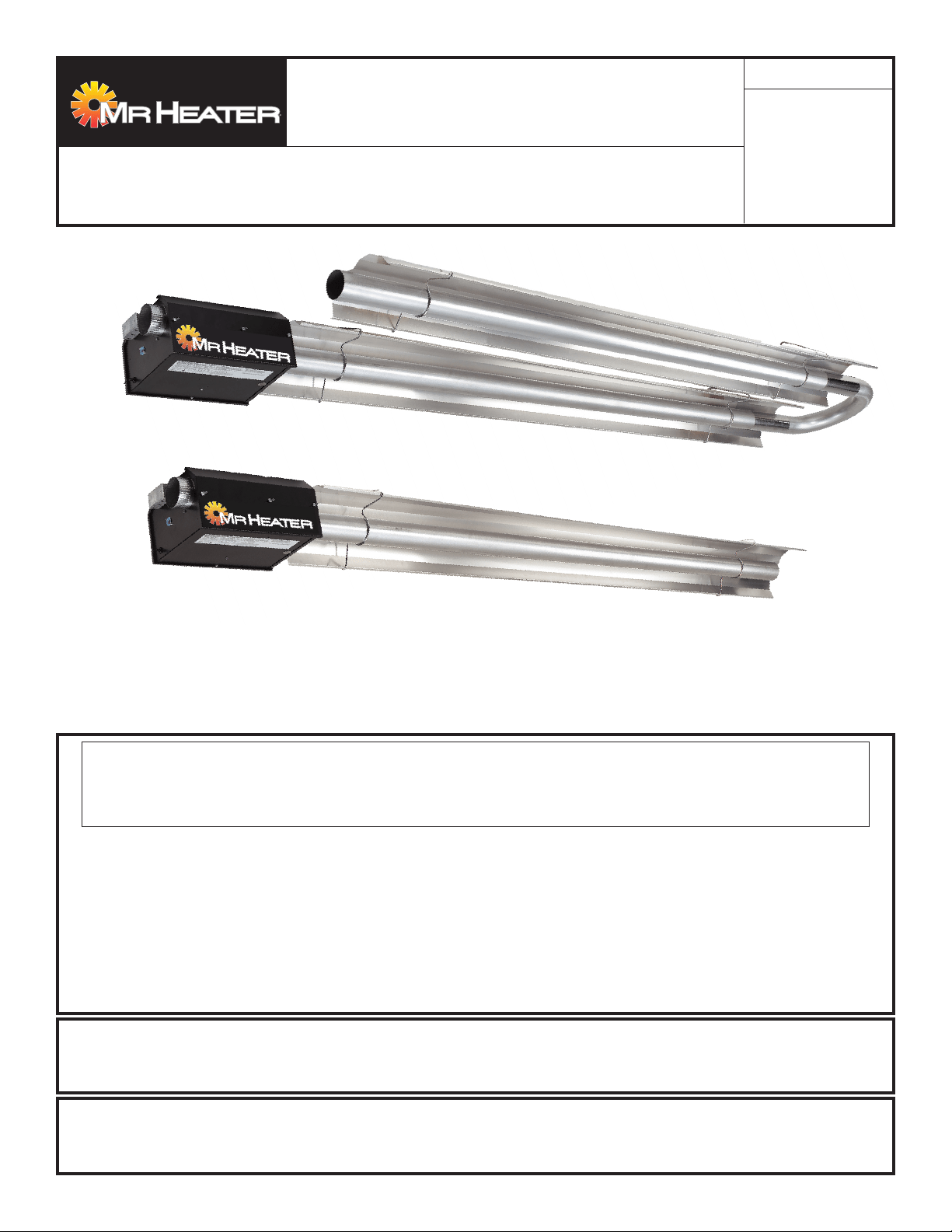
— QUÉHACERSIDETECTAOLORAGAS
•Abrirlasventanas
•NOintentarencenderningúnartefacto.
•NOutilizarningúninterruptoreléctrico.
• NO
usarningúnteléfonoensucasa.Llameinmediatamentealacompañíalocaldegasdesdeelteléfonodeunvecino
.
Sigalasinstruccionesdelacompañíadegas.
• No toque ningúninterruptoreléctrico;nouseningúnteléfonoeneledificio.
•
Lainstalaciónylareparacióndebenserrealizadasporuninstaladorcalificado,agenciadereparacionesolacompañíadegas.
•Sinosepuedecomunicarconlacompañíadegas,llamealosbomberos.
POR SU SEGURIDAD:
Noalmaceneniutilicegasolinaniningúnotrovapornilíquidoinflamablecercadeestenideningúnotroartefacto.
ADVERTENCIA: Sinosesiguenestasinstruccionesalpiedelaletra,podríaproducirseunincendioounaexplosión
queprovocaríadañosmateriales,lesionesomuertes.
18677XL2016CB
Mr.Heater,Inc.,4560W.160THST.,CLEVELAND,OHIO44135•866-447-2194
ADVERTENCIA: La instalación, ajuste, alteración, reparación o mantenimiento inadecuados
puede causar daños materiales, lesiones o la muerte. Lea completamente las instrucciones de
instalación, operación y mantenimiento antes de instalar o reparar este equipo.
IDIOMAS INCLUIDOS
•INGLÉS
•FRANCÉS
•ESPAÑOL
MR. Heater Calefactores infrarrojos a
gas, de baja intensidad, aprobados para aplicaciones
comerciales
INSTRUCCIONES DE USO Y
MANUAL DEL USUARIO
LEA CUIDADOSAMENTE LAS INSTRUCCIONES:Leaysigatodaslasinstrucciones.
Conserveestasinstruccionesenunlugarseguroparafuturareferencia.Nopermitaque
nadiequenohayaleídoestasinstruccionesarme,encienda,ajusteouseelcalentador.
Modelo#
40,000BTU60,000BTU
80,000BTU100,000BTU
125,000BTU150,000BTU
175,000BTU
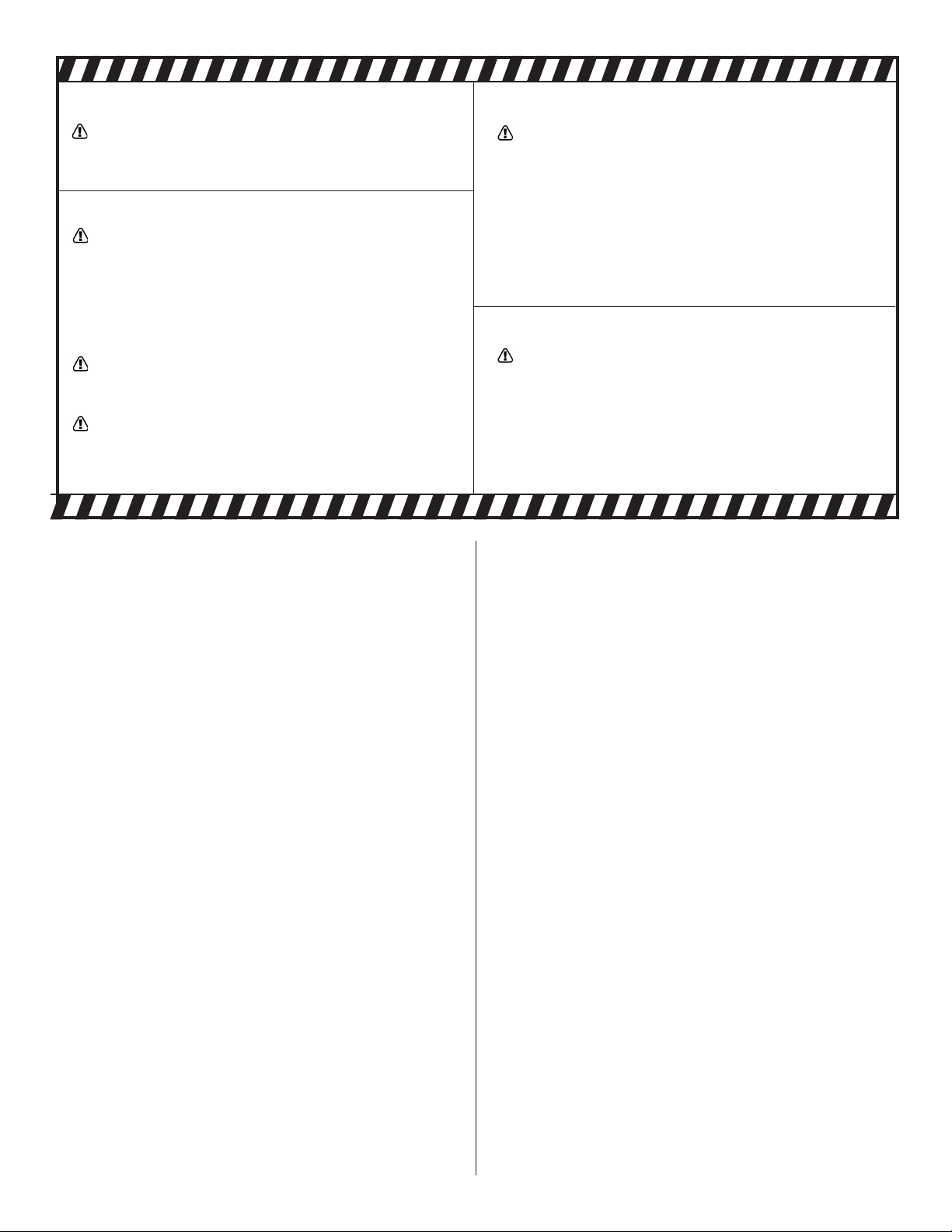
2
Enerco | Calefactor Heatstar ERXL Serie Tubor Instrucciones de uso y manual del usuario
SECTION 1:Introduction
LosmodelosMr.Heateroncalefactoresinfrarrojoseconómicos,
dearmadoenellugar,quesonfácilesdeinstalaryque
requierenmuypocomantenimiento.Estándiseñadospara
brindarañosdefuncionamientoeconómicosinproblemas.
Verificación del envío
Compareelenvíocontralalistadeenvíoparaverificarque
nolefaltenada.Además,reviselascajasparaverificarqueno
tengandañosexternos.Anotecualquiercosaquefaltey/olos
dañosexternosalascajasenlalistadeenvíoantelapresencia
delcamioneroquerealizalaentrega.Elcamionerodeberá
reconocercualquierfaltanteodañocolocandosusinicialesen
lalistadeenvíoconloscomentarios.Realiceinmediatamente
elreclamopormaterialesdañadosofaltantesquenohaya
notadoalmomentoderecibirlos,alaempresadetransportey
alrepresentantedelafábricaMr.Heater,Inc.
Installer Responsibility
Todosloscalefactoresylastuberíasdegasasociadasdebenser
instaladasdeacuerdoconlasespecificacionescorrespondientes
ylainstalacióndebeserrealizadaúnicamenteporempresas(o
personas)correctamentecalificadasparaestetipodetrabajo.
Consulteconinspectoreslocalesdeedificios,losbomberos
osurepresentantelocaldelafábricaMr.Heater,Incpor
recomendaciones.
LainstalacióndeloscalefactoresMr.Heatersebasaenla
informaciónsuministradaenundiagramadedistribución,
quejuntoconlasnormasyreglamentacionesmencionadas
anteriormenteconstituyenlainformaciónbásicanecesariapara
completarlainstalación.Elinstaladordeberáproporcionar
todoelmaterialnecesarioquenoseincluyecomoequipo
estándar,yessuresponsabilidadverificarquedichomaterialy
losmétodosdeinstalaciónqueutiliceconstituyanuntrabajo
decalidadprofesionalydeacuerdocontodaslasnormas
correspondientes.
LosrepresentantesdeMr.Heater,Inccuentancon
entrenamientoyexperienciaenesteequipoylospuedellamar
porsugerenciasacercadelainstalación,loquepuedeahorrarle
materialydinero.
ADVERTENCIA:
PELIGRODEINCENDIO,QUEMADURAS,INHALACIÓN
YEXPLOSIÓN.MANTENGALOSCOMBUSTIBLES
SÓLIDOSCOMOMATERIALESDECONSTRUCCIÓN,
PAPELOCARTÓNAUNADISTANCIASEGURADEL
CALEFACTORTALCOMOLORECOMIENDANLAS
INSTRUCCIONES.NUNCAUSEELCALENTADOREN
ESPACIOSQUECONTIENENOPODRÍANCONTENER
COMBUSTIBLESVOLÁTILESOPRODUCTOSCOMO
GASOLINA,SOLVENTES,DILUYENTEDEPINTURAO
PRODUCTOSQUÍMICOSDESCONOCIDOS.
ADVERTENCIA GENERAL DE PELIGRO:
ELNOCUMPLIRCONLASPRECAUCIONESE
INSTRUCCIONESQUEVIENENCONESTECALENTADOR
PUEDECAUSARLAMUERTE,LESIONESGRAVESY
PÉRDIDASYDAÑOSMATERIALESDERIVADOSDEL
PELIGRODEINCENDIO,EXPLOSIÓN,QUEMADURAS,
ASFIXIA,ENVENENAMIENTOCONMONÓXIDODE
CARBONO,Y/ODESCARGASELÉCTRICAS.
SOLOLASPERSONASQUEENTIENDANYPUEDANSE-
GUIRLASINSTRUCCIONESDEBENUSAROMANTENER
ESTECALENTADOR.
SINECESITAAYUDAOINFORMACIÓNACERCADEL
CALENTADOR,COMOUNMANUALDEINSTRUCCIO-
NES,ETIQUETAS,ETC.,PÓNGASEENCONTACTOCON
ELFABRICANTE.
ADVERTENCIA:
SUSEGURIDADESIMPORTANTEPARAUSTEDY
PARALOSDEMÁS,ASÍQUEPORFAVORLEAESTAS
INSTRUCCIONESANTESDEUTILIZARELCALENTADOR.
CONTENTS
Sección1INTRODUCCIÓN.........................................................2
Section2PLANNING.................................................................3
Sección3INSTALACIÓNYARMADO.......................................6
Sección4ESPECIFICACIONESDEINGENIERÍA.........................13
Sección 5 VENTEO/CONDUCTOS ……………………………………14
Sección6TUBERÍADEGAS............................................................17
Sección7CABLEADO...................................................................18
Sección8OPERACIÓNYMANTENIMIENTO....................................19
Sección8RESOLUCIÓNDEPROBLEMAS………………………………21
Sección9PARTESDEREPUESTO..............................................22
INFORMACIÓNDEGARANTÍA.....................................................28
ADVERTENCIA:
El estado de California requiere la siguiente advertencia:
UNADELASSUSTANCIASQUESEDESPRENDEENLA
COMBUSTIÓNALUSARESTEEQUIPOESELMONÓXIDO
DECARBONO,UNPRODUCTOQUÍMICOQUEDE
ACUERDOCONELESTADODECALIFORNIAPRODUCE
CÁNCERYDEFECTOSDENACIMIENTO(UOTROS
DAÑOSREPRODUCTIVOS).

3
Instrucciones de uso y manual del usuarioEnerco | Calefactor Heatstar ERXL Serie Tubor
SECCIÓN 2: Planificación
Debenrespetarselassiguientesnormaseinstruccionesal
planificarlainstalacióndelcalefactorEner-RadiantER2STG.
Ademásdeestasinstrucciones,hayquerespetarcuidadosamente
lasadvertenciasdelaSección1,yaqueunainstalación
inadecuadapodríacausardañosmateriales,lesionesolamuerte.
Normas nacionales y
reglamentaciones correspondientes
Normas de gas:
Sedebeutilizareltipodegasqueseindicaenlaplacade
identificación.Lainstalacióndebecumplirconlasnormas
locales,conlasrecomendacionesdelacompañíalocaldegas
yconelCódigonacionaldelgascombustible,ANSIZ223.1
–últimaversión,(igualqueconelBoletínNFPA54)oconel
Códigodeinstalacióndegasnaturalypropano,CSAB149.1.
• Debemantenerselaseparaciónentreelcalefactorysuventila-
ciónyelmaterialcombustibleadyacente(yaseapartedeledi-
ficioosucontenido)paracumplirconlanormadeinstalación
deartefactosagasytuberíasdegas,NFPA-54/ANSIZ223.1
–últimaversión,elCódigonacionaldelgascombustibleoel
Códigodeinstalacióndegasnaturalypropano,CSAB149.1.
Hangares para aviones:
Lainstalaciónenhangaresdeavionesdebehacersede
acuerdoconlaNormaparahangaresdeaviones,ANSI/
NFPA-409–últimaversión.
•Enlugaresdealmacenamientooreparacióndeaviones,los
calefactoresdebeninstalarseaunaalturade3mporencima
delasuperficiesuperiordelasalasodeloscompartimientos
demotoresdelaviónmásaltoquepodríaguardarseenel
hangar.(Estodebemedirsedesdelapartedeabajodel
calefactorhastaelalaoelcompartimientodelmotor,loque
seamásaltodesdeelpiso).
•Enotrasseccionesdehangaresparaaviones,comotalleresu
oficinas,nosepuedeninstalarcalefactoresamenosde2,5m
dealtura.
•Loscalefactoresinstaladosenhangaresparaavionesdeben
ubicarsedemaneraquenoseandañadosporlosaviones,
grúas,andamiosmóvilesuotrosobjetos.
Estacionamientos públicos:
Lainstalaciónenestacionamientosdebehacersedeacuerdo
conlaNormaparaestructurasdeestacionamientos,
NFPA-88A–últimaversiónolaNormaparatalleresde
reparaciones,NFPA-88B–últimaversión.
•Nosepuedeninstalarloscalefactoresamenosde2,5mde
altura.Sedebenmantenerlasdistanciasmínimasacombusti-
blesparalosvehículosestacionadosdebajodelcalefactor.
•Cuandoseinstalansobreaparejoselevadores,sedebenman-
tenerlasdistanciasmínimasacombustiblesdesdeelpunto
másaltodelelevador.
Venteo:
Elventeodebeinstalarsedeacuerdoconlaúltimaversiónde
ANSIZ223.1oCSA149.1.Sesuministrainformaciónparcial
acercadeestanormaenlaSección5deestemanualdeins-
talación,conrespectoaltamañoyconfiguracióndesistemas
deventeo.
•Todaseccióndelastuberíaspresurizadasquepasenatravés
deunaparedcombustibledebenestardoblementeaisladaso
tenerunguardacaboaprobado.Consultelaúltimaversiónde
ANSIZ223.1oCSA149.1.
Lugares peligrosos:
Cuandoexistalaposibilidaddeexposiciónamaterial
combustiblesuspendidoenelaireoenformadevapor,
consulteconlosbomberoslocales,lacompañíadeseguros
contraincendiouotrasautoridadesparaqueapruebenla
instalaciónpropuesta.
Consideraciones críticas
ElMr.Heateresuncalefactorsuspendido.Porlotanto,su
estabilidad,flexibilidadyseguridadsonmuyimportantes.
Antesdecomenzarconlainstalación,verifiquequeelsistema
puedacumplirconlossiguientesrequisitos.
•Mantenerlasdistanciasespecificadasacombustiblesyuna
distanciaseguraamateriales,equiposyestacionesdetrabajo
sensiblesalcalor.
•Lasdistanciasacombustiblesindicadasrepresentanuna
temperaturasuperficialde90°F(30°C)porencimadela
temperaturaambiente.Losmaterialesdeconstruccióncon
bajatoleranciaalatemperatura(comoelplástico,revesti-
mientovinílico,lona,etc.)podríandegradarseatemperaturas
menores.Esresponsabilidaddelinstaladorelasegurarseque
losmaterialesadyacentesesténprotegidoscontraladegrada-
ción.
•Proporcionarunasuspensiónconuntramoverticaldecadena
ovarillaquetengaporlomenos2"demovimientohorizontal
enlínearectaparacadaquemador.Asegúresedequeelsis-
temadesuspensiónsealosuficientementeflexiblecomopara
permitirlaexpansióntérmicaqueocurrecuandoelsistemase
calienta(verlaFigura6delapágina11).
•Brindaraccesoalosquemadoresparareparaciones,prefe-
rentementedeamboslados,porencimaypordebajodel
quemadorparapoderremoverlo.
•Brindarunaseparaciónmínimade18pulgadasentreel
quemadorylasparedesdeledificio.(Respetarsiemprelas
distanciasmínimasamaterialescombustibles).
•Asegúresedequeelcalefactortengaunainclinaciónde1/2
pulgadaporcada20piesdedistanciadelquemador.
•Proporcionarcartelesenlugaresdealmacenamientoespe-
cificandolaalturamáximadeapilamientorequeridapara
mantenerlasdistanciasrequeridasamaterialescombustibles.
•Planearlossoportesparaellugar(verlaFigura2A-Ddela
página8).Colocarunsoportecercadetodosloscodos.
•Lainstalacióndebecumplirconlasnormaslocalesde
construcción,ysinoexistennormaslocales,conelCódigo
nacionaldelgascombustible,ANSIZ223.1/NFPA54oconel
Códigodeinstalacióndegasnaturalypropano,CSAB149.1.
•Siseutilizaunafuentedeenergíaeléctricaexterna,elcale-
factor,alinstalarlo,deberáestarconectadoeléctricamente
atierradeacuerdoconlaNormaeléctricanacional,ANSI/
NFPA70oconlaNormadeElectricidadCanadiense,CSA
C22.1.

4
Enerco | Calefactor Heatstar ERXL Serie Tubor Instrucciones de uso y manual del usuario
DISTANCIA A COMBUSTIBLES
TABLA 1: Distancias mínimas a materiales combustibles (use la Figura 1 de la página 5 como guía)
Tipo de
reflector
Posición
40,000
BTU
60,000
BTU
80,000
BTU
100,000
BTU
125,000
BTU
150,000
BTU
175,000
BTU
Reflectorestándar
(horizontal)
A
B
C
D
6”
30”
55”
30”
6”
30”
55”
30”
6”
36”
55”
36”
6”
36”
74”
36”
6”
36”
87”
36”
6”
36”
87”
36”
8”
36”
87”
36”
Reflector
inclinado45°
A
B
C
E
F
12 ”
30”
55”
36”
60”
12 ”
30”
55”
36”
60”
18”
36”
55”
36”
60”
18”
36”
74”
36”
60”
18”
36”
87”
36”
60”
18”
36”
87”
36”
60”
18”
36”
87”
36”
60”
TuboUestándar
(Horizontal)
A
B
C
D
6”
30”
55”
30”
6”
30”
55”
30”
6”
36”
55”
36”
6”
36”
74”
36”
6”
36”
87”
36”
6”
36”
87”
36”
8”
36”
87”
36”
TuboUopuesto
45°
A
B
C
F
12 ”
30”
55”
60”
12 ”
30”
55”
60”
18”
36”
55”
60”
18”
36”
74”
60”
18”
36”
87”
60”
18”
36”
87”
60”
18”
36”
87”
60”
TuboUcompleto
45°
A
B
C
E
F
12 ”
30”
55”
36”
60”
12 ”
30”
55”
36”
60”
18”
36”
55”
36”
60”
18”
36”
74”
36”
60”
18”
36”
87”
36”
60”
18”
36”
87”
36”
60”
18”
36”
87”
36”
60”
Sinventilación AboveA 36” 36” 36” 36” 36” 36” 36”
ADVERTENCIA:
PELIGRO DE INCENDIO Y EXPLOSIÓN
PUEDE CAUSAR DAÑOS MATERIALES, LESIONES GRAVES O LA MUERTE.
Sedebenmantenerlasdistanciasmínimasamaterialescombustiblesentodaslassituaciones.Elnorespetarlasdistanciasmínimasa
materialescombustiblespuedecausardañosmateriales,lesionesgravesolamuerte.
Sedebenmantenerlasdistanciasmínimasparalosvehículosestacionadosdebajodelcalefactor.Sedebencolocarcartelesenlugaresde
almacenamientoespecificandolaalturamáximadeapilamientorequeridaparamantenerlasdistanciasrequeridasamaterialescombustibles.
Hayquetenercuidadoalhacerfuncionarelsistemacercadematerialescombustiblescomomadera,papel,goma,etc.Hayqueteneren
cuentalasparticiones,estantesdealmacenamiento,elevadores,laconstruccióndeledificio,etc.
LaTABLA1indicalasdistanciasmínimasaceptablesamaterialescombustibles.LasdistanciasindicadasenlaTABLA1nosepuedenusaren
lugarescerradosporloscuatrocostados.
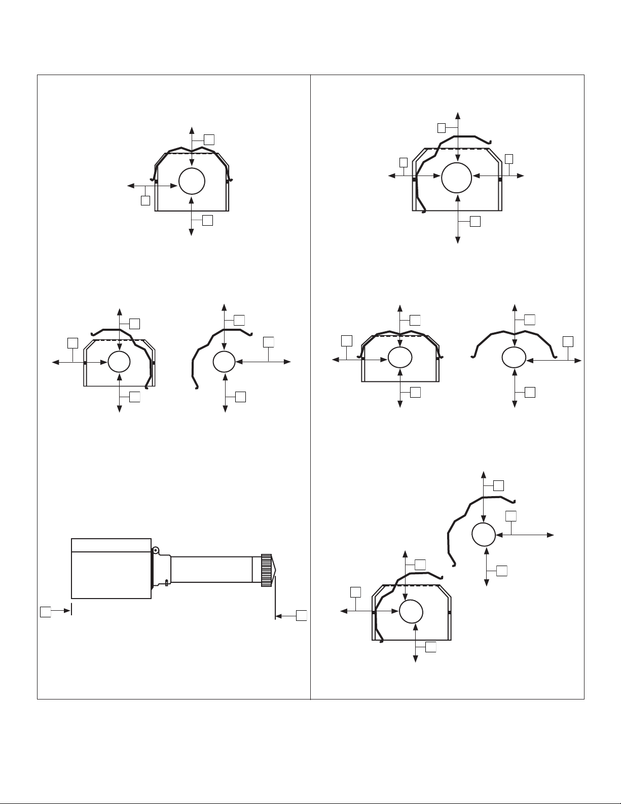
5
Instrucciones de uso y manual del usuarioEnerco | Calefactor Heatstar ERXL Serie Tubor
D
A
C
STANDARD REFLECTOR
A
E
C
E
45 DEGREE REFLECTOR TILT
C
A
EF
U-TUBE OPPOSITE 45 DEGREE
A
C
D
U-TUBE STANDARD
C
E
A
E
U-TUBE FULL 45
B
E
FRONT AND BACK CLEARANCE
Distancias a combustibles
Figura 1: Distanciasacombustibles(consultelaTABLA1delapágina4)
A
C
E
F
D
A
C
A
C
D
A
C
D
F
F
C C
A
A
E
A
F
C
A
C
B
B
REFLECTORESTÁNDAR
TuboU,opuesto45°
Separaciónadelanteyatrás
Reflectorinclinado45°
TuboUestándar
TuboU,completo45°
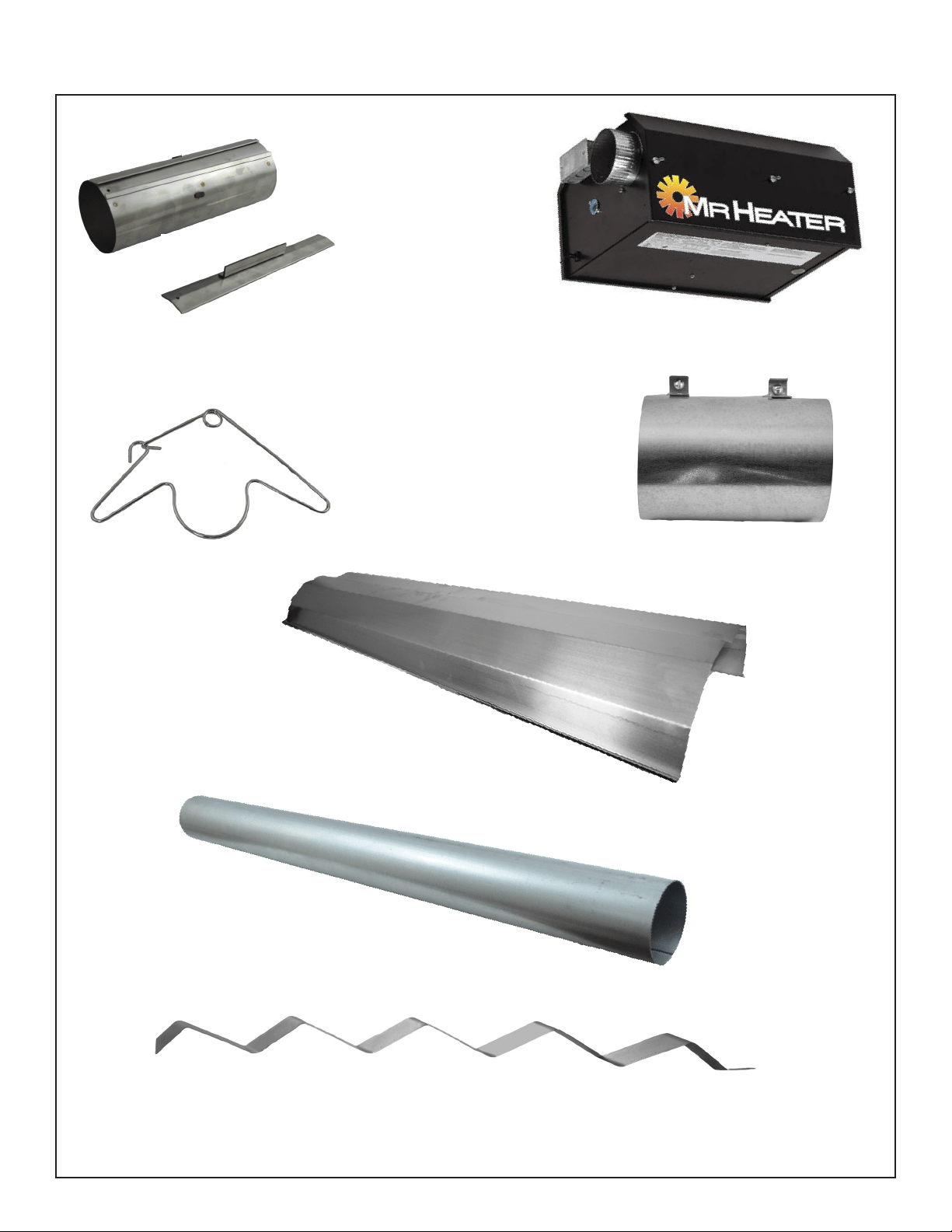
6
Enerco | Calefactor Heatstar ERXL Serie Tubor Instrucciones de uso y manual del usuario
SECTION 3: Installation & Assembly
ACOPLEDETUBERÍA(14612)
ENCASTREPARAELACOPLEDETUBERÍA
(14616)
GANCHO
PARACOLGAR
LATUBERÍA
(14585P)
DEFLECTORDETURBULENCIAS10'(03445)
DEFLECTORDETURBULENCIASDE5'(03447)
**NOVIENEINCLUIDOPARATODOSLOSMODELOS**
**ONLYHEATERS30'LENGTHANDUNDER**
REFLECTOR10'
(00418A)
CAJADEL
QUEMADOR
TUBODE10'DELINTERCAMBIADORDECALOR
(06413)
ADAPTADORDEVENTEO
(19021)
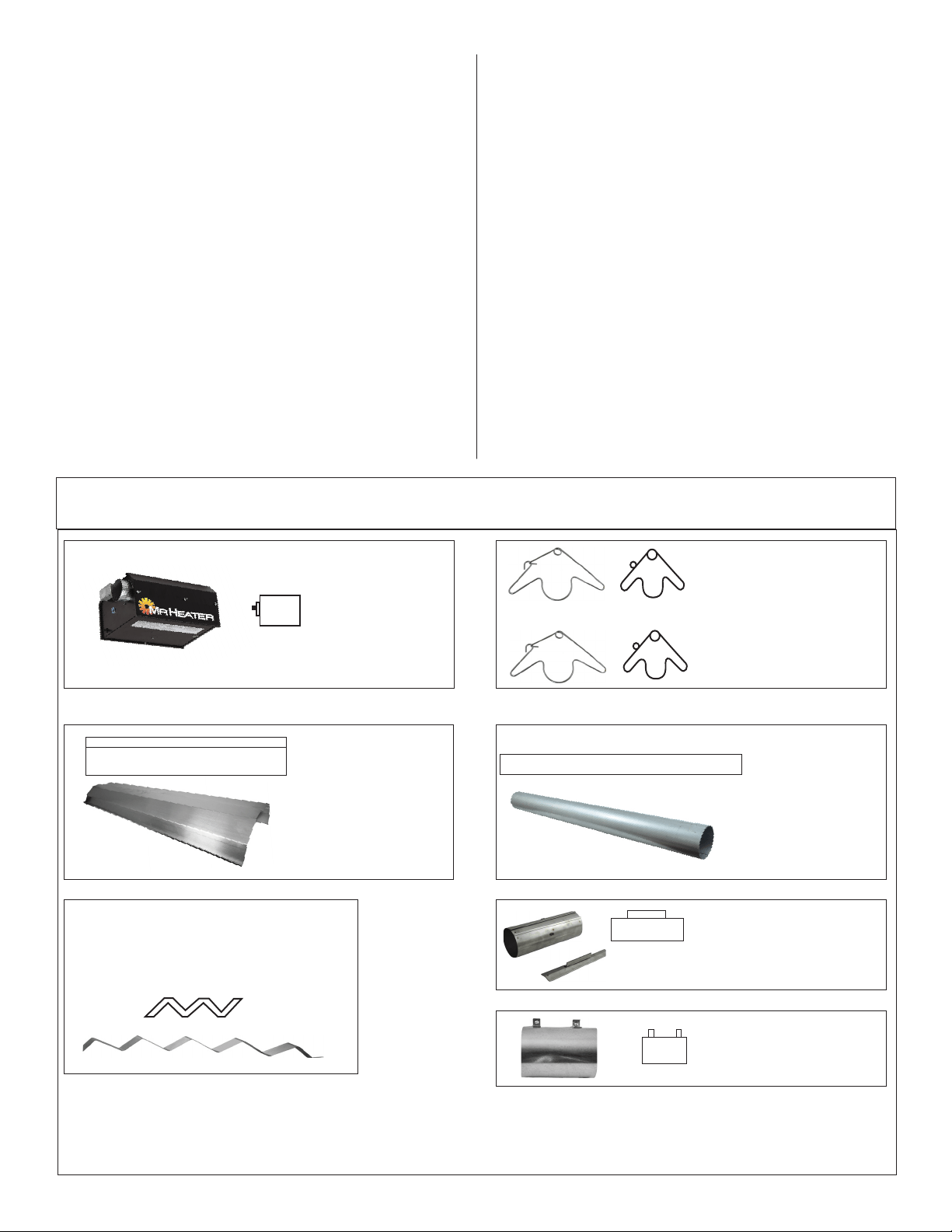
7
Instrucciones de uso y manual del usuarioEnerco | Calefactor Heatstar ERXL Serie Tubor
Procedimiento de instalación
Aprovechealmáximolaestructurasuperiordel
edificio,vigas,viguetas,largueros,etc.dedondepueda
colgarelcalefactor.Noexisteunaúnicasecuenciade
instalaciónparalatubería.Laobservacióndellugar
usualmentelerevelaráunasecuencialógica.Comience
lainstalaciónenellugarcondimensionesmáscríticas.
Estolepodríaahorrartiempo.Fíjeseenlasaperturasde
laspuertas,grúasdeltecho,elevadoresdeautos,etc.
Losdeflectoresylastuberíassepuedenirinstalando
amedidaquevaavanzando.Ajustecuidadosamente
lainclinacióndelsistemaencadaposiciónparanivelar
elcalefactor.Useunainclinaciónhaciaabajodemedia
pulgadaporcada20pies(alejándosedelquemador).
NO HACER
Probarlatuberíadegasconaltapresión(másde1/2
PSIG)sincerrarlallavedecortedealtapresión.Elno
hacerlodañaríalosquemadores.
Armazón del
quemador
Debeinstalarse
siempre
horizontalmente.
Gancho para colgar tubos y
reflectores
Instalarloinmediatamentedespués
delprimeracople.
Generador de turbulencia
Elgeneradordeturbulenciaestáubicadoalfinaldel
tercertubo.
Gancho para colgar tubos y
reflectores
Suspenderelsistemadeestos
ganchos.Necesitados(2)portubo
comomínimo.
Reflectores
Alternelassuperposiciones
comosemuestraenla
descripcióngeneral.Se
indicalalongituddel
reflectorylacantidadde
superposición.
10'2-1/2"
ALUMINIZADO
Tubos del intercambiador
de calor
Suministradosentramosde
10'delargo.
Mecanismo de acople de tuberías
Elacopledebecolocarseconlabarra
deslizantehaciaarriba,ytodoslos
acoplesdeben"apuntar"enlamisma
dirección.
ArmeloscomponentesdelcalefactorcomosemuestraenlasFiguras2A,2B,2C,2D,2E,2Fand2G.Lasconfiguracionesopcionalesdelreflector
semuestranenlaFigura1.Instalelosaccesoriosnecesariosdesuspensión,ganchosparavigas,cadenasovarillasenloslugarespredeterminados.
Ajusteellargodelascadenasparalograrunapendienteuniforme.
HACER
Familiaríceseconlasnormaslocalesynacionales.
Desarrolleunprocedimientoplanificado,paraahorrar
materialytrabajodurantelainstalación.
Verifiquequetengatodoelmaterialylosequiposenel
lugarantesdecomenzarconlainstalación.
Permitalaexpansióntérmicadeltubocaliente.
Instaleelconectordegassolamentecomosemuestraen
lasinstrucciones(verlaFigura14delapágina16).
Tenerjuntasdeslizantesdondeseanecesarioentre
reflectoresparaevitarquesepandeenoquesesalgan.
Brindarunaaberturade1pulgada
2
deairelibreporcada
1.000BTU/hdeentradadelcalefactor(peronomenosde
100pulgadas
2
)enespacioscerrados.Unaaberturadebe
estarcentrodelos12"deltechoylaotradentrodelos12"
delpisodelrecinto.
FIGURA 2: Descripción general del Mr. Heater
Adaptador de venteo
Seusaparaacoplarlatubería
delintercambiadordecalorala
tuberíadeventeo.
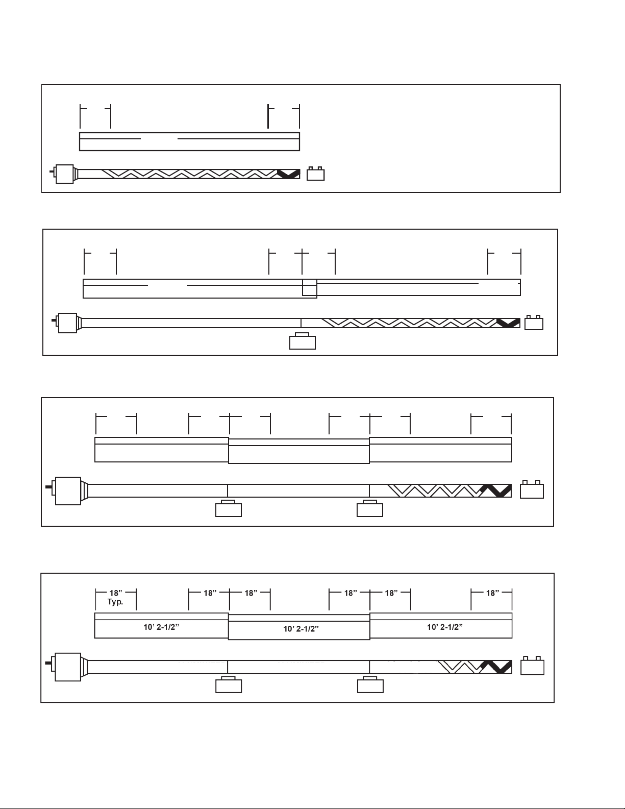
8
Enerco | Calefactor Heatstar ERXL Serie Tubor Instrucciones de uso y manual del usuario
HANGER HANGER
18” 18”
10’ 2-1/2”
ALUMINIZED
AL
UMINIZED
FIGURE 2B: MR. Heater Model 60,000 & 80,000 BTU, Assembly Overview
Intercambiador de 20' de largo. El largo total del calefactor es 21' - 4". 4 puntos de suspensión como se indica.
FIGURA 2A: MR. Heater Model 40,000 BTUIntercambiador de 10' de largo. El largo total del calefactor es 11' -
4". 2 puntos de suspensión como se indica.
HANGER HANGER HANGER HANGER
18” 18” 18” 18”
10’ 2-1/2”
10’ 2-1/2”
ALUMINIZED
2-1/2” OVERLAY TYP
(1) Turbulator Sections
ALUMINIZED
FIGURE 2D: MR. Heater Model 100,000 BTU Assembly Overview
3Intercambiador de 30' de largo. El largo total del calefactor es 31' - 4". 6 puntos de suspensión como se indica.
FIGURE 2C: MR. Heater Model 80,000 BTU,
Intercambiador de 30' de largo. El largo total del calefactor es 31' - 4". 6 puntos de suspensión como se indica.
18” 18” 18” 18” 18” 18”
10’ 2-1/2”
10’ 2-1/2”
10’ 2-1/2”
(1) Turbulator Sections
HANGER HANGER HANGER
Typ.
HANGER
ALUMINIZED ALUMINIZED
9' Long Turbulator Section
10' Long Turbulator Section
5' Long Turbulator Section
10' Long Turbulator Section
GANCHO GANCHO
GANCHO
GANCHO
GANCHO GANCHO
GANCHO GANCHO GANCHO GANCHO
GANCHO GANCHO GANCHO GANCHO
ALUMINIZADO
ALUMINIZADO
ALUMINIZADO ALUMINIZADO
ALUMINIZADO ALUMINIZADO
(1) SECCIÓN DE GENERADOR DE TURBULENCIA (10')
(1) SECCIÓN DE GENERADOR DE TURBULENCIA (9')
(1) SECCIÓN DE GENERADOR DE TURBULENCIA (10')
(1) SECCIÓN DE GENERADOR DE TURBULENCIA (5')

9
Instrucciones de uso y manual del usuarioEnerco | Calefactor Heatstar ERXL Serie Tubor
FIGURA 2E: MR. Heater Model 100,000 & 125,000 BTU
Intercambiador de 40' de largo. El largo total del calefactor es 41' - 4". 8 puntos de suspensión como se indica.
FIGURA 2F: MR. Heater Model 125,000 , 150,000, 175,000 BTU
Intercambiador de 50' de largo. El largo total del calefactor es 51' - 4". 10 puntos de suspensión como se indica.
FIGURE 2G: MR. Heater Model 150,000 & 175,000 BTU
Intercambiador de 60' de largo. El largo total del calefactor es 61' - 4". 12 puntos de suspensión como se indica.
10’ 2-1/2” 10’ 2-1/2”
10’ 2-1/2”
10’ 2-1/2”
10’ 2-1/2”
18”
Typ.
ALUMINIZED ALUMINIZED ALUMINIZED ALUMINIZED ALUMINIZED
18” 18” 18” 18” 18” 18” 18” 18” 18”
10’ 2-1/2” 10’ 2-1/2” 10’ 2-1/2”
10’ 2-1/2” 10’ 2-1/2” 10’ 2-1/2”
18”
Typ.
ALUMINIZED ALUMINIZED ALUMINIZED ALUMINIZED ALUMINIZEDALUMINIZED
18” 18” 18” 18” 18” 18” 18” 18” 18” 18” 18”
ALUMINIZED ALUMINIZED ALUMINIZED ALUMINIZED
18”
Typ.
18”
18”
18”
10’ 2-1/2”
10’ 2-1/2”
10’ 2-1/2”
10’ 2-1/2”
18"
18"
18"
18"
18"
18"
18"
ALUMINIZADO ALUMINIZADO ALUMINIZADO ALUMINIZADO
ALUMINIZADOALUMINIZADOALUMINIZADOALUMINIZADOALUMINIZADO
ALUMINIZADO ALUMINIZADO ALUMINIZADO ALUMINIZADO ALUMINIZADO ALUMINIZADO
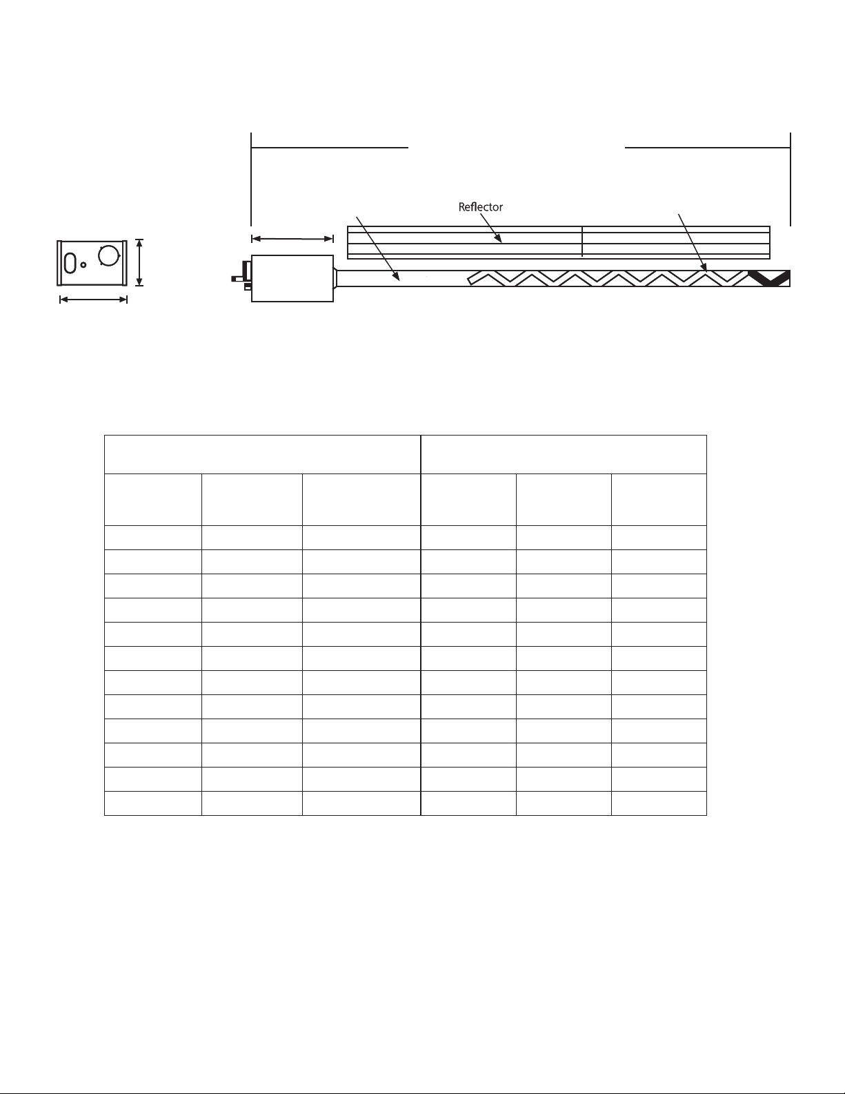
10
Enerco | Calefactor Heatstar ERXL Serie Tubor Instrucciones de uso y manual del usuario
FIGURA 3: Dimensiones y alturas sugeridas de montaje para el MR. Heater
(someModels)
Turbulator
HeatExchanger
Tubing
(someModels)
Turbulator
HeatExchanger
Tubing
MinimumTotalLength(seechartbelow)
Vista lateral del
quemador
Capacidades del quemador y longitudes del
intercambiador de calor: (GN y PL)
Alturas de montaje sugeridas
Capacidad
(BTU/h)
Baja-Alta
Largo del
intercambiador
de calor
Generador de
turbulencia
Largo total
mínimo
Espacio
mínimo
sugerido
Altura típica
de montaje
40,000 10ft. 9ft.
10'-4' 8'-10' 10’-14'
60,000 20ft. 10ft.
21'-4' 10’-12’ 10’-14’
80,000 20ft. 10ft.
21'-4' 12’-15’ 12’-15’
80,000 30ft. 10ft.
31'-4' 12’-15’ 12’-15’
100,000 30ft. 5ft.
31'-4' 12’-15’ 12’-15’
100,000 40ft. Ninguno
41'-4' 15’-18’ 12"-15'
125,000 40ft. Ninguno
41'-4' 15’-20’ 14’-19'
125,000 50ft. Ninguno
51'-4' 15’-18’ 14’-19'
150,000 50ft. Ninguno
51'-4' 20’-23’ 15’-25'
150,000 60ft. Ninguno
61'-4' 20’-25’ 15’-25'
175,000 50ft. Ninguno
51'-4' 20’-23’ 15’-25'
175,000 60ft. Ninguno
61'-4' 20’-25’ 15’-25'
Vista posterior del
quemador
9.25"(23.49cm)
9.25"(23.49cm)
17.75"(45.08)
Tubería del intercambiador de calor
Generador de turbulencia
(SI ES NECESARIO)
Largo total mínimo
(ver el cuadro de abajo)

11
Instrucciones de uso y manual del usuarioEnerco | Calefactor Heatstar ERXL Serie Tubor
U-TubeFittingDimensions 180°U-Tube
18" (45cm)
10"
(25cm)
(10cm)
(43cm)
9"
(22cm)
Radius
Acoples: Latuberíaylosacoplesseconectanmediante
acoplesenvolventesqueseenganchanconuna
trabacónico,ajustadaagolpes.Losextremos
deiniciodelmiembrodeacopleytrabaestán
identificadosmedianteorificiosde1/4"quese
juntanalcomenzaraarmarlo.Verifiquequelos
extremosdeltuboesténalineadosyquetoquen
losretenesqueestándentrodelacople.Hayque
martillarlabarradeslizadorahastaqueelacople
quedebienajustadoalrededordelostubos.El
ajustarlodemasiadocausaráunadistorsiónen
elacopleoenelbordedeldeslizador,locual
disminuirálacapacidaddesujecióndelmismo.
(VerFigura4)
MECANISMO DE ACOPLE
Acople (sin encastre) - 14612
Encastre para el acople - 14616
Orientcouplingsothat
theimpactblockisabove
tubecenterline.
ACOPLEDETUBERÍA
ENCASTREPARAELACOPLE
FIGURA 4:
FIGURA 5: instalación de codo y acople
Paquetedecodo: Elpaquetedecodo(parte#F106415)incluye:
(1)codo,(1)acople.
Instaleelcododentrodelasecuenciadeltuboradiante
cuandolosplanosindiquenunacurvade90°
Dimensionesdelacoplamientodecodo Codode90°
ElpaquetedetuboenU(parte#F106414)incluye:
(1)tuboU,(1)acople.
InstaleelcododetuboenUdentrodela
secuenciadeltuboradiantecuandolosplanos
indiquenunacurvade180°.
(38.73 CM)
(15.24 CM)
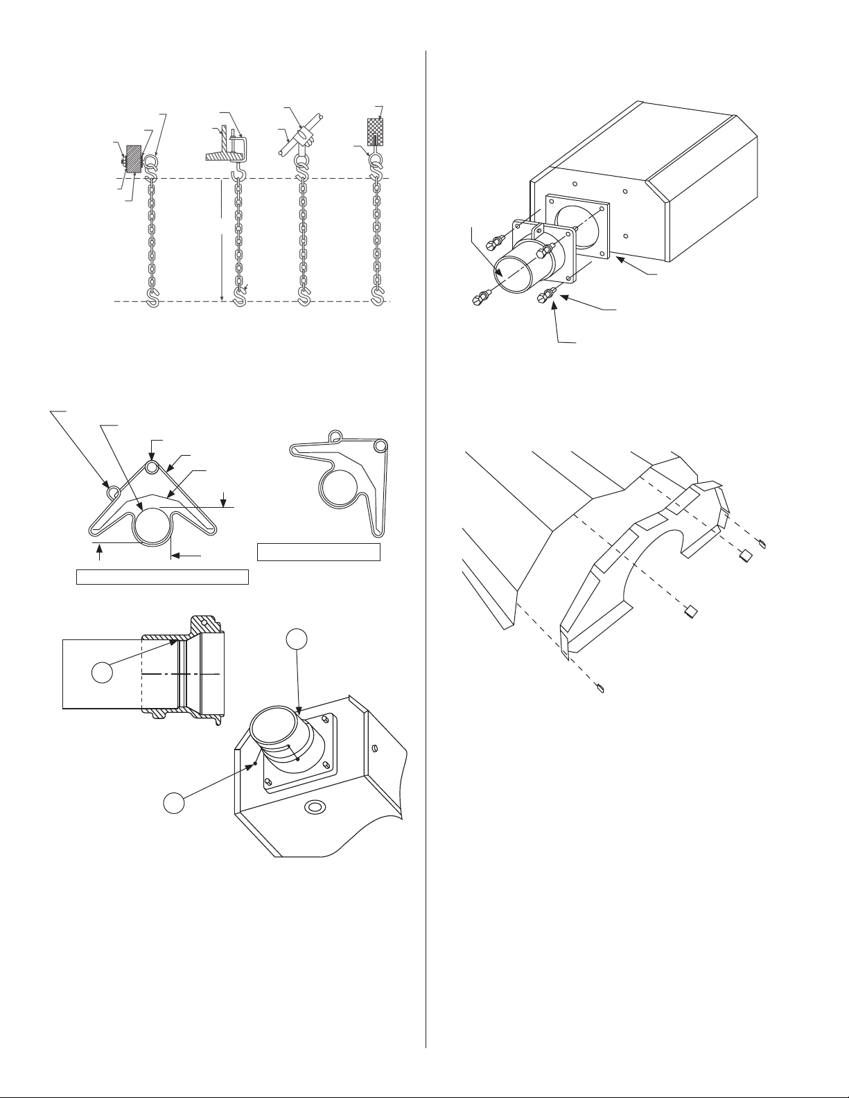
12
Enerco | Calefactor Heatstar ERXL Serie Tubor Instrucciones de uso y manual del usuario
Juegodecadena-Parte#17370
Unjuegodecadenasoportaunaseccióndetuberíade10'yuna
seccióndereflectorde10'.
FIGURA 7A: Gancho para colgar tubos y reflectores
FIGURA 7B: Detalle de la brida de montaje/tubo
1)Inserteeltubo06413dentrodelapiezadefundición
hastaelpunto(A).
2)Ajustelostornillosdeinstalaciónmarcados(B)hastaque
quedebiensujetado.
3)Cuandolos(3)tornillosdeinstalaciónesténajustados,
gírelos1/4devueltaadicionalparaasegurareltuboen
ellugar.
FIGURA 8: Detalle de la caja del quemador/tubo de
transición
FIGURA 6: Detalles de suspensión típica
Tuercade
fijación
Arandela
Vigade
madera
Arandela
Tornillocongancho
min.3/8"(10mm)
Viga I
Gancho
paraviga
Comosea
necesario
Gancho “S”
Ganchopara
vigueta
Cercha
Viga de
concreto
Anclaje
Bridademontaje
Tornillo
Parte#98012
Arandeladeretención
Parte#98527
Junta
Parte#12397
Caja del quemador
(ventanadeobservación
delallamaapuntando
haciaabajo)
posiciÓn De reflector HoriZontal (estÁnDar)
anillo De MontaJe en ÁnGUlo
tubo radiante
anillo de montaJe horizontal
gancho
reflector
parte superior
costado
posiciÓn De reflector a 45°
(opcional)
parte inferior
A
B
FIGURA 9: Tapa del extremo del reflector
Listadepartes
100419Tapadelextremodelreflector(1)
209369Ganchoaresorte(4)
Juegodebrida#06428XL
Eljuegoincluye:Brida,tornillos(4),arandelasderetención(4),junta(1)
B

13
Instrucciones de uso y manual del usuarioEnerco | Calefactor Heatstar ERXL Serie Tubor
SECCIÓN 4
Especificaciones de ingeniería
Eldiseñodelsistemacompletodecalefaccióndebeestarcertificado
porCSAbajolaúltimaversióndeANSIZ83.20andCSA2.34.
A. Quemador y controles del quemador
1.Losquemadoresdebensercapacesdeencenderconunadelas
opcionesdecombustibleespecificadasenlosdocumentosde
compra:GasnaturaloPL.
2.Losquemadoresdebensuministrarseparatrabajaracualquiera
delosnivelesdeentradaespecificados.
40,000BTU/Hr. 125125,000BTU/Hr.
60,000BTU/Hr. 150150,000BTU/Hr.
80,000BTU/Hr. . 100,000BTU/Hr.
175,000BTU/Hr.
3.Quemadordeberáestarequipadoconunsistemadesentido
directodecarburodesiliciosuperficiecalientedecontrolde
encendidocon100%dedispositivodeencendidodecierre.Po-
tenciasuministradaacadacalentadordebeserde120V,60Hz,
monofásica.Quemadoresseránclasificadospara1.0amperios
(pista)y5,0Amp(inicio).
4.Quemadorestaráequipadoconproteccióntérmicadelmotor
sobrecarga,rotordeaireequilibrada,presostatodeseguridadde
comprobacióndeairedecombustión,ylaventanadevisual-
izaciónparalaobservacióndelallama.
5.Cuandoseespecifica,enambientescontaminados,elquemador
serácapazdesuministraraireexteriorparacadaquemadorpara
elapoyodelacombustión.
6.Todoslosquemadoresdeberánserpre-cableadoconuncablede
conexiónatierrayunenchufe.
7.Aeleccióndelcliente,losquemadoressepuedencontrolar,ya
seaconuntermostatodetensióndelíneaopcionaloportermo-
statosdebajovoltajeopcionalconunrelédetransformadorde
bajatensiónadecuada.
8.Elsuministrodegasalosquemadoresseajustaráalosiguiente:
2.1"TamañodelconectordegasNPT
NaturalGas: 4.6”W.C.MIN,7.0”W.C.MAX
LPGas: 11”W.C.MIN,14.0:W.C.MAX
B. Intercambiador de calor
1.Latuberíaradiantedebeserdeaceroaluminizadocon
undiámetrode4",enseccionesde10'delargo.Las
seccionesdebenunirseconacoplesenvolventesdeacero
inoxidable.
2.Elreflectordebeserdealuminioydebeestardiseñado
paradirigirtodoelcalorradiantehaciaabajodelalínea
centralhorizontaldeltuboradiante.
3.Loscalefactoresdebenventearsedeacuerdoconlasreco-
mendacionesdelfabricante.
Presión en la ENTRADA de gas:
Natural Gas: 3.5” W.C.
LP Gas: 10.5” W.C.
ConectordegasNPTde1/2”
Gas INLET pressure:
Natural Gas: 4.6” W.C. Min
11.0” W.C. Max
LP Gas: 11.0” W.C. Min
14.0” W.C. Max
ConectordegasNPTde1/2”
Alimentación:(Todoslosmodelos)
120V-60Hz
1.0AMP(Run)5.0AMP(Start)
Dimensiones:
Tamaño de conexión de combustible………4”
Tamaño de conexión de aire exterior………4”
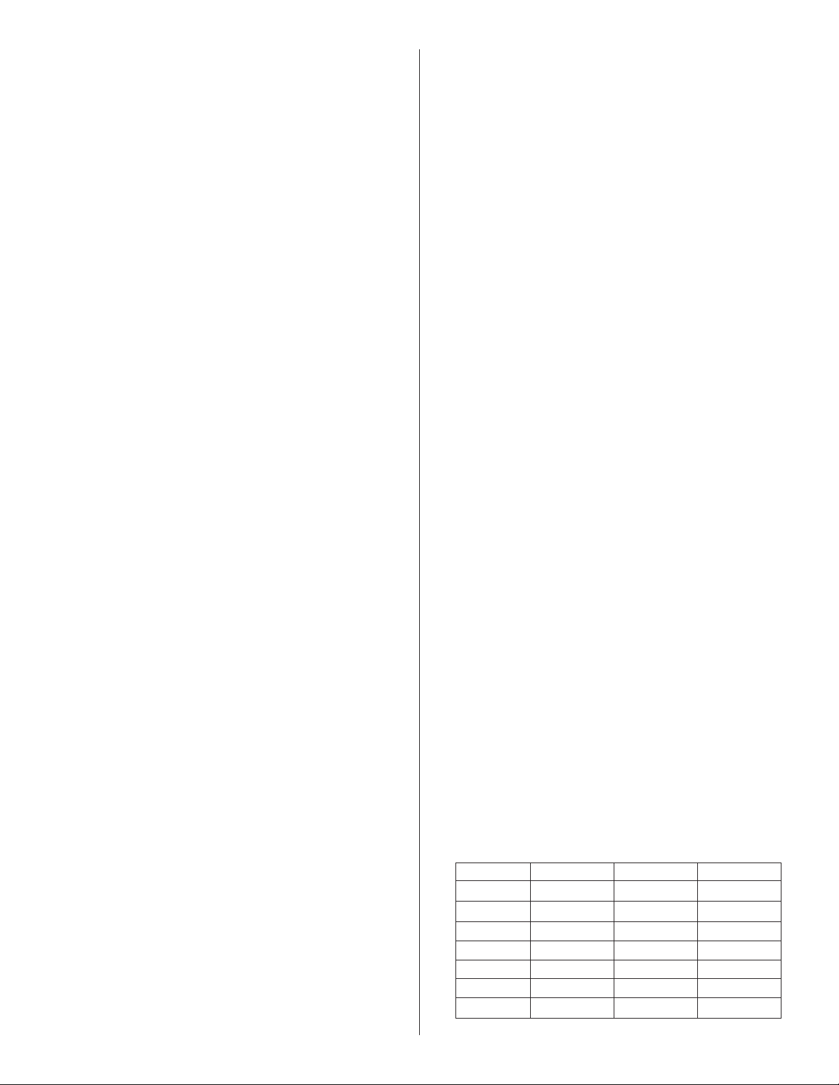
14
Enerco | Calefactor Heatstar ERXL Serie Tubor Instrucciones de uso y manual del usuario
VENTEO COMÚN - (2) Calefactores (horizontal y vertical)
Modelo# H=6ft. H=8ft. H=15ft.
40,000BTU
D=7" D=6" D=6"
60,000BTU
D=7" D=6" D=6"
80,000BTU
D=8" D=7" D=6"
100,000BTU
D=8" D=8" D=7"
125,000BTU
D=10" D=10" D=8"
150,00BTU
D=10" D=10" D=8"
175,000BTU
D=10" D=10" D=8"
SECCIÓN 5
Venteo / conductos
Requisitos generales
Estecalefactordebeventearsedeacuerdoconlasespecifica-
cionesincluidasenestemanualyconlassiguientesnormasna-
cionalesycontodaslasnormasestatales,provincialesolocales
quecorrespondan:
•ConsulteelCódigonacionaldelgascombustibleNFPA54/
ANSIZ223.1-últimaversión.
•CANADÁ:ConsulteelCódigodeinstalacióndegasnaturaly
propano,CSAB149.1-últimaversión.
Sepuedeventearelcalefactoralexteriordeformaverticalu
horizontal.
Elsuministroopcionaldeaireexteriorsepuededirigirhaciael
calefactordeformaverticaluhorizontal.
Asegúresedequeelmétodoseleccionadoparaventearel
calefactorcumplacontodaslasnormasnecesariasparacada
ubicaciónenparticular.Serecomiendautilizarunatuberíade
venteodeparedsimple(calibre26).Serecomiendaunasección
detuberíadeventeoconpareddoblealpasaratravésdel
techoodelapared.
Elextremodeescapedelcalefactoraceptaráuntubodeventeode
4'(10cm)usandoeladaptadordeventeo.Instaleeladaptadorde
venteoconlacosturahaciaarriba,fijetodaslasunionesdelventeo
con3tornillosparametal#8x3/8"comomínimoyselletodaslas
unionesconunselladordesiliconaparaaltatemperatura.
Silacondensaciónenelconductorepresentaunproblema,
deberíaacortarsesulongitudoaislarlo.
Eltubodeventeodebetenerunapendientehaciaabajo(al
alejarsedelquemador)de1/4"(0.6cm)porcada10'(3m).
LONGITUDESDELVENTEO
•Ellargototalmáximopermitidodelventeoesdetreinta(30')pies.
•ELconductodesuministrodeaireexteriorpuedetenerhasta
unmáximodetreinta(30')pies.
•Ellargototalmáximodelventeomáselconductode
suministrodeaireexteriornodebeexcederloscincuenta
(50')pies.
NOTA:
Sepermiteunmáximodedos(2)codosporcombinaciónde
venteoysuministrodeaireexterior.Substraiga5'dellargo
máximopermitidoporcadacodoadicionalsiseutilizan3omás
codos.
Instaleuntuborectode18"(30cm)comomínimoparaantes
decadaTocodoenlaentradadeaireexterioroelventeo.
Arreglos alternativos/Equipo opcional para ventear
instalaciones sin venteo
a)Hayquesuministrarsuficienteventilaciónsiguiendolaregla
de4CFMporcada1.000BTU/h.
b)ConsultelasnormasANSIZ223.1-últimaversión,NFPA-54y
lasnormaslocalesporinformaciónadicional.
c)Noserecomiendaelusoairedecombustiónexterioropcional
concalefactoressinventeodebidoalasconsideracionesde
presión.Consultelapágina16
Venteo horizontal
a)Senecesitaunatuberíadecuatro(4")pulgadasdeD.E.Se
recomiendaunlargomáximodetreinta(30')pies.
b)Todaslasunionesdelatuberíadebensellarseconun
productoadecuadocomoGeneralElectricRTV106oPermatex
Form-A-GasketRedHighTemperatureSiliconeAdhesive
Sealant.
c)Noinstaleningúncodooacoplede45°parabajarelventeo
pordebajodelsistemahorizontaldetuberías.
d)Elterminaldeventeodebeinstalarseaunaalturasuficiente
comoparaevitarquesetapeconnieve.
1)Elventeodebesalirdeledificioanomenosdesiete(7')pies
sobreelniveldelsueloalcolocarlojuntoalavíapública.
2)Elventeodebeterminarporlomenosatres(3')piespor
encimadetodaentradadeaireforzadoubicadadentrode
losdiez(10')pies.
3)Elventeodebeterminarporlomenosacuatro(4')piespor
debajo,cuatro(4')piesalcostadoyun(1')pieporencima
decualquierpuerta,ventanaoentradaporgravedadde
cualquieredificio.
4)Elterminaldeventeodebeestarubicadoporlomenosa
doce(12")pulgadasdecualquieraberturaporlaquelos
gasesdeventeopodríanentraraledificio.
5)Elterminaldeventeodebeestarporencimadetoda
cornisadematerialcombustible
Venteo vertical
a)Sepuedeusarunatuberíadecuatro(4")pulgadasdeD.E.y
treinta(30')piesdelargocomomáximocomosemuestra,
conunatapadeventeoaprobada.(VerlosRequisitos
generalesenestapáginaporinformaciónadicional).
b)Puedenecesitarunguardacaboaisladoparapasaratravésde
estructurascombustibles(consultelasnormaslocales).
c)Todaslasunionesdelatuberíadebensellarseconproductos
adecuados(verlasrecomendacionesparaventeohorizontal).
Venteo común
a)Elrecorridohorizontalalventeonuncadebeexcederel
75%delaalturaverticaldelventeo.Consultelasnormas
ANSIZ223.1-últimaversión,NFPA-54porlostamañose
instalacionesadecuadasdeventeo.
b)Eláreaabiertadeventilaciónencomúndebeserigualala
sumadeláreaabiertadelosventeosindividualesconectadosa
lamisma.(Verelcuadrodeabajoylosdiagramas-página14).
c)Useventeosdepareddoblecuandoseanecesario(consulte
lasnormas).
d)Todaslasunionesdebensellarseconunproductoadecuado.
e)Lasconexionesaunatuberíaencomúndebenubicarsede
talformaqueevitelaoposicióndirectadecorrientesdegases
decombustión.

15
Instrucciones de uso y manual del usuarioEnerco | Calefactor Heatstar ERXL Serie Tubor
FIGURA 12: Ventilación común de techo
HORIZONTAL COMMON VENTING
SIDE VIEW
TOP VIEW
Type "B" Vent required outdoors.
Vent Adapter Stk. #19021
At least 1/4" per foot rise or pitch
must be maintained on horizontal
runs from heater to vent.
Roof
Secure all joints with 3 (minimum) #8 x 3/8"
sheet metal screws and seal all joints.
H
Approved Vent Cap
Type "B" Vent required outdoors.
Vent Adapter Stk. #19021
Outside Wall
H
Vent Cap
Flashing
Wall Thimble
(If Applicable)
Burner Box
Burner Box
Burner Box
Burner Box
Burner Box
Burner Box
D
Burner Box Burner Box
D
4” Aluminized steel Heat Exchange Tube
4” Aluminized steel Heat Exchange Tube
Type"B"Ventrequiredoutdoors.
VentAdapterStk.#19021
OutsideWall
Securealljointswith3(minimum)#8x3/8"
sheetmetalscrewsandsealalljoints.
H
VentCap
WallThimble
(IfApplicable)
BurnerBox
BurnerBox
D
D
VENTILACIÓN COMÚN HORIZONTAL
VENTILACIÓN COMÚN VERTICAL
VISTALATERAL
Adaptadordeventeo
Part#19021
Cajadelquemador
Tapaaprobadadeventeo
Láminaprotectora
Venteotipo"B"necesarioalexterior.
Techo
Aseguretodaslasunionescon3tornillosparametal
#8x3/8"comomínimoyselletodaslasuniones.
Cajadelquemador
Guardacabodepared
(siesnecesario)
Tapadeventeo
Paredexterior
Venteotipo"B"necesarioalexterior.
Aseguretodaslasunionescon3tornillosparametal#8
x3/8"comomínimoyselletodaslasuniones.
Cajadelquemador
AdaptadordeventeoParte#19021
Cajadelquemador
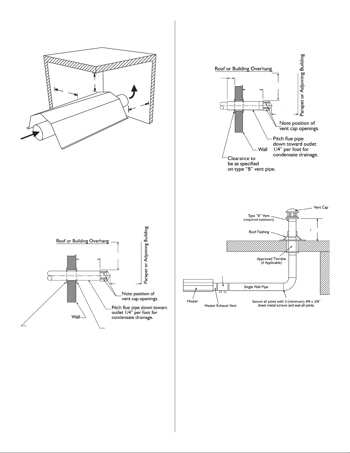
16
Enerco | Calefactor Heatstar ERXL Serie Tubor Instrucciones de uso y manual del usuario
FIGURE 10: Unvented Operation
36”
36”
A
1. Hayquesuministrarunaventilaciónde4CFMporcada1.000
BTU/heninstalacionesdecalefactorsinventeo.
2. ParaladimensiónA"sinventeo"consulte:Figura1-Distancias
mínimasamaterialescombustibles.
FIGURA 10A: Pared simple
Venteodeparedsimple
Terminacióndeextremoparaparedsimple
FIGURA 10b: Pared doble
Venteodepareddoble
Terminacióndeextremoparapareddoble
FIGURA 11: Venteo vertical
18"(45cm)
18" (45cm) Min. 3'-0" (91cm) Min.
8"(20cm) to 10"(25cm) Max.
6' (182cm) Min.
18" (45cm) Min. 3'-0" (91cm) Min.
6' (182cm) Min.
2"(5cm) Clearance thimble
2"(5cm) Clearance thimble
required when u pipe
extends through
combustible materials
(91cm)
(91cm)
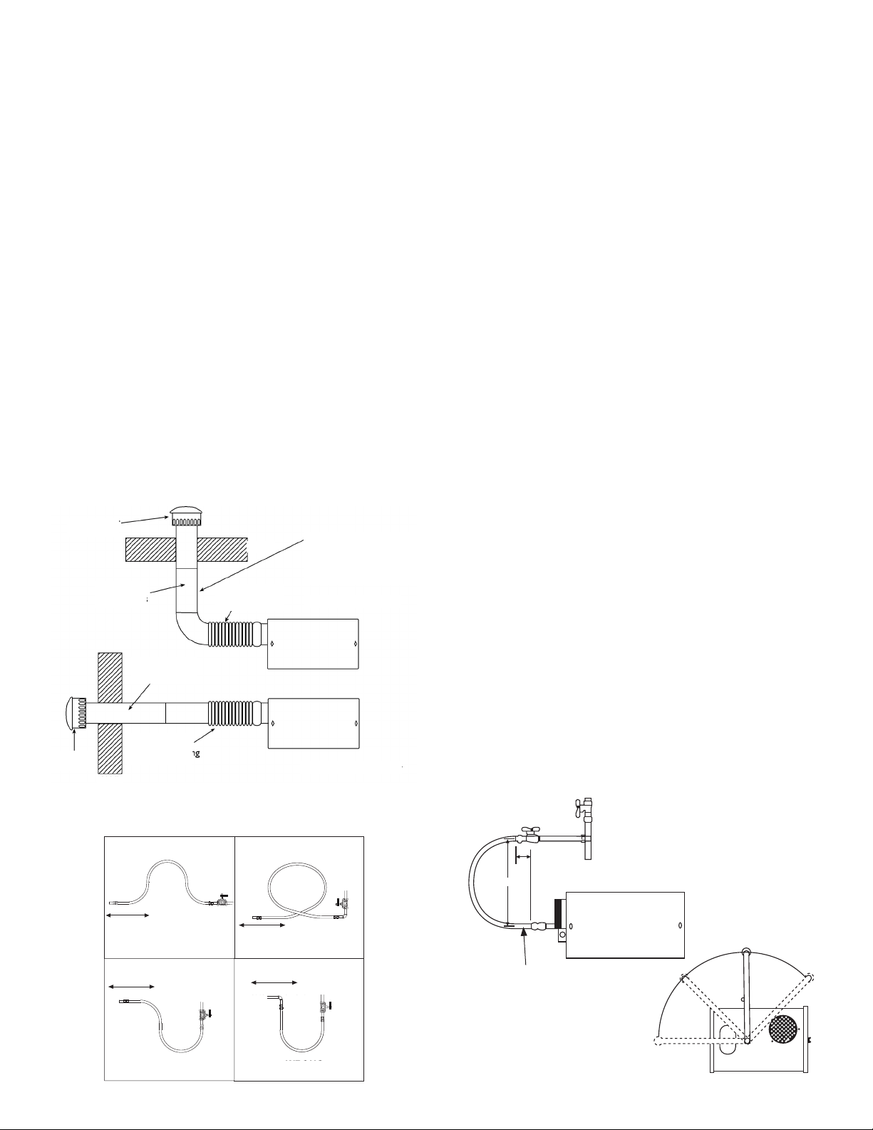
17
Instrucciones de uso y manual del usuarioEnerco | Calefactor Heatstar ERXL Serie Tubor
Suministro de aire exterior para combustión
ElcalefactorMR.Heaterestáaprobadoparainstalarloconun
sistemadesuministrodeaireexterior.Algunoscompuestos
comoloshidrocarburoshalogenadosyotrosquímicoscorrosivos
delairepuedeningresaralequipoycausarlacorrosión
prematuradealgunosdeloscomponentesdelcalefactor.Hay
queevitarelusodedichoscompuestosquímicoscercadel
lugar.
IMPORTANTE: Si el edificio tiene una presión levemente
negativa o existen contaminantes en el aire, le
recomendamos seriamente instalar un suministro de aire
exterior de combustión para los calefactores.
Puedecolocarunatuberíadeparedsimpledecuatro(4")
pulgadasdeD.E.paraelsuministrodeaireexterior.Elconducto
puedetenerhasta(30')piesdelargocomomáximoodos
(2')piescomomínimoconnomásdedos(2)codos.(Verlos
Requisitosgeneralesenlapágina15porinformaciónadicional).
Elconductodeaireexteriorpuedenecesitaraislaciónpara
evitarlacondensaciónenlasuperficieexterior.Elterminal
deaireexteriordebeestarfirmementeaseguradoalapared
exteriorhaciendocuatro(4)orificiosde1/4"dediámetroenla
bridaexterior.Sepuedenusartornillosopernosparamaderay
mangasdeexpansiónparasujetarelterminal.
SepuedeusartuberíadePVC,una"mangueraseca"o
equivalenteenlugardelatuberíaestándardeventeo.
FIGURA 13: Conducto de suministro de aire exterior no
presurizado
SECCIÓN 6
Tubería de gas
LealasadvertenciasquecorrespondanenlaSección1antesde
comenzarconlainstalacióndelatuberíadegas.Unainstalación
inadecuadapuedecausardañosmateriales,lesionesgravesola
muerte.
Elmedidorylatuberíadebenserlosuficientementegrandescomo
paramanejartodoslosquemadoresqueseesténinstalandomás
cualquierotracargaconectada.Lalíneadegasquealimentaal
sistemadebeserlosuficientementegrandecomoparasuministrarel
gasnecesarioconunacaídadepresiónmáximade1/2"decolumna
deagua.Cuandonoseincluyelatuberíadegaseneldiagrama
dedistribución,elproveedorlocaldegasnormalmenteayudaráa
planificarla.
Hayquecolocarunaderivaciónde1/2"enlaubicacióndecada
quemador,orientadacomosemuestraenlaFigura14.Paraprobarla
presióndelsistema,enchufeunaderivaciónNPTde1/8"enlalínea
degasenlaconexióndelquemadorqueestémáslejosdelaentrada
desuministro.Antesdeconectarlosquemadoresalsistemade
suministro,verifiquequesehayancompletadotodaslaspruebasde
altapresióndelatuberíadegas.Norealicelapruebadealtapresión
delatuberíadegasconlosquemadoresconectados.
Sigaestasinstruccionesparaasegurarunainstalaciónprofesionaldel
suministrodegas:
•Sostengatodalatuberíadegasconmaterialesadecuadospara
colgartuberías.
•Usetuberíadehierroforjadooaceroforjadoyacoplesde
hierromaleable.Todoslosacoplesdebensernuevosynotener
defectos.Escariarcuidadosamentelosextremosdeloscañosy
tuberíaspararemoverobstruccionesyrebabas.
•UsecompuestoresistentealgasPLentodaslasroscasdelos
caños.
•Verifiquequeningunodelosextremosdeloscañosytuberías
tengafugasantesdeponerenmarchaelequipodecalefacción.
Useunasolucióndeaguayjabónparaverificarquenoexistan
fugasdegas:NUNCA USE UNA LLAMA.
Instaleelconectorflexibleparagascomosemuestra.Elconector
flexibleparagaspermitelaexpansióndelsistemadecalefaccióny
facilitalainstalaciónyreparacióndelquemador.
FIGURA 14: Conexión de línea de gas con conector de acero
flexible para gas
Lallavedepasodebequedarparalela
alaentradadegasdelquemador.El
desplazamientode2"indicadoesparala
condicióndefrío.Estedesplazamiento
sepuedereduciralencenderelsistema.
Llavedepaso
12 "
2"
Conectorflexibledeaceroinoxidableparagasde1/2"
Parte#16401
90°
45°
0°
45°
Heater Movement
Heater Movement
Heater Movement
Heater Movement
FIGURA 14A: Conexión incorrecta de línea de gas con
conector de acero flexible para gas
3" (10 cm)
Sellar todas las
juntas
Terminación de
aire exterior
Caño exible
De 6" (15 cm) a 12"
(30 cm) de largo
Caño exible
De 6" (15 cm) a 12"
(30 cm) de largo
Terminación
de aire exterior
NOTA:
Las tuberías necesitan soporte
adicional. El caño exible no
puede soportar el tubo vertical y
la terminación de aire exterior
Aire exterior vertical
Aire exterior horizontal
Pared
Techo
3" (10 cm)
Sellar todas las
juntas
INCORRECTO
INCORRECTO
INCORRECTO INCORRECTO
Movimientodelcalefactor
Movimientodelcalefactor
Movimientodelcalefactor
Movimientodelcalefactor
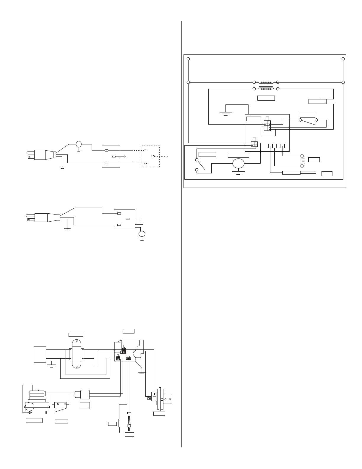
18
Enerco | Calefactor Heatstar ERXL Serie Tubor Instrucciones de uso y manual del usuario
SECTION 6
CABLEADO
Calentadoressonnormalmentecontroladosportermostatos.
TermostatostensiónLineseconectandirectamente(verFigura15),
termostatos24Vseconectandirectamenteatravésdelosterminales
delacajadelquemador(verFigura16).Loscalentadoresdeben
estarconectadosatierradeconformidadconelCódigoEléctrico
NacionalANSI/NFPA-70oactualCódigoEléctricoCanadiense,CSA
C22.1.Calentadorestambiénpuedencontrolarseconuninterruptor
devoltajedelíneamanualointerruptordetiempoenlugardel
termostato.
FIGURA 15: Voltaje de línea termostato Cableado
T
H
N
120v – 60 Hz
White
White
Green
Green
Supply Circuit
120v – 60 Hz
Supply Circuit
Burners
(Maximum – 2 per Thermostat)
Burners
(Maximum – 1 per Thermostat)
Black
Black
H
N
T
T
H
N
120v – 60 Hz
White
White
Green
Green
Supply Circuit
120v – 60 Hz
Supply Circuit
Burners
(Maximum – 2 per Thermostat)
Burners
(Maximum – 1 per Thermostat)
Black
Black
H
N
T
FIGURE 18: MR. Heater Burner Internal Wiring Ladder Diagram
FIGURA 17: MR. Heater Quemador Cableado
•Sialgunodeloscablesoriginalestalcomosesuministra
conelaparatodebeserreemplazado,debeser
reemplazarconmaterialdecableadoquetieneungrado
delatemperaturadealmenos105°Cy600voltios.
•Cadaquemadortienequeestarconectadaatierrade
acuerdoconlaNationalElectricCodeANSI/NFPA-70
orcurrentCanadianElectricalCode,CSAC22.1.
VAC
120
120V
24V
Black
Black
Purple
Yellow
Yellow
Black
Black
Black
Green
Green
Orange
Transformer
White
White
White
THERMOSTAT
White
Blue
Gas Valve
Air Switch
Ignitor
Sensor
Motor / Blower
Door Switch
Terminal
Bushing
120V
L2
(NEUTRAL)
White
White
White
White
White
White
Gray
Orange
Transfomer
Thermostat
Air Switch
Gas Valve
Door Switch
Motor / Blower
Ignitor
Sensor
Blue
Yellow
Yellow
Purple
Black
Black
Black
Black
L2 (HOT)
24V
FIGURA16: Baja Tensión termostato Cableado

19
Instrucciones de uso y manual del usuarioEnerco | Calefactor Heatstar ERXL Serie Tubor
5. Reviseelinteriordeltubodetiroconunalinterna.Siel
carbonoolaescalaestánpresentes,rasparlosdepósitoscon
uncepillodealambreovarillaoplacametálicaunidaaun
postedemadera.
6. Compruebequelaventanadeobservaciónquemadorestá
limpiaylibredegrietasoagujeros.Limpieoreemplace
segúnseanecesario.
7. 7.Compruebeelconductodehumosdehollínosuciedad.
Despuésdelalimpiezasiesnecesario,vuelvaacolocarel
tubodeescapedelcalentador.
8. 8.superficiesexterioresdelcalentadorpuedenlimpiarsecon
unpañohúmedo.
9. 9.Unaagenciadeserviciocualificadodebesercontactado
porelservicioquenoseaelmantenimientoderutina.
10. 10.Compruebeelterminaldeventilaciónyentradade
airefrescoalverquenohansidobloqueadosdurantela
temporadanosecaliente.Sibienlatuberíaestárestringido,
elinterruptordeairenosecerrará,loqueresultaenuna
situaciónsinsalidadecalor.T
Solución de problemas
PRECAUCIÓN:Antesdeabrirlapuertadel
quemadorEner-RadianteXLparacualquier
tipodeservicio,asegúresedequeel
suministrodegassehaapagadoenel
calentadoryelcableeléctricodelacajadel
quemadorhasidodesconectado.
Motor del ventilado1.¿Eseltermostatopidecalor?Estáahí
No se ejecuta: 115Venelreceptáculodelquemador?
2.Compruebelapuertadelladodelventilador
paraelsello.Reviseelinterruptordela
puerta.Reemplacesiesnecesario/
3.Compruebesopladordeobstrucciones.
Reemplaceventiladorsiesnecesario.
Encendedor
encendedor 1.Compruebesihaydaños.Reemplacesi
No se ilumina: necesario:
2.Comprobarelvoltajeylaresistenciaenel
encendedor.(Elvoltajedebeserde115V.La
resistenciadebeser40-75ohmios.)
3.Compruebesihayobstruccionesala
entradaysalidadeaire.
4.Reviselasconexionesdecablesymangueras
enelinterruptordeaire.Reemplacesies
necesario.
5.Compruebetensionesalprimariodel
transformadorysecundaria.Reemplazar
transformadoromódulosiesnecesario.
Válvula no se
enciende presióndegasaguasabajodelcontroldegas
puedesermedidamedianteelusodeun
manómetroylaconexiónalatomadepresión
enelcontrol/
1.Compruebesielcalentadorválvulamanual
esON.
2.Compruebesiperilladelaválvulamanual
decontroldegascalentadorenON.
3.presióndelgasdealimentaciónsepuede
comprobaren1/8"presiónNPTgolpecitos
SECTION 8
Operation & Maintenance
Sequence of Operation
1. Gireeltermostato.Cuandoeltermostatorequierecalor,el
motordelventiladorseenergizará.
2. CuandoelmotorseacercaRPMdefuncionamientonominal,
elinterruptordeflujodeairesecierrayactivaelmódulode
encendido.
3. Elmódulodeencendidoyluegoactivaelencendedorde
superficiecalienteduranteunperíododecalentamiento
temporizado(aproximadamente45a60segundos.)
4. Despuésdequeelperíododecalentamiento,seenergizala
válvuladegas.
5. Durantelaúltimapartedelasecuencia,elencendedorse
desactivayseconvierteenunavarilladellamadetección.
6. Sisedetectaunallama,laválvuladegaspermaneceabierta.
Cuandolademandadecalorsecumple,yelmecanismode
controldelsistemade-energizaelsuministrodetensióndela
líneadelquemador,lasválvulasdegasestánapagados.
7. Sinosedetectalallamaenunmódulodeunsolointento,la
válvuladegassecierra,yelmódulosebloqueahastaquese
restablece.Restablecerselogramediantelaeliminaciónde
alimentacióndelmódulodeporlomenoscinco(5)segundos
(serequiereciclodeltermostato.)
8. Sinosedetectalallamaenunmódulodetresensayos,la
válvuladegassecierraycomienzaunperiododepurga.
Despuésdelapurga,elmóduloactúaparaaccionar
eldispositivodeigniciónparaunsegundoperíodode
calentamiento,yunsegundojuicioparaelperíodode
encendido.Sitodavíanosehaestablecidolallama,comienza
unatercerayúltimapurga,calentamiento,yelciclode
ensayo.Despuésdetresintentos,elmódulosebloquea
hastaqueserestablezca.Restablecerselogramediantela
eliminacióndealimentacióndelmódulodeporlomenos
cinco(5)segundos(serequiereciclodeltermostato.)
9. Enunmódulodetresjuicio,siseestableceyseperdióen
elprimerosegundoensayodellama,laválvuladegasse
apaga,unapurga,calentamiento,ypruebadeencendido
seproduciráenunmódulodetresensayos,solamente
Sepermitentresensayosparaelencendidoporciclodel
termostato.
Mantenimiento
Paraunmejorrendimiento,lossiguientesprocedimientosde
mantenimientosedebenrealizarantesdecadatemporadade
calefacción:
1. Asegúresedegasysuministrodeenergíaeléctricaal
calentadorestánapagadosantesderealizarcualquierservicio
omantenimiento.
2. Revisarlacondicióndedesplazamientodelventiladory
elmotor.Lasuciedadyelpolvopuedensoplarconaire
comprimidoounaaspiradorasepuedenutilizar.Cuando
seutilizaairecomprimidonoexceda30psiconelfindeno
dañarfrágilesencendedorincandescente.
3. Comprobarelestadodelquemador.Retireconcuidadoel
polvoolosescombrosdelinteriordelacajadelquemadoro
tazaquemador.
4. Inspeccioneelencendedor.Reemplazarencendedorsihay
residuosexcesivosdecarbono,erosión,roturasuotros
defectos.
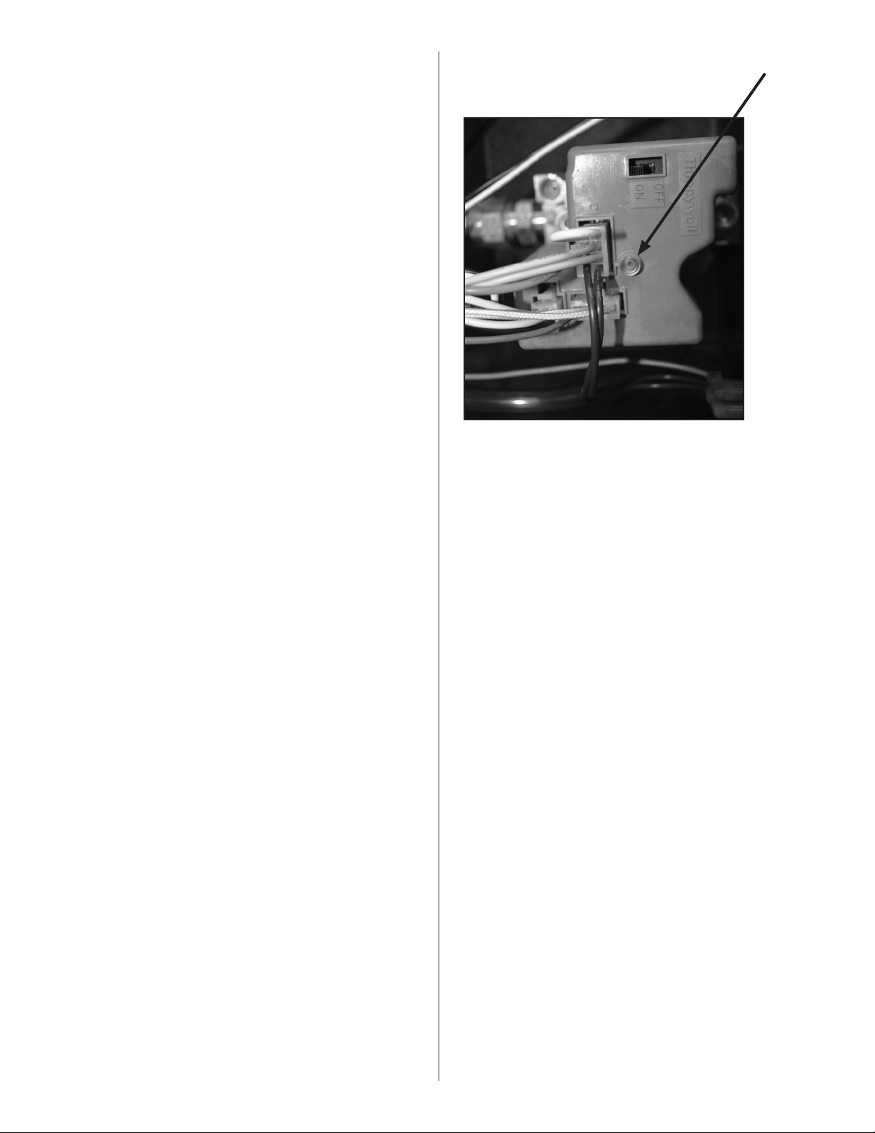
20
Enerco | Calefactor Heatstar ERXL Serie Tubor Instrucciones de uso y manual del usuario
enelcalentadordelaválvulamanual
externa.
4.Compruebesielcontroldegasestá
abriendo:sinpresióndelcolectorindicala
válvulaestácerrada.
Silaválvulaestácerrada,yasealaválvulade
gasoelmódulodeigniciónesdefectuoso.
ADVERTENCIA:Nodesconecteloscables
detierrainsideheater.Donotinterchange
groundedandungroundedleadson
transformerorignitionmodule.
1.Compruebesilaslíneasdegasfueron
adecuadamenteLuz:purgadodeaire.
2.Compruebelapresióndegasdeentraday
salidaduranteelperiododeencendido.
Presióndeentradanaturaldebeser4.6"
Presióndesalidanaturaldebeserde3.5"
PresióndeentradaLPdebeser11.0"
PresióndesalidaLPdebeser10.25"
3.Compruebesielorificioadecuadoylaplaca
deaire.
1.Comprobarlacontinuidaddecableatierra.
ManténgaseLit:cableadointerno
2.Examineelquemadorparacablesinvertidos.
3.Comprobarelaislamientoenelencendedor
conduce.
4.Vuelvaacolocarelmóduloencaso
necesario.Honeywell
Válvula de LED de estado:
ElcalentadordetuboseriesEner-RadianteXLestáequipadacon
unaválvulainteligenteHoneywell.Estaválvulatieneunprograma
dediagnósticointegrado,queayudaráenlasolucióndeproblemas
encasodeunproblemarelacionadoconlaválvula.ElLEDo(Light
EmittingDiode)seencuentraenlapartesuperiordelaválvula
comosemuestraeneldiagramaacontinuación.Lasindicacionesde
estadoLEDseenumeranacontinuaciónparaayudarenlasolución
deproblemas.
OFF INDICADO
Apagado Nohaypoderparaelcontrol
Bright-Dim Funcionamientonormal
Estaindicaciónsemuestracadavezqueseenciendeel
sistema,amenosquehayaocurridoalgúnsuceso
anormal.
2-Flashes Airflowrestosproporcionarinterruptorcerradomás
de30segundosdespuésdelallamadadecalor
comienza(interruptordeaireproporcionandopegado
cerrado.)
3-Flashes Airflowinterruptorproporcionandopermanece
abiertomásde30segundosdespuésdesopladorde
airedecombustiónseactiva-ounsopladornose
energiza.
4-destellosBlancoscablepuenteestásuelto.
5-Flashes Llamaseñaldetectadafueradesecuenciaadecuada.
6-Flashes SistemadeBloqueo.
LED
HoneywellSmartValve
Quemador no se
enciende
Quemador no se
Manténgase Lit:
FIGURA 19
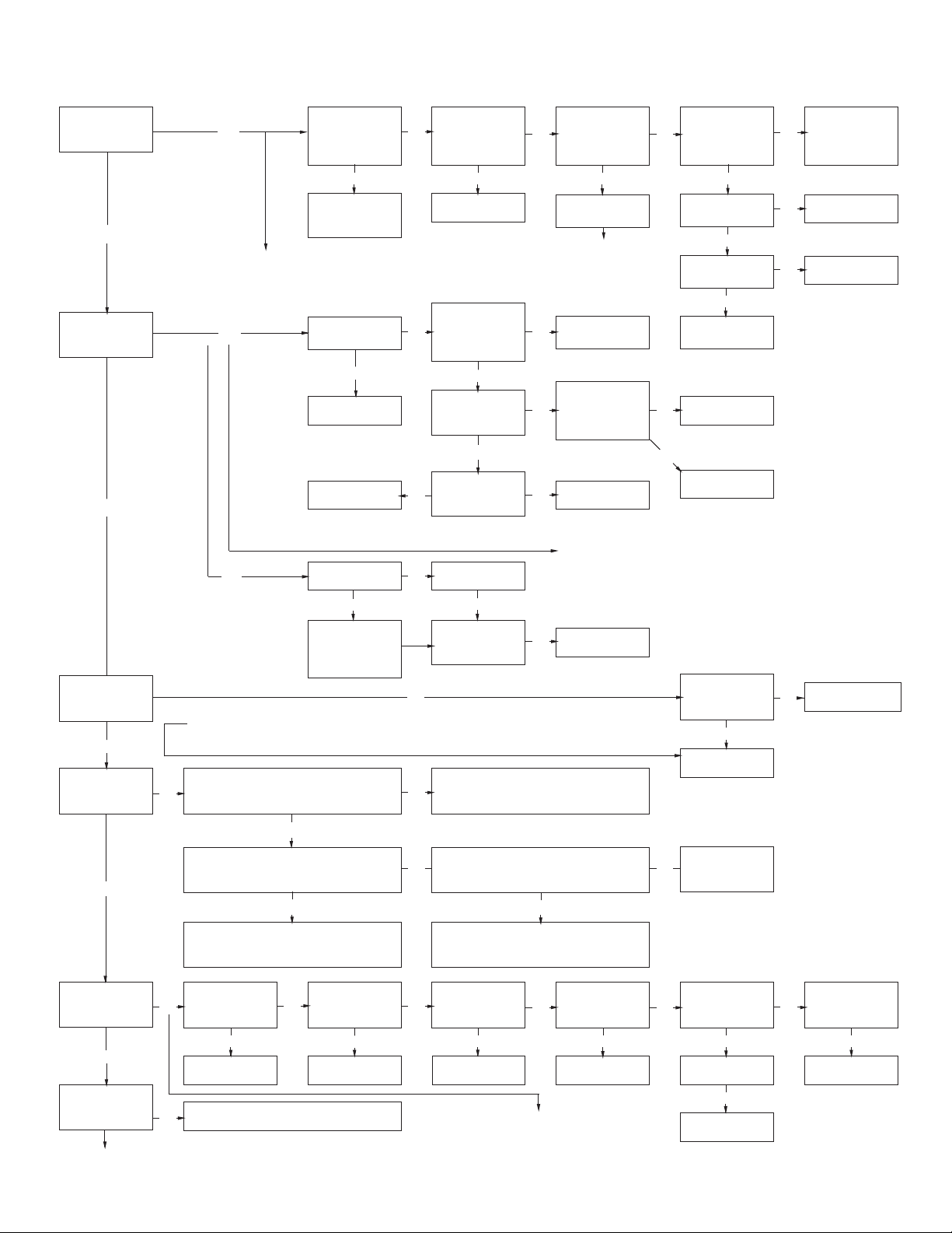
21
Instrucciones de uso y manual del usuarioEnerco | Calefactor Heatstar ERXL Serie Tubor
SECCIÓN 8: Guía de diagnóstico de problemas. Mr. Heater
START
Activareltermostato.
¿Seenciendeel
soplador?
Sí
¿Secalientay
seponerojala
ignición?
Sí
No
Revisareltermostato
yelcableado.¿La
unidadrecibe115vde
alimentación?
No
Buscarelorigendel
problemaeléctrico.
VerelLEDindicadordelcontroldeignición
porindicacióndefalla.Consultarconpruebas
delmódulodeigniciónenlapágina20para
determinarelproblema.
No
¿Estábloqueadala
entradaolasalidade
aire?
Sí
Removerlaobstrucción.
Revisarelcableadoy
lasconexiones.
No
¿Estádañadala
ignición?
No
Verificarelvoltajede
laignición.¿Tiene115
Vduranteelciclode
ignición?
Sí
¿Estácolocadalapuerta
lateraldelsoplador?
No
Reemplazarlapuerta
No
Revisarelcableadoyla
conexióndelamanguera
alinterruptordepresión
deaire.¿Estánbien?
Sí
¿Hay24Venel
secundariodel
transformador?
No
¿Hay115Ven
elprimariodel
transformador?
Reemplazarla
ignición.
Sí
No
¿Laresistenciadela
igniciónesde40-75
ohmios?
Sacarlapuerta.¿El
voltajedelinterruptor
delapuertaes115V?
Yes
No
Revisarelvoltajedel
controldeignición.
Compruebesihayentradadel
transformadorde115VenC3enchufeen
laválvulainteligente.Compruebesihay
salidade115VdeC3.Sinohaytensiónde
salidaestápresentereemplazarlaválvula
inteligente.
Reemplazarelcableado
y/olaconexióndela
manguera.
No
Puentearloscablesdel
interruptordepresión.
¿Seponerojala
ignición?
Sí
Reemplazarel
transformador.
Sí
Revisarlasconexiones
deloscables.
Sí
Presionarelinterruptor.
¿Seenciendeel
soplador?
Sí
Yes
No
Revisarelvoltajedel
motor.¿Es115V?
Sí
¿Estáobstruidoel
soplador?
No
Reemplazarelmotor
delsoplador.
Reemplazarel
interruptordepresión.
Yes
Reemplazarelmódulo
deignición.
No
VerelLEDindicadordelmódulodeignición
porindicacióndefalla.Consultarconpruebas
delcontroldeigniciónenlapágina21para
determinarelproblema.
Revisarelcalcedela
puerta.Siestádañada,
reemplazarlapuerta.
Reemplazarel
interruptor.
No
Removerlaobstrucción
Yes
¿Hacecliclaválvula
despuésdequese
calientalaignición?
Sí
¿Seenciendeel
quemador?
Sí
¿Elquemador
permaneceencendido?
Sí
¿Funcionaelquemador
hastaquenosepida
máscalor?
Sipersisteelproblema,llamaralServicioalclientedeMr.Heater,Inc
TechnicalProductsal1-866-447-2194
No
Elmódulodeigniciónchequeaelestadodeloscontactosdelsensordelsoplador,ydebedetecatrun
cambioenloscontactosporcadaciclodeencendido.Elpuentearelinterruptorfueradelasecuencia
causaráunafallayharáqueelLEDindicadordestelledosveces.
¿Sepurgóelairedelaslíneasdegas?
No
No
Sí
Revisarlapresióndeentradadegas.¿Eslapresión
correcta?Consultelapágina12porlapresióncorrecta.
Sí
Revisarlallavedepasodelaentradadegas.Ajustarel
regulador.Llamaralacompañíadegas.
¿Estábienla
continuidaddel
cabledetierra?
No
Elinterruptordelaválvuladegasdebeestar
activadoylalíneanodebeteneraire.
No
Repararcableado.
No
Revisarlacontinuidaddelcabledetierra.Revisar
eltermostato.
Verificarlapresióndegasdesalidaduranteel
períododeignición.Consultelapágina12porla
presióncorrecta.
Yes
Ajustarloalapresióncorrecta.
No
¿EstánL1yL2
invertidos?
Sí
Sí
Repararcableado.
¿Estánbienloscables
delmódulodeignición?
No
Repararcableado.
¿Estábienlaaislación
delcabledelsensor?
No
Repararcableado.
No
Sí
Sí
¿Estánbienlos
cablesdelcontrolde
ignición?
Sí
Reemplazarel
módulodeignición.
No
Reemplazar/repararlos
cables.
Yes
Revisarelorificio
degasylaplaca
deaire.
¿Estácorrectamente
ubicadoelsensor?
Sí
Sensorsucio?
No
Reemplazarelsensor.
No
Reparar/reemplazar.
Sí
Limpiarsensor.
Tresdestellospuedeindicarqueelcircuito
sensordellamanofuncionacorrectamente.
Realizarlassiguientespruebasparasolucionar
elproblema.
No
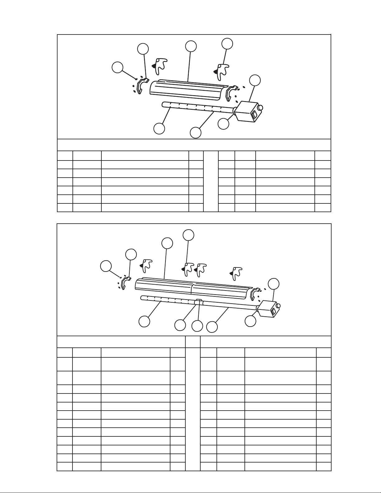
22
Enerco | Calefactor Heatstar ERXL Serie Tubor Instrucciones de uso y manual del usuario
Parts List for MR. Heater Tube Heaters
ERXL-60 80,000 BTU
Item Stock # Description QTY Item Stock# Description QTY
1 F102650XL 60,000BTUNG/Quemadory
cajadecontrol
1 1 F102652XL 80,000BTULP/Quemadorycaja
decontrol
1
F102651XL 60,000BTULP/Quemadory
cajadecontrol
1 F102653XL 80,000BTUNG/Quemadory
cajadecontrol
1
2 F106404XL ERXL-60,/conjuntodetubo20' 1 2 F106404XL 80,000BTU,/conjuntodetubo-20' 1
06413 TubodeI.C.4"D.E..X10' 2 06413 TubodeI.C.4"D.E..X10' 2
3 00418A Reflector 2 3 00418A Reflector 2
4 03445 Deflectordeturbulenciasde10' 1 4 03445 Deflectordeturbulenciasde10' 1
5 14585P Soporte 4 5 14585P Soporte 4
6 02753
Bridadelantera
6 02753
Bridadelantera
7 14 612
Acopledetubería
1 7 14 612
Acopledetubería
1
8 14 616
Encastreparaelacopledetubería
1 8 14 616
Encastreparaelacopledetubería
1
9 0 0 419
Tapadelextremodelreflector
2 9 00 419
Tapadelextremodelreflector
2
10 09369
Ganchosaresorte
8 10 09369
Ganchosaresorte
8
10
9
3
4
5
7
2
6
1
8
ERXL-40
Item Stock # Description QTY Item Stock# Description QTY
1 F102594XL 40,000BTUNG/Quemadorycajadecontrol 1 5 14585P Soporte 4
1 F102595XL 40,000BTULP/Quemadorycajadecontrol 1 6 02753
Bridadelantera
1
2 F106408XL
conjuntodetubo-40'
1 7 0 0 419
Tapadelextremodelreflector
2
06413 TubodeI.C.4"D.E..X10' 2 8 09369
Ganchosaresorte
8
3 00418A Reflector 2
4 03446 Deflectordeturbulenciasde9' 1
1
2
3
6
5
8
4
7
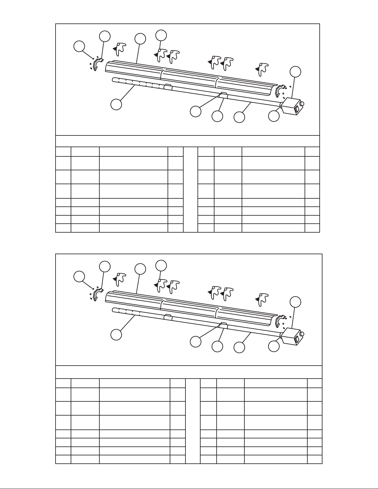
23
Instrucciones de uso y manual del usuarioEnerco | Calefactor Heatstar ERXL Serie Tubor
1
6
2
7
8
4
10
9
3
5
80,000 BTU
Item Stock # Description QTY Item Stock# Description QTY
1 F102652XL 80,000BTUNG/Quemadory
cajadecontrol
1 6 02753
Bridadelantera
1
F102653XL 80,000BTULP/Quemadory
cajadecontrol
1 7 14 612
Acopledetubería
2
2 F106405XL 80,000BTU,/conjuntode
tubo-30'
1 8 14 616
Encastreparaelacoplede
tubería
2
06413 TubodeI.C.4"D.E..X10' 3 9 0 0 419
Tapadelextremodelreflector
2
3 00418A Reflector 3 10 09369
Ganchosaresorte
8
4 03445 Deflectordeturbulenciasde10' 1
5 14585P Soporte 6
1
6
2
7
8
4
10
9
3
5
100,000 BTU
Item Stock # Description QTY Item Stock# Description QTY
1 F102654XL 100,000BTUNG/Quemadory
cajadecontrol
1 6 02753
Bridadelantera
1
F102655XL 100,000BTULP/Quemadorycaja
decontrol
1 7 14 612
Acopledetubería
2
2 F106401XL 100,000BTU/conjuntode
tubo-30'
1 8 14 616
Encastreparaelacoplede
tubería
2
06413 TubodeI.C.4"D.E..X10' 3 9 0 0 419
Tapadelextremodelreflector
2
3 00418A Reflector 3 10 09369
Ganchosaresorte
8
4 03447 Deflectordeturbulenciasde5' 1
5 14585P Soporte 4
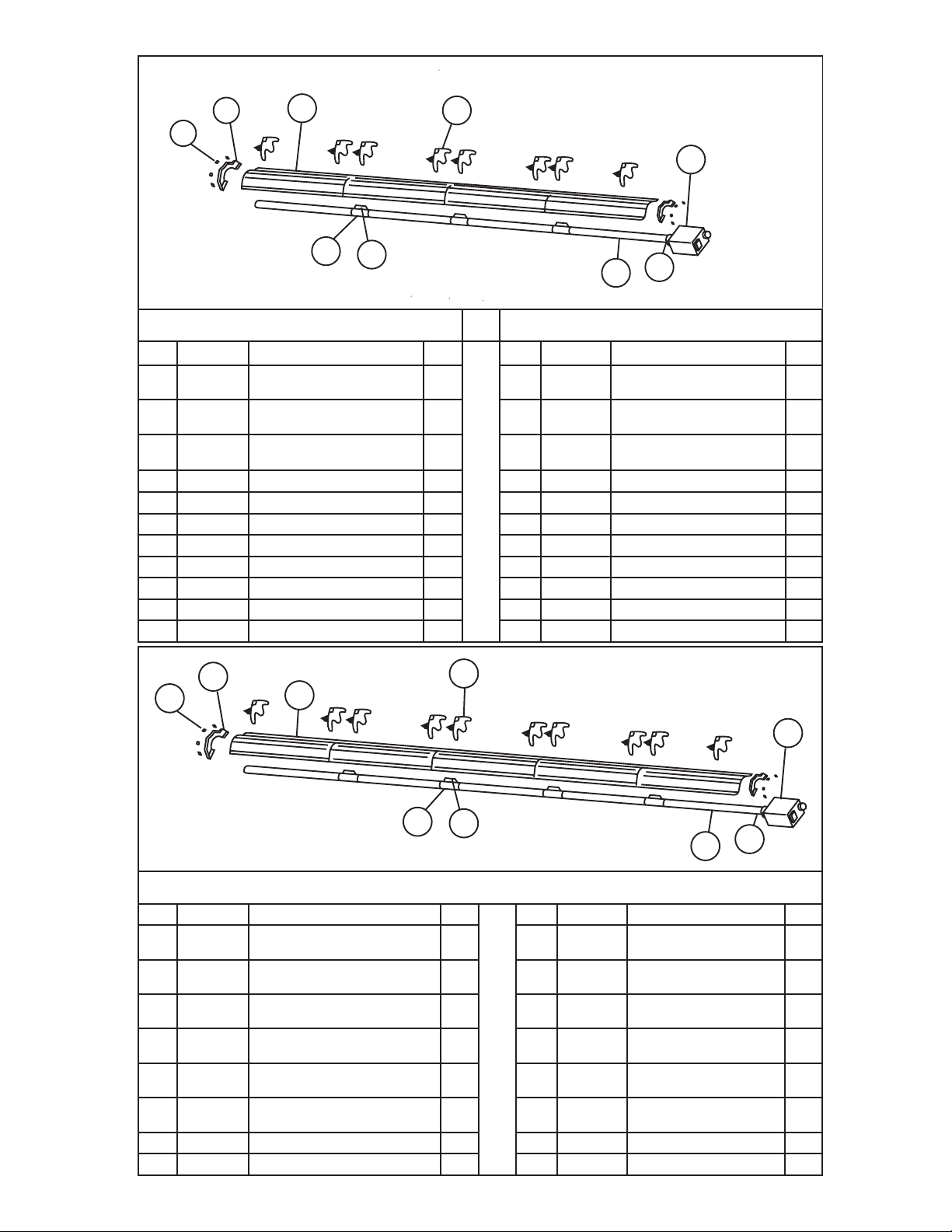
24
Enerco | Calefactor Heatstar ERXL Serie Tubor Instrucciones de uso y manual del usuario
100.000 BTU
125,000 BTU
Item Stock # Description QTY Item Stock# Description QTY
1 F102654XL 100,000BTUNG/Quemadory
cajadecontrol
1 1 F102656XL 125,000BTUNG/Quemadory
cajadecontrol
1
F102655XL 100,000BTULP/Quemadory
cajadecontrol
1 F102657XL 125,000BTULP/Quemadory
cajadecontrol
1
2 F106406XL 100,000BTU/conjuntode
tubo-40'
1 2 F106406XL 125,000BTU/TubeSet-40' 1
06413 TubodeI.C.4"D.E..X10' 4 06413 TubeH.E.4"O.D.X10' 4
6 02753
Bridadelantera
1 3 02753
Bridadelantera
1
4 14 612
Acopledetubería
1 4 14 612 Acopledetubería 1
5 14 616
Encastreparaelacopledetubería
1 5 14 616
Encastreparaelacopledetubería
1
6 00418A Reflector 4 6 00418A Reflector 4
7 14585P Soporte 8 7 14585P Soporte 8
8 0 0 419
Tapadelextremodelreflector
2 8 00 419
Tapadelextremodelreflector
2
9 09369
Ganchosaresorte
8 9 09369
Ganchosaresorte
8
8
9
6
7
1
3
2
4
5
125,000 BTU / 150,000 BTU / 175,000 BTU
Item Stock # Description QTY Item Stock# Description QTY
1 F102656XL 125,000BTUNG/Quemadorycaja
decontrol
1 3 02753
Bridadelantera
1
1 F102657XL 125,000BTULP/Quemadorycaja
decontrol
1 4 14 612
Acopledetubería
2
1 F102658XL 150,000BTUNG/Quemadorycaja
decontrol
1 5 14 616
Encastreparaelacoplede
tubería
2
1 F102659XL 150,000BTULP/Quemadorycaja
decontrol
1 6 00418A Reflector 5
1 F102660XL 175,000BTUNG/Quemadorycaja
decontrol
1 7 14585 Soporte 10
1 F102661XL 175,000BTULP/Quemadorycaja
decontrol
1 8 00 419
Tapadelextremodelreflector
2
2 F106407XL conjuntodetubo-50' 1 9 09369
Ganchosaresorte
8
06413 TubodeI.C.4"D.E..X10' 3
1
3
2
7
5
4
6
9
8
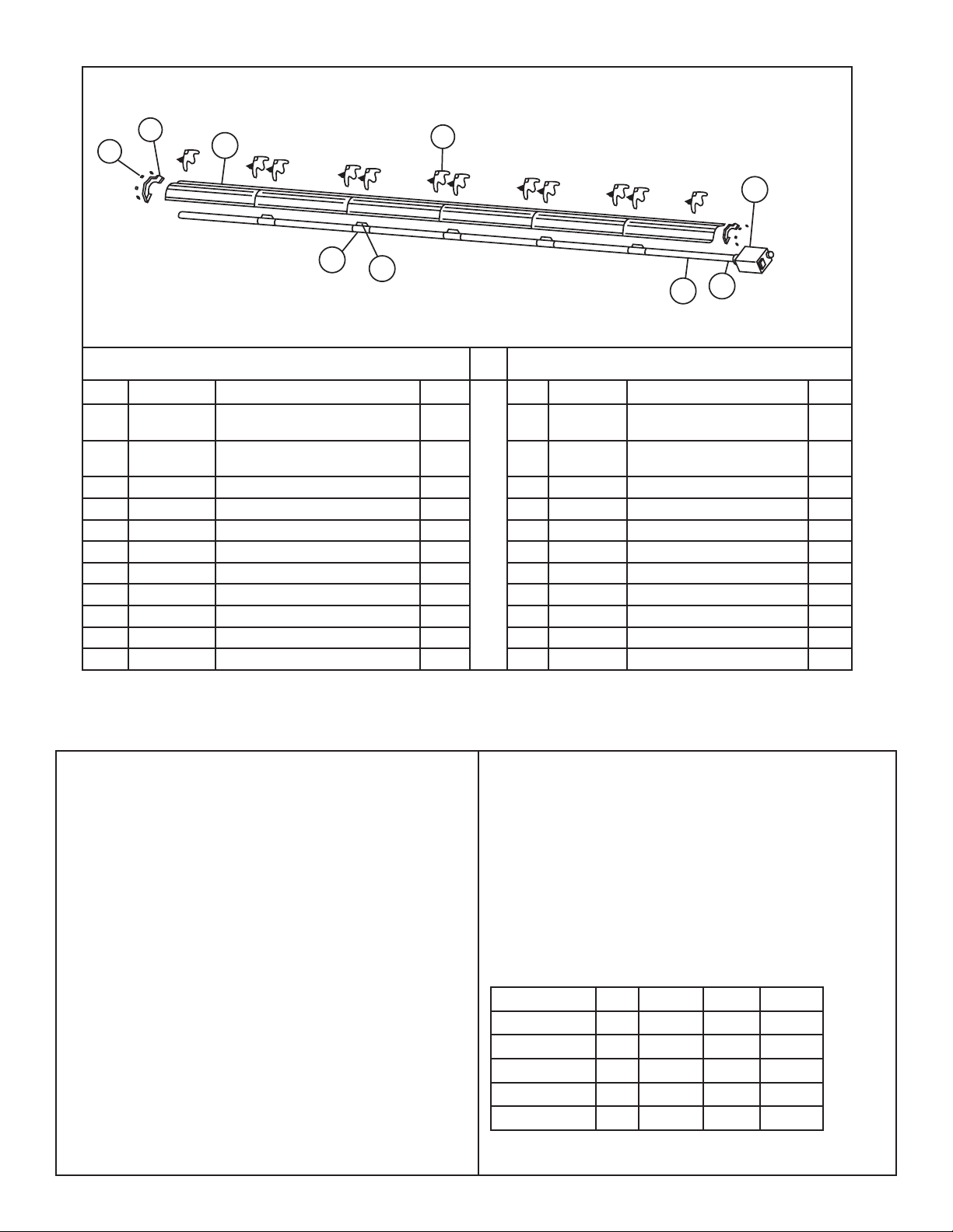
25
Instrucciones de uso y manual del usuarioEnerco | Calefactor Heatstar ERXL Serie Tubor
1
2
3
7
6
4
5
9
8
150,000 BTU 175,000 BTU
Item Stock # Description QTY Item Stock# Description QTY
1 F102658XL 150,000BTUNG/Quemadorycaja
decontrol
1 1 F102660XL 175,000BTUNG/BRN&Cont
Box
1
1 F102659XL 150,000BTULP/Quemadorycajade
control
1 1 F102661XL 175,000BTULP/BRN&Cont
Box
1
2 F106403XL conjuntodetubo-60' 1 2 F106403XL TubeSet-60' 1
06413 TubodeI.C.4"D.E..X10' 6 06413 TubeH.E.4"O.D.X10' 6
3 02753
Bridadelantera
1 3 02753
Bridadelantera
1
4 14 612 Acopledetubería 5 4 14 612
Acopledetubería
5
5 14 616
Encastreparaelacopledetubería
5 5 14 616
Encastreparaelacopledetubería
5
6 00418A Reflector 6 6 00418A Reflector 6
7 14585P Soporte 12 7 14585P Soporte 12
8 0 0 419
Tapadelextremodelreflector
2 8 00 419
Tapadelextremodelreflector
2
9 09369
Ganchosaresorte
8 9 09369
Ganchosaresorte
8
Stock Number Description
10371................................... Termostato24volt
10392................................... Termostato110Volt
17370................................... Juegodecadena
16401.................................. Flexibledeaceroinoxidablede24"
16405.................................. 1/2"x24"3/4"Aceroinoxidable
F106414............................... JuegodeaccesoriostuboUde180
F106415............................... Juegodeaccesorioscodode90
19021 ................................... VentAdaptador
06430.................................. Tapadeventeo
00438.................................. Juegodereflectorlateral
01376 ................................... Juegodedeflector(5')
19031 ................................... Tensorde5/16"-18"
INSTALLATION KITS
F111751…………Installationkitfor20’tubeheater
F111752…………Installationkitfor30’tubeheater
F111753…………Installationkitfor40’tubeheater
F111754…………Installationkitfor50’tubeheater
F111755…………Installationkitfor60’tubeheater
Installationkitincludes:
24-voltthermostat,ventcap,24”stainlesssteelflexiblegas
connector,gasshutoffvalve,andchainkitsrequiredtohangheater.
CONVERSION KITS
60,000 BTU
11732 LPTONG 117 33 NGTOLP
80,000 BTU
1173 4 LPTONG 117 3 5 NGTOLP
100,000 BTU
1173 6 LPTONG 117 37 NGTOLP
125,000 BTU
1173 8 LPTONG 117 3 9 NGTOLP
150,000 BTU
1174 0 LPTONG 11741 NGTOLP
175,000 BTU
1173 0 LPTONG 117 31 NGTOLP
ACCESSORY PARTS LIST
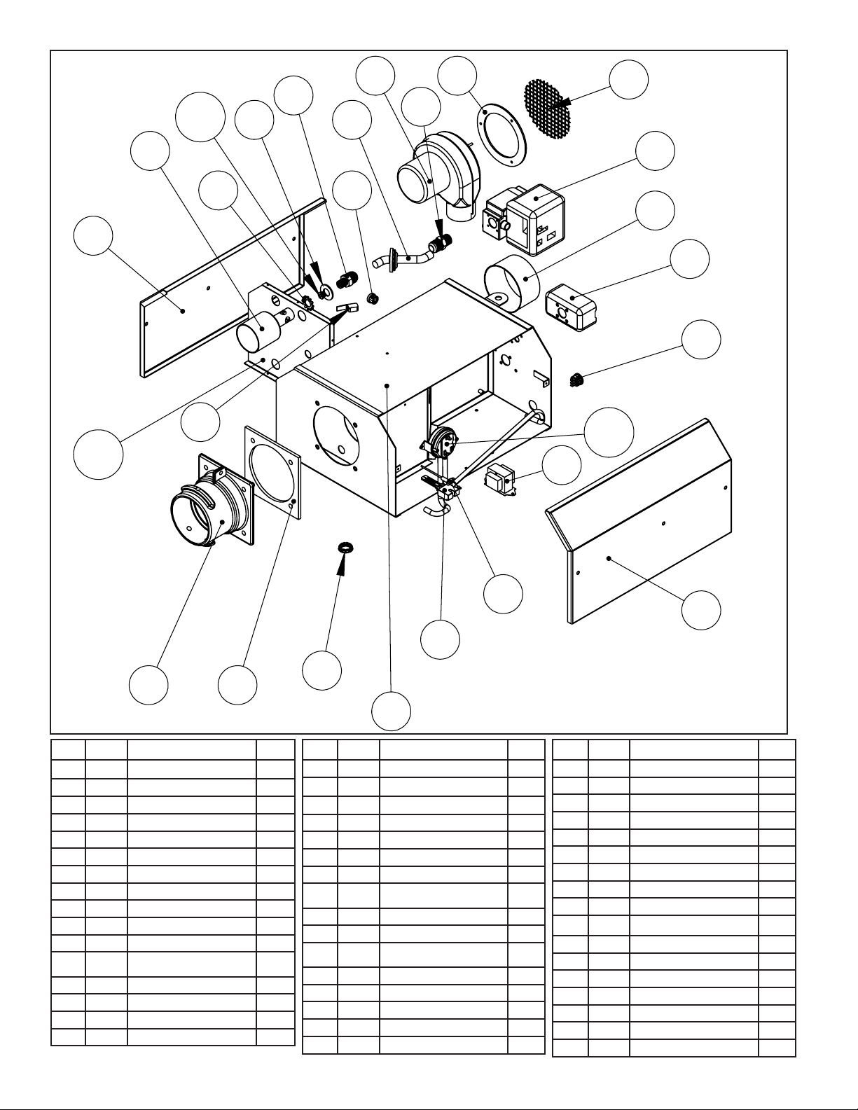
26
Enerco | Calefactor Heatstar ERXL Serie Tubor Instrucciones de uso y manual del usuario
1
2
3
6
5
4
Art. Parte# Descripción
CANT.
17 05502XL 80KPLACADEAIRE 1
18 05501XL 100KPLACADEAIRE 1
19 05500XL 125KPLACADEAIRE 1
20 05503XL 150KPLACADEAIRE 1
21 05508XL 175KPLACADEAIRE 1
22A 00016 HONEYWELLVÁLVULADEGAS(NG) 1
22B 00017 HONEYWELLVÁLVULADEGAS(LP) 1
23 0275 8
ACOPLEDESALIDADEVÁLVULA
DEGAS
1
24 17379
MÚLTIPLEDEGASCONARANDELA
1
25 02720
AISLADORDE2TERMINALES
1
26 98541
ARANDELAPLANADELSOPORTEDE
ORIFICIO
1
27 05794 40KORIFICIO(NG) 1
28 05749 40KORIFICIO(LP) 1
29 05726 60KORIFICIO(NG) 1
30 05744 60KORIFICIO(LP) 1
31 05718 80KORIFICIO(NG) 1
Art. Parte# Descripción
CANT.
32 05737 80KORIFICIO(LP) 1
33 0 5712 100KORIFICIO(NG) 1
34 05733 100KORIFICIO(LP) 1
35 05703 125KORIFICIO(NG) 1
36 05730 125KORIFICIO(LP) 1
37 05796 150KORIFICIO(NG) 1
38 05728 150KORIFICIO(LP) 1
39 05799 175 ORIFICIO(NG) 1
40 05725 175KORIFICIO(LP) 1
41 98547
ARANDELADENTADAEXTERNA
1
42 02371
TAZADELQUEMADOR
1
43 10391A
INTERRUPTORDEPUERTA
1
44 02721
AISLADORDE2TERMINALES
1
45 07376
SOPLADOR
1
46 12395
JUNTADELSOPLADOR
1
47 02718
FILTRODELSOPLADOR
1
48 02795
VENTANADEOBSERVACIÓN
1
Art. Parte# Descripción
CANT.
1 02716XL
GABINETE
1
2 02725XL
CUBIERTALATERALDECONTROL
1
3 02749XL
CUBIERTALATERALDELMOTOR
1
4 12397
JUNTADELABRIDADELANTERA
1
5 02753
BRIDADELTUBODELANTERO
1
6 08364A
TRANSFORMADOR
1
7 02836 40KINTERRUPTORDEPRESIÓN 1
8 10 413 A 60-125KINTERRUPTORDEPRESIÓN 1
9 10 414A 150K-175KINTERRUPTORDEPRESIÓN 1
10 02730
BARRADELSENSORDELLAMA
1
11 02765
SUPERFICIECALIENTEDEIGNICIÓN
1
12 02847
AISLADORDE3TERMINALESDEL
TERMOSTATO
1
13 99101
CAJADEEMPALMESELÉCTRICOS
1
14 02747
BRIDADEENTRADADELSOPLADOR
1
15 05510XL 40KPLACADEAIRE 1
16 06606XL 60KAIRPLATE 1
40
41
42
43
44
45 46
47
48
7-9
10
11
12
13
14
15-
21
22
23
24
25
26
27-

27
Instrucciones de uso y manual del usuarioEnerco | Calefactor Heatstar ERXL Serie Tubor
NOTAS:
28
Enerco | Calefactor Heatstar ERXL Serie Tubor Instrucciones de uso y manual del usuario
ADVERTENCIA:
USESOLAMENTEPARTESDEREPUESTODELFABRICANTE.ELUSODECUALQUIER
OTRAPARTEPODRÍACAUSARHERIDASOLAMUERTE.LASPARTESDEREPUESTO
ESTÁNDISPONIBLESÚNICAMENTEENLAFÁBRICAYDEBENSERINSTALADASPOR
UNAAGENCIADESERVICIOCALIFICADA.
POR INFORMACIÓN ACERCA DE REPARACIONES O PARTES:
Llameasutécnicolocaldecalefacciónodistribuidor.
POR INFORMACIÓN ADICIONAL:
Llamesincargoal866-447-2194-www.Mr.Heaterbyenerco.com
Nuestrohorariodetrabajoesde08:00a.m.AMa5:00PM,delunesaviernes,hora
deleste.
Tengaamanosunúmerodemodelo,númerodeserieyfechadecompra.
GARANTÍA LIMITADA
Lacompañíagarantizaqueesteproductoestarálibredeimperfeccionesmaterialesydefabricación,bajo
condicionesdeusonormalesyadecuadasdeacuerdoconlasinstruccionesdelaMr.HeaterCompañía,por
unperíodode10añosapartirdelafechadeentregaalcomprador.
•Parainstalarenunlavaderodecochesyenáreasconexposiciónaproductosquímicoscorrosivos,comoel
amoníaco,cloro,etc.,lagarantíaselimitaráa2añosentubosy1añoentodosloscomponentesdemás.
LaMr.HeaterCompañía,segúndecida,repararáoreemplazarálosproductosqueelcompradordevuelva
alafábrica,contransportaciónprepagadadentrodelmencionadoperíododeunañoyquelaCompañía
determinequepresentanimperfeccionesmaterialesodefabricación.
Sialgunadelaspartesestádañadaosilefaltaalguna,llameanuestroDepartamentodeasistenciaal
clienteal866-447-2194.
DirijatodoslosreclamosdegarantíaalDepartamentodeasistenciaalcliente,Mr.Heater,Inc,4560W.
160THST.,CLEVELAND,OHIO44135.Incluyasunombre,direcciónynúmerotelefónicoensucomunicación
eincluyalosdetallesrelacionadosconelreclamo.Además,infórmenoslafechadelacomprayelnombrey
direccióndelproveedordequienadquiriónuestroproducto.
LoanteriordescribelasresponsabilidadesdelaCompañíaentodasuextensión.Nohayotrasgarantías,
niexplícitasniimplícitas.Específicamente,nohaygarantíasacercadelaadecuaciónparaunpropósito
particularynohaygarantíasdecomerciabilidad.EnningúncasolaCompañíaseráresponsablepor
demorascausadasporimperfecciones,pordañosconsecuentes,niporningúnotrocargodegastosde
ningunanaturalezarealizadosinsuconsentimientoescrito.Elcostodereparaciónoreemplazoserálaúnica
compensaciónporcualquierincumplimientodelagarantía.Nohaygarantíanisederivarágarantíaimplícita
algunadelprocesodecomercializaciónnidelasprácticascomercialescomunes.Estagarantíanoseráválida
paraproductosquehayansidoreparadosoalteradosfueradelafábricaencualquiersentidoqueanuestro
criterioafectesuestadoofuncionamiento.
Algunosestadosnopermitenlaexclusiónolimitacióndedañosincidentalesniconsecuentes,asíquela
limitaciónoexclusiónanteriorpuedenotenervalidezensucaso.EstaGarantíaleotorgaderechoslegales
específicos,yustedpuedetenerotrosderechosquevaríandeunestadoaotro.
Mr.Heater,Inc,4560W.160THST.,CLEVELAND,OHIO44135•866-447-2194
©2016,Mr.Heater,Inc.Todoslosderechosreservados
Mr.Heater,Incsereservaelderechodehacercambiosencualquiermomento,sin
previoaviso,enloscolores,especificaciones,accesorios,materialesymodelos.
INSTRUCCIONES DE USO Y MANUAL DEL USUARIO
ANSI Z83.20b-2011 CSA 2.34b-2011
C
US
110VMODELOS
40,000BTU60,000BTU
80,000BTU 100,000BTU
125,000BTU150,000BTU
175,000BTU