Before using your new product, please read these instructions to prevent any damage.
ASSEMBLY GUIDE
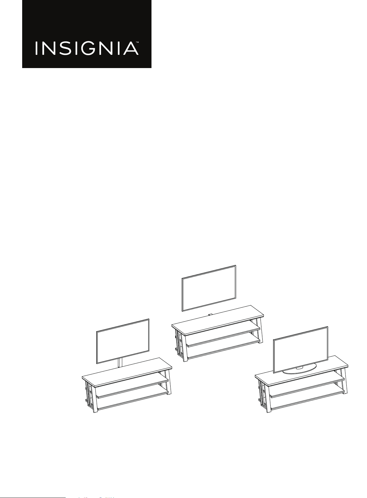
3-in-1 TV Stand
NS-HFTVS3N175

www.insigniaproducts.com
2
Contents
IMPORTANT SAFEGUARDS . . . . . . . . . . . . . . . . . . . . . . . . . . . . . . . . . . . . . . . . . . . . . . . . . . . . . . . . . . . . . . . . . . . . . . . . . . . . 3
Features . . . . . . . . . . . . . . . . . . . . . . . . . . . . . . . . . . . . . . . . . . . . . . . . . . . . . . . . . . . . . . . . . . . . . . . . . . . . . . . . . . . . . . . . . . . . . . 4
Dimensions. . . . . . . . . . . . . . . . . . . . . . . . . . . . . . . . . . . . . . . . . . . . . . . . . . . . . . . . . . . . . . . . . . . . . . . . . . . . . . . . . . . . . . . . . . . . . . . . . . . . . . . 4
Package contents . . . . . . . . . . . . . . . . . . . . . . . . . . . . . . . . . . . . . . . . . . . . . . . . . . . . . . . . . . . . . . . . . . . . . . . . . . . . . . . . . . . . . 5
Parts . . . . . . . . . . . . . . . . . . . . . . . . . . . . . . . . . . . . . . . . . . . . . . . . . . . . . . . . . . . . . . . . . . . . . . . . . . . . . . . . . . . . . . . . . . . . . . . . . . . . . . . . . . . . . 5
Hardware. . . . . . . . . . . . . . . . . . . . . . . . . . . . . . . . . . . . . . . . . . . . . . . . . . . . . . . . . . . . . . . . . . . . . . . . . . . . . . . . . . . . . . . . . . . . . . . . . . . . . . . . . 6
Tools needed . . . . . . . . . . . . . . . . . . . . . . . . . . . . . . . . . . . . . . . . . . . . . . . . . . . . . . . . . . . . . . . . . . . . . . . . . . . . . . . . . . . . . . . . . 7
Assembling your stand. . . . . . . . . . . . . . . . . . . . . . . . . . . . . . . . . . . . . . . . . . . . . . . . . . . . . . . . . . . . . . . . . . . . . . . . . . . . . . . . 8
Mounting the TV using the swivel configuration . . . . . . . . . . . . . . . . . . . . . . . . . . . . . . . . . . . . . . . . . . . . . . . . . . . . . .16
Mounting the TV using the wall-mount configuration . . . . . . . . . . . . . . . . . . . . . . . . . . . . . . . . . . . . . . . . . . . . . . . . .26
Mounting the TV using the tabletop configuration. . . . . . . . . . . . . . . . . . . . . . . . . . . . . . . . . . . . . . . . . . . . . . . . . . . .33
Maintaining your TV stand . . . . . . . . . . . . . . . . . . . . . . . . . . . . . . . . . . . . . . . . . . . . . . . . . . . . . . . . . . . . . . . . . . . . . . . . . . .37
Specifications. . . . . . . . . . . . . . . . . . . . . . . . . . . . . . . . . . . . . . . . . . . . . . . . . . . . . . . . . . . . . . . . . . . . . . . . . . . . . . . . . . . . . . . .37
ONE-YEAR LIMITED WARRANTY . . . . . . . . . . . . . . . . . . . . . . . . . . . . . . . . . . . . . . . . . . . . . . . . . . . . . . . . . . . . . . . . . . . . . .38
www.insigniaproducts.com
3
3-in-1 TV Stand
IMPORTANT SAFEGUARDS
WARNING
CAUTION
The top surface of this stand is designed for use with a product weighing no more than 100 lbs. (45.4 kg) and having a
width that permits it to sit evenly on the stand with no more than a one-inch overhang on each side of the shelf. Use
with products that weigh more than the maximum weight allowed, or with dimensions that extend beyond the
maximum width may result in instability, which may result in injury.
CAUTION
This product contains small items that could be a choking hazard if swallowed. Keep these items away from young
children!
WARNING
Please use your stand correctly and safely. Improper use can cause safety hazards or damage to your furniture or
household items. Carefully read the following chart.
SAVE THESE INSTRUCTIONS
LOOK OUT FOR: WHAT CAN HAPPEN: HOW TO AVOID THE PROBLEM:
• Children climbing on the
stand.
• A child may try to reach a
toy or other object by
climbing on the stand.
• Children will play and be
active near the TV.
• Risk of injury or death.
• A child climbing on the
stand can make it
top-heavy and cause it to
tip over.
• A child playing with a TV
can cause it to tip over.
• Never allow children to climb on or play with
the stand.
• Do not place toys or food on the top shelves.
Children may try to climb to reach them out of
curiosity.
• Improper use of the stand
to support TVs.
• The stand is designed for
use with TVs will specify
the maximum weight
rating and recommended
size of the TVs it will safely
support.
• Risk of injury or death.
• TVs can be very heavy.
Note, older CRT TVs tend
to be unbalanced and
prone to tipping forward.
• A TV must only be set on furniture specifically
designed to support a television.
• Never use a TV that exceeds the weight ratings
or size guidelines specified for the stand.
• Improperly moving the
stand.
• The stand can tip over or
break if improperly
moved.
• Risk of injury.
• Unload shelves from the top to the bottom
before moving the stand.
• Do not push the stand, especially on a carpeted
floor. Have a friend help you lift the item and set
it in place.
• Do not lift the stand using the top shelf. Lift
from the frame or leg assembly.
• Remove the TV before moving the TV stand.
• The TV/stand assembly
tipping forward.
• Risk of injury.
• Top-heavy furniture can
tip over.
• The TV and stand could
be damaged.
• Use the tipping restraint hardware provided
and install it properly.
Some steps are more easily
handled with two adults.
www.insigniaproducts.com
4
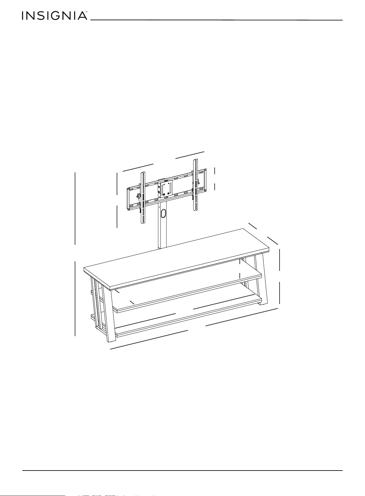
Features
• 3-in-1 display system lets you tilt (5° up/11° down) or swivel (45° left/right) your TV to find the best view
• Sturdy mount supports most flat screen TVs up to 75 in. (190.5 cm) and 100 lbs. (45.4 kg)
• Three open shelves provide space for cable boxes, Blu-ray players, game consoles and more
• Textured wood grain laminate in a neutral gray looks great in any living room
• Anti-tip hardware protects children and pets from accidental tip-overs
• Compatible VESA configurations:
• 200 × 200
• 200 × 300
• 300 × 300
• 400 × 200
• 400 × 300
• 400 × 400
• 600 × 400
Dimensions
57.7 in.
(146.7 cm)
32 in.
(81.3 cm)
22.3 in. (56.5 cm)
20 in. (50.8 cm)
8.8 in. (22.2 cm)
8 in. (20.5 cm)
58.9 in.
(149.7 cm)
18.4 in. (46.8 cm)
65 in.
(165.1 cm)
21 in. (53.3 cm)
www.insigniaproducts.com
5
3-in-1 TV Stand
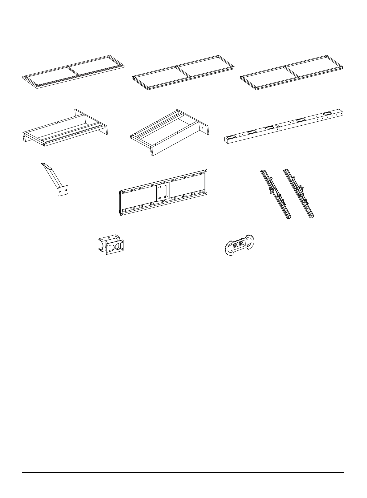
Package contents
Parts
A Top shelf frame (1)
B Middle shelf (1)
C Bottom shelf (1)
D Left side frame (1)
E Right side frame (1)
F Spine assembly (1)
G Top shelf support (1)
H Swivel bracket (1)
I Mounting frame (1)
J TV bracket (2)
K Cable clip (2)
www.insigniaproducts.com
6
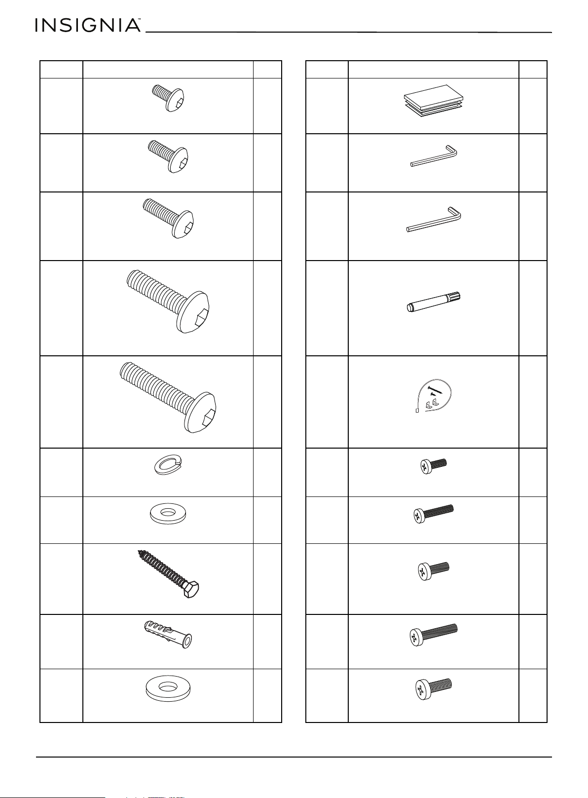
Hardware
LABEL STAND PART QTY. LABEL STAND PART QTY.
L 4 V 1
M 13 W 2
N 4 X 1
O 12 Y 1
P 2 Z 1
Q 29 AA 4
R 29 BB 4
S 4 CC 4
T 4 DD 4
U 4 EE 4
Bolt 1/2" (12.7 mm)
Plastic end cap
Bolt 5/8" (15.9 mm)
Hex key 4 mm
Bolt 1"’ (25.4 mm)
Hex key 4.8 mm
Bolt 1 1/4" (31.6 mm)
Touch-up pen
Bolt 1 3/4" (44.5 mm)
Tipping restraint hardware kit
Lock washer
Bolt M4 × 12 mm
Flat washer
Bolt M4 × 30 mm
Lag bolt
Bolt M5 × 12 mm
Concrete anchor
Bolt M5 × 30 mm
Large flat washer
Bolt M6 × 12 mm
www.insigniaproducts.com
7
3-in-1 TV Stand
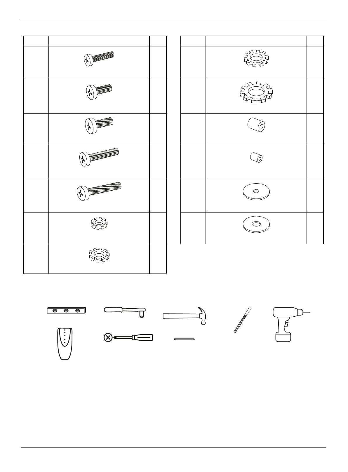
Hardware (continued)
Tools needed
LABEL STAND PART QTY. LABEL STAND PART QTY.
FF 4 MM 4
GG 4 NN 4
HH 4 OO 4
II 4 PP 4
JJ 4 QQ 4
KK 4 RR 4
LL 4
Bolt M6 × 35 mm
Lock washer M6
Bolt M8 × 16 mm
Lock washer M8
Bolt M8 × 20 mm
Large spacer
Bolt M8 × 40 mm
Small spacer
Bolt M8 × 50 mm
Flat washer M4/M5
Lock washer M4
Flat washer M6/M8
Lock washer M5
Phillips screwdriver
Edge-to-edge stud finder
Level
Socket wrench
Hammer
Pencil
1/8” drill bit (for tipping
restraint)
3/16” wood drill bit
or
7/16” masonry drill bit
Power drill
www.insigniaproducts.com
8
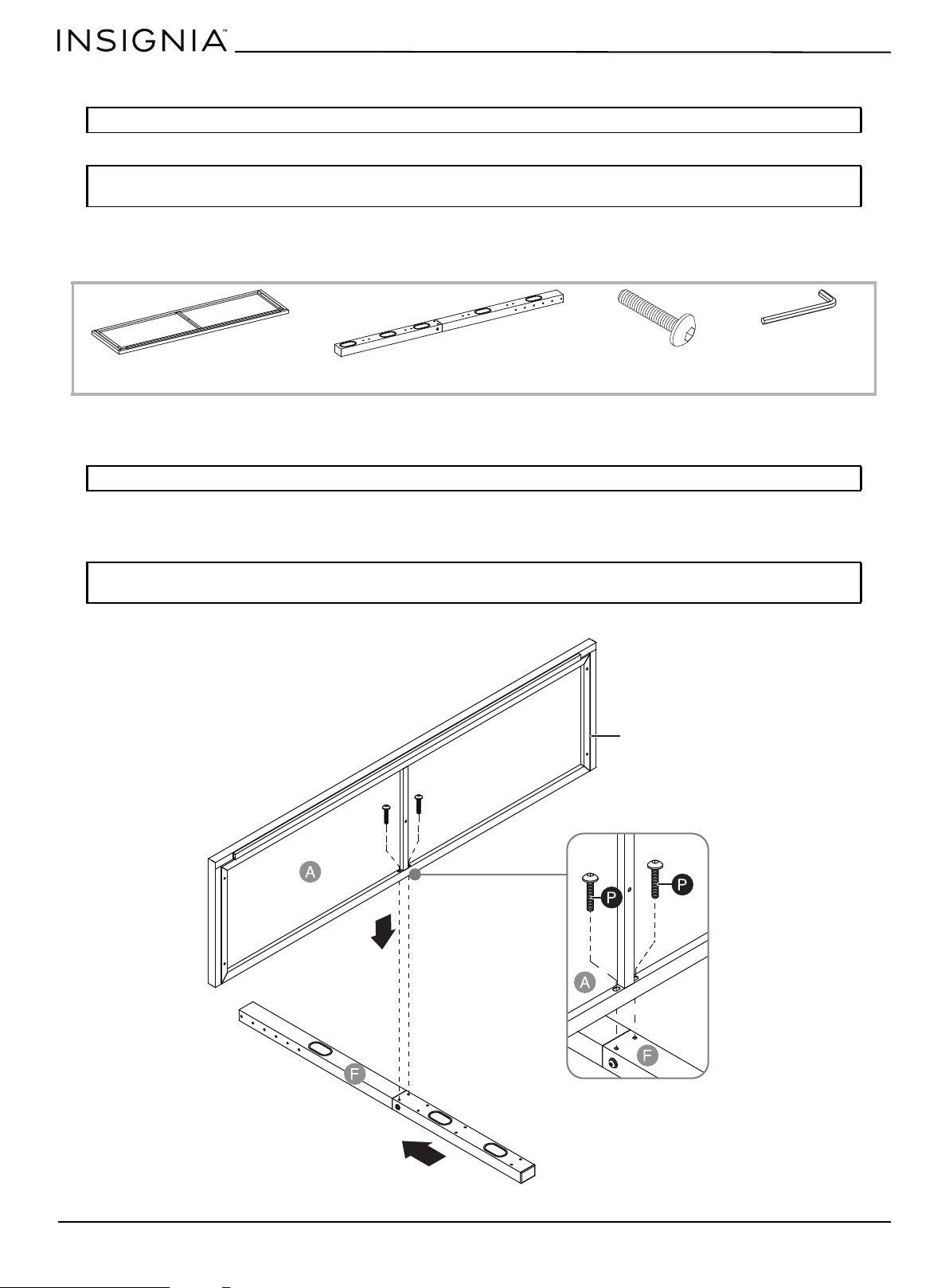
Assembling your stand
STEP 1: Attach the top panel to the spine
You need:
1 Align the top shelf frame (A) at a 90° angle to the spine assembly (F). Make sure that the drilled holes on the frame align
with the threaded holes on the spine.
2 Insert two 1 3/4" bolts (P) through the drilled holes on the frame (A), then screw them into the holes on the spine
assembly with the 4 mm hex key (W).
Tip: Assemble your stand on a carpeted floor or the empty TV stand carton to avoid scratching it.
Note: Do not fully tighten all bolts until you finish assembling all of the parts. After assembly, go back and fully
tighten all bolts. This will make the assembly easier.
Note: The metal frame faces the floor when you turn your stand upright.
Note: Do not fully tighten all bolts until you finish assembling all of the parts. After assembly, go back and fully
tighten all bolts. This will make the assembly easier.
A Top shelf frame (1)
F Spine assembly (1)
P Bolt 1 3/4" (2)
W 4 mm hex key (1)
Metal frame
www.insigniaproducts.com
9
3-in-1 TV Stand
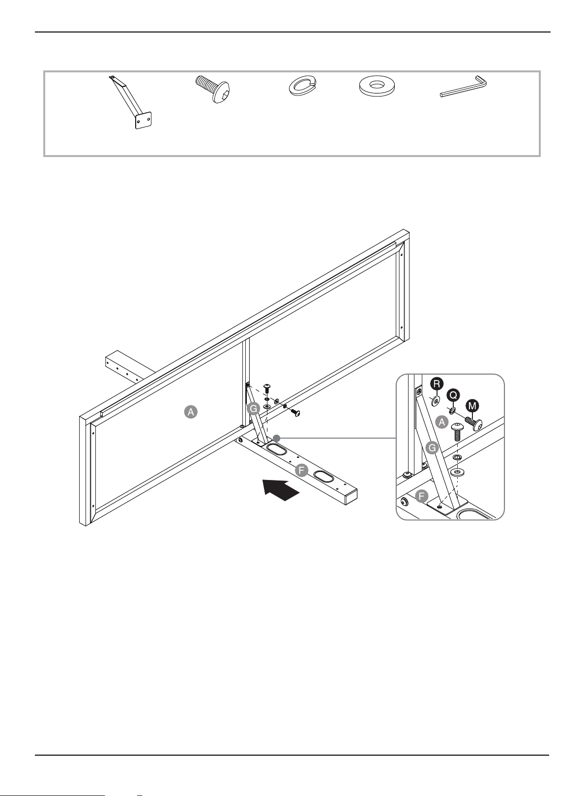
STEP 2: Attach the top shelf support to the top panel and spine
You need:
1 Align the top shelf support (G) with the center of the top shelf frame (A).
2 Place a flat washer (R), then a lock washer (Q) over the hole in the top of the shelf support and in the two holes on the
bottom of the shelf support.
3 Insert a 5/8" bolt (M) through each sets of washers, then tighten the bolts with the 4 mm hex key (W).
G Top shelf support (1)
M 5/8" bolt (3)
W 4 mm hex key (1)
Q Lock washer (3)
R Flat washer (3)
www.insigniaproducts.com
10
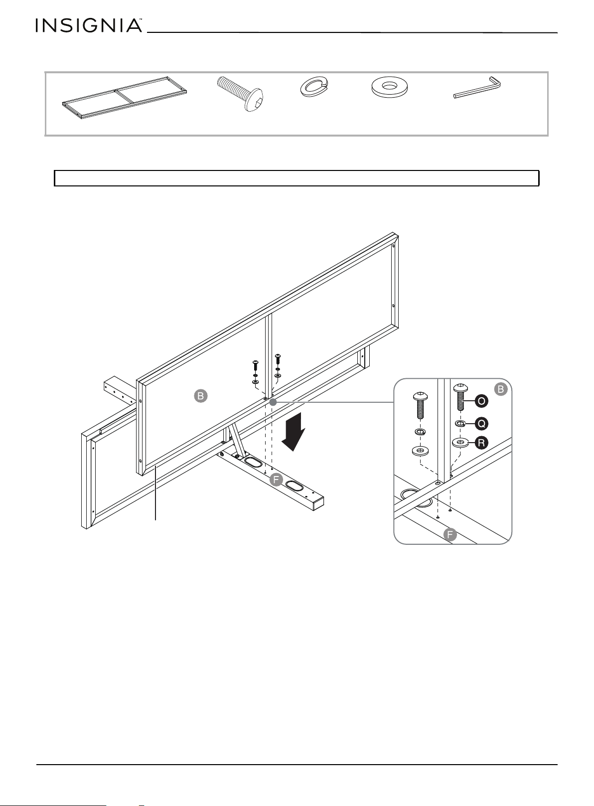
STEP 3: Attach the middle shelf to the spine
You need:
1 Place flat washers (R), then lock washers (Q) over the two drilled holes on the middle shelf (B).
2 Insert 1 1/4" bolts (O) through the washers and into the two threaded holes in the middle of the spine (F). Tighten the
bolts with the 4 mm hex key (W).
Note: The metal frame faces the floor when you turn your stand upright.
W 4 mm hex key (1)
Q Lock washer (2)
R Flat washer (2)
O 1 1/4" bolt (2)
B Middle shelf (1)
Metal frame
www.insigniaproducts.com
11
3-in-1 TV Stand
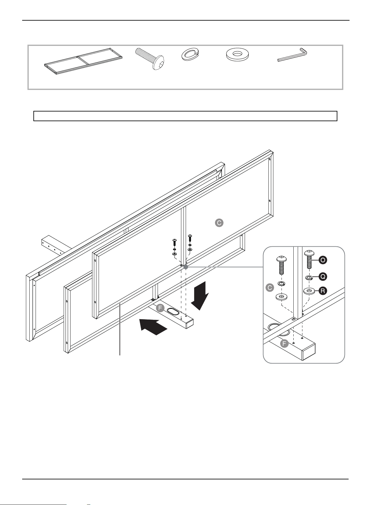
STEP 4: Attach the bottom shelf to the spine
You need:
1 Place flat washers (R), then lock washers (Q) over the two drilled holes on the bottom shelf (C).
2 Insert 1 1/4" bolts (O) through the washers and into the two threaded holes on the outer edge of the spine (F). Tighten
the bolts with the 4 mm hex key (W).
Note: The metal frame faces the floor when you turn your stand upright.
C Bottom shelf (1)
W Hex key 4 mm (1)
Q Lock washer (2)
R Flat washer (2)
O 1 1/4" bolt (2)
Metal frame
www.insigniaproducts.com
12
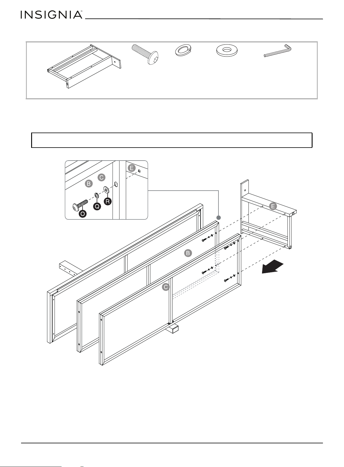
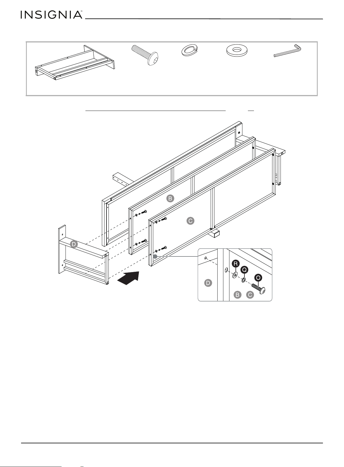
STEP 5: Align and attach the right side frame to the shelves
You need:
1 Place flat washers (R), then lock washers (Q) over the four drilled holes on the inside of the lower shelves (B and C).
2 Insert 1 1/4" bolts (O) through the washers and into the four threaded holes on the right side frame (E). Tighten the
bolts with the 4 mm hex key (W).
Note: Make sure that the mounting holes on the top rail of the right side frame (E) overlap the threaded holes
underneath the top shelf frame (A) correctly.
W Hex key 4 mm (1)
Q Lock washer (4)
R Flat washer (4)
O 1 1/4" bolt (4)
E Right side frame (1)
www.insigniaproducts.com
13
3-in-1 TV Stand
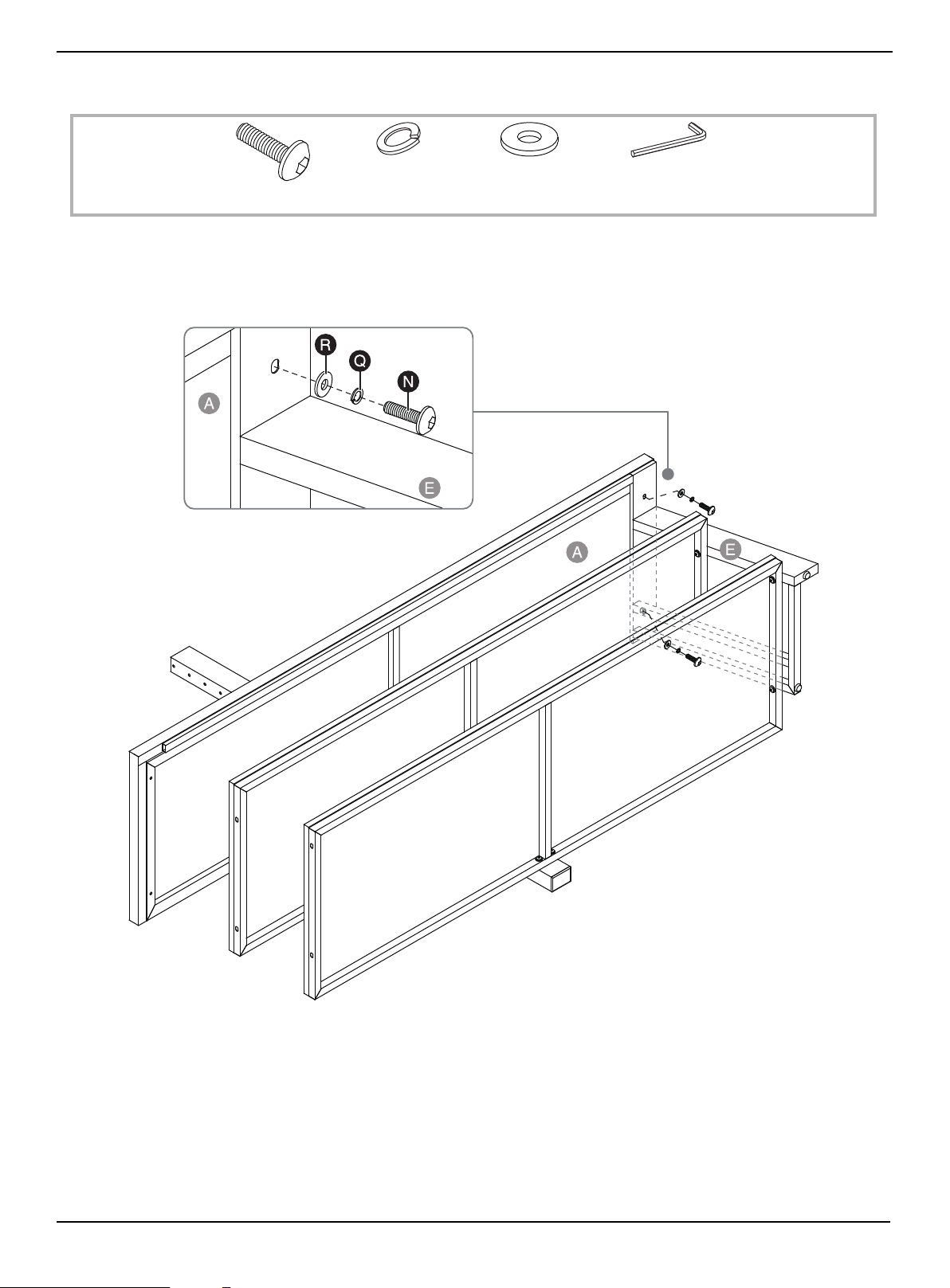
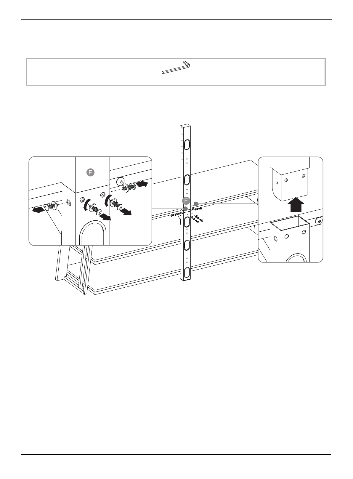
STEP 6: Attach the right side frame to the top panel
You need:
1 Place flat washers (R), then lock washers (Q) over the two drilled holes on the inside of the top rail of right side
frame (E).
2 Insert 1" bolts (N) through the washers and into the two threaded holes on the top panel (A). Tighten the bolts with the
4 mm hex key (W).
W Hex key 4 mm (1)
Q Lock washer (2)
R Flat washer (2)
N 1" bolt (2)
www.insigniaproducts.com
14
STEP 7: Attach the left side frame to the shelves
You need:
• Follow the steps in STEP 5: Align and attach the right side frame to the shelves on page 12 to attach the left side
frame (D) to the lower shelves (B and C).
W Hex key 4 mm (1)
Q Lock washer (4)
R Flat washer (4)
D Left side frame (1)
O 1 1/4" bolt (4)
www.insigniaproducts.com
15
3-in-1 TV Stand
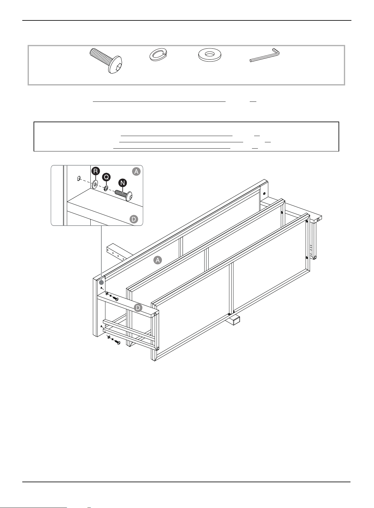
STEP 8: Fasten the left side frame to the top panel
You need:
1 Follow the steps in STEP 6: Attach the right side frame to the top panel on page 13 to attach the left side frame (D) to
the top shelf frame (A).
2 Stand the assembled frame upright.
Note:
• For swivel stand assembly, go to Mounting the TV using the swivel configuration on page 16.
• For wall-mount assembly, go to Mounting the TV using the wall-mount configuration
on page 26.
• For table top assembly, go to Mounting the TV using the tabletop configuration
on page 33.
W Hex key 4 mm (1)
Q Lock washer (2)
R Flat washer (2)
N 1" bolt (2)
www.insigniaproducts.com
16
Mounting the TV using the swivel configuration
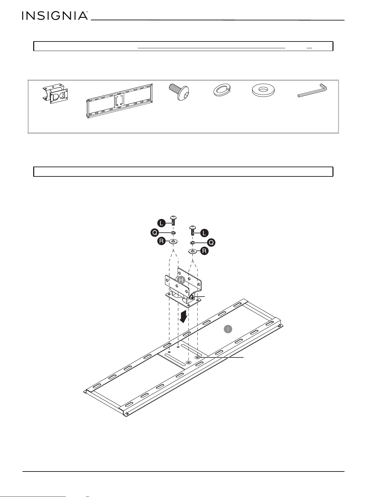
STEP 1: Attach the swivel bracket to the mounting frame
You need:
1 Align the four mounting holes on the swivel bracket (H) with the holes on the back side of the mounting frame (I). Make
sure that the hex nut on the swivel bracket and the two recessed holes on the mounting frame point in the same
direction.
2 Place a flat washer (R), then a lock washer (Q) over each of the mounting holes on the back of the swivel bracket (H).
3 Insert a 1/2" bolt (L) through the washers and into each of the threaded holes on the mounting frame (I).
4 Tighten the bolts with the 4 mm hex key (W).
Note: If you are wall-mounting the TV, go to STEP 4: Select the correct bolts, washers, and spacers for your TV on page 19.
Note: The hex nut and recessed holes point in the same direction.
H Swivel bracket (1)
I Mounting frame (1)
W Hex key 4 mm (1)
Q Lock washer (4)
R Flat washer (4)
L 1/2" bolt (4)
Hex nut
Recessed holes
www.insigniaproducts.com
17
3-in-1 TV Stand
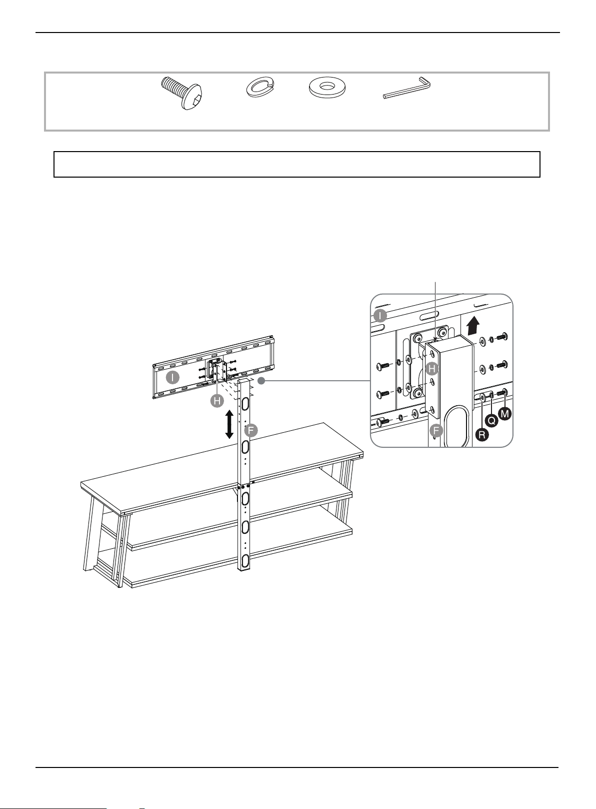
STEP 2: Attach the swivel bracket assembly to the spine
You need:
1 Place a flat washer (R), then lock washer (Q) over one of the holes on the side of the swivel bracket.
2 Insert a 5/8" bolt (M) through the washers and into the threaded hole on the spine assembly (F).
3 Repeat steps 1 through 2 for the five remaining holes.
4 Tighten the bolts with the 4 mm hex key (W).
Note: The upper spine provides four height options for your TV. Based on your TV size, adjust the swivel bracket (H)
to the best height to offer optimum viewing.
W Hex key 4 mm (1)
Q Lock washer (6)
R Flat washer (6)
M 5/8" bolt (6)
The pivot bolt head
is located at the top
www.insigniaproducts.com
18
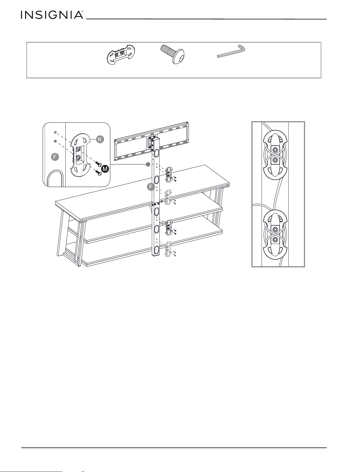
STEP 3: Attach the cable clips
You need:
1 Align a cable clip with two of four possible locations on the spine assembly (F), then insert two 5/8" bolts (M) through
the cable clip and into the spine assembly.
2 Repeat for the other cable clip.
3 Tighten the bolts with the 4 mm hex key (W).
K Cable clip (2)
M 5/8" bolt (4)
W Hex key 4 mm (1)
Cables wrapped on cable clips

www.insigniaproducts.com
19
3-in-1 TV Stand
STEP 4: Select the correct bolts, washers, and spacers for your TV
If you are in doubt about which size bolt to use, try one of the bolts in one of the four Vesa mounting holes on the back of
your TV. A bolt that is too large will not fit in the hole at all, but make sure that the bolt size you choose is not too loose. It
should grip the hole threads evenly and not wobble. After you determine which size bolts to use, go to the next step.
M4 hardware assembly:
•M4 × 12 mm bolts (AA) top screw holes
•M4 × 30 mm bolts (BB) bottom screw holes
• M4 lock washers (KK)
• M4/M5 flat washers (QQ)
• Small spacers (PP)
M5 hardware assembly:
•M5 × 12 mm bolts (CC) top screw holes
•M5 × 30 mm bolts (DD) bottom screw holes
• M5 lock washers (LL)
• M4/M5 flat washers (QQ)
• Small spacers (PP)
M6 hardware assembly:
•M6 × 12 mm bolts (EE) top screw holes
•M6 × 35 mm bolts (FF) bottom screw holes
• M6 lock washers (MM)
• M6/M8 flat washers (RR)
• Large spacers (OO)
M8 hardware assembly:
•M8 × 16 mm bolts (GG) or M8 × 20 mm bolts (HH) top screw holes
• M8 x 40 mm bolts (II) or M8 × 50 mm bolts (JJ) bottom screw holes
• M8 lock washers (NN)
• M6/M8 flat washers (RR)
• Large spacers (OO)
www.insigniaproducts.com
20
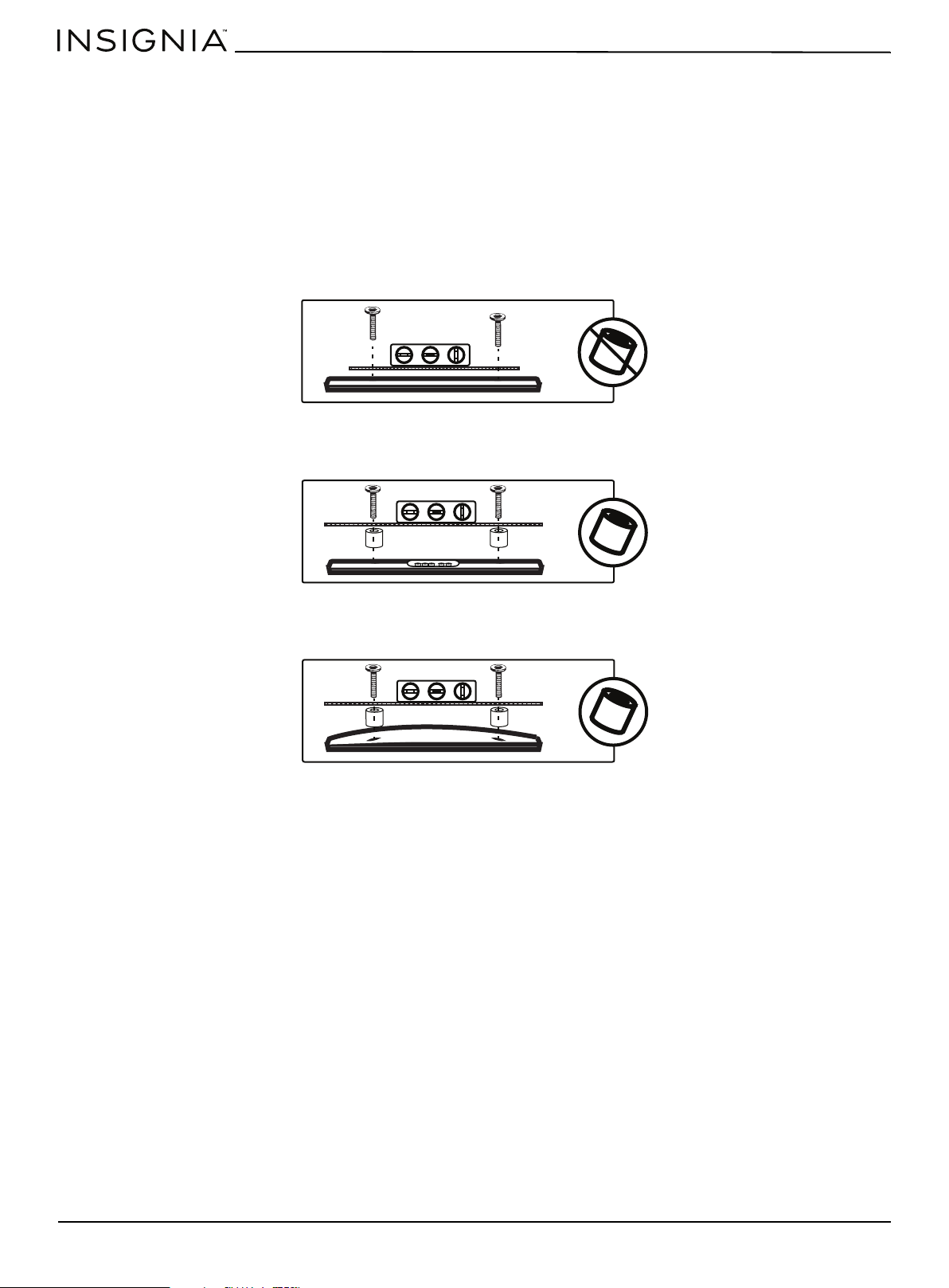
STEP 5: Determine whether your TV has a flat back or an irregular or obstructed back or a curved
screen
1 Carefully place your TV screen face-down on a cushioned, clean surface to protect the screen from damages and
scratches.
2 If your TV has a table-top stand attached, remove the stand. See the documentation that came with your TV for
instructions.
3 Lay the TV brackets, oriented vertically, on the back of your TV.
4 Align the screw holes in the TV brackets with the mounting screw holes on your TV.
5 Identify which type of back your TV has:
• Flat back: The brackets lay flush against the back of your TV and do not block any jacks. You do not need spacers when
assembling the wall mount.
• Obstructed back: The brackets block one or more of the jacks on the back of your TV. You need spacers when
assembling the wall mount.
• Irregularly-shaped back: There is a gap between a bracket and some part of the back of your TV. You need spacers
when assembling the wall mount.
6 Remove the TV brackets.
www.insigniaproducts.com
21
3-in-1 TV Stand
STEP 6: Option 1 - Mounting brackets on a TV with a flat back
You need:
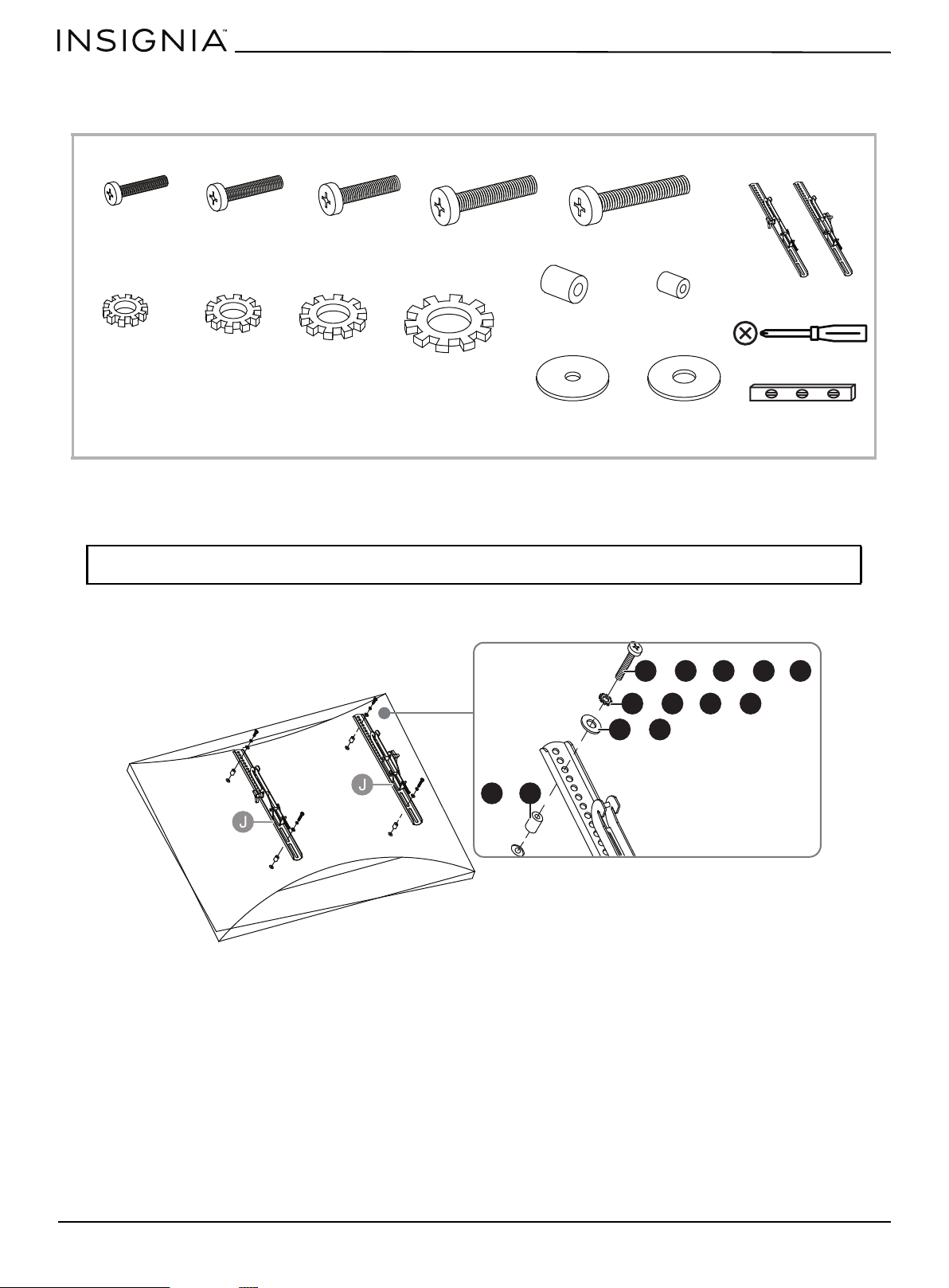
1 Insert the selected bolts through the washers and correct mounting holes on the TV brackets (J), then finger tighten
them into the threaded holes on the back of your TV. Make sure that the TV brackets are centered and level with each
other and that the hooks face the bottom of the TV.
2 Tighten the bolts until they are snug against the TV brackets using a Phillips screwdriver. DO NOT over tighten.
Note: Lean the TV up against a wall or other solid surface when attaching with the TV brackets. DO NOT place the TV
face down on the glass. This may cause permanent damage.
Phillips screwdriver
Level
J TV bracket (2)
AA M4 × 12 mm
bolt (4)
CC M5 × 12 mm
bolt (4)
EE M6 × 12 mm
bolt (4)
GG M8 × 16 mm
bolt (4)
HH M8 × 20 mm
bolt (4)
Bolts and Washers
or or or or
KK Lock washer
M4 (4)
LL Lock washer
M5 (4)
MM Lock washer
M6 (4)
NN Lock washer
M8 (4)
QQ Flat washer
M4/M5 (4)
RR Flat washer
M6/M8 (4)
or or or or
QQ RR
KK LL MM NN
AA CC EE GG HH
or or or
or or
or
or
or
www.insigniaproducts.com
22
STEP 6: Option 2: Mounting bracket on a TV with an irregularly shaped or obstructed back or a
curved screen TV
You need:
1 Insert the selected bolts through the washers and correct mounting holes on the TV brackets (J), then finger tighten
them into the threaded holes on the back of your TV. Make sure that the TV brackets are centered and level with each
other and that the hooks face the bottom of the TV.
2 Tighten the bolts until they are snug against the TV brackets using a Phillips screwdriver. DO NOT over tighten.
Note: Lean the TV up against a wall or other solid surface when attaching with the TV brackets. DO NOT place the TV
face down on the glass. This may cause permanent damage.
Phillips screwdriver
Level
J TV bracket (2)
BB M4 × 30 mm
bolt (4)
DD M5 × 30 mm
bolt (4)
FF M6 × 35 mm
bolt (4)
II M8 × 40 mm
bolt (4)
KK Lock washer
M4 (4)
JJ M8 × 50 mm bolt (4)
LL Lock washer
M5 (4)
MM Lock washer
M6 (4)
NN Lock washer
M8 (4)
QQ Flat washer
M4/M5 (4)
RR Flat washer
M6/M8 (4)
or or or
or
Bolts and Washers
or or or or
OO Large spacer (4)
PP Small spacer
(4)
OO PP
BB
DD
FF
II JJ
KK
LL
MM
NN
QQ
RR
oror or or
or or or
or
or
www.insigniaproducts.com
23
3-in-1 TV Stand
STEP 7: Attach the TV to the mounting frame on the swivel bracket
You need:
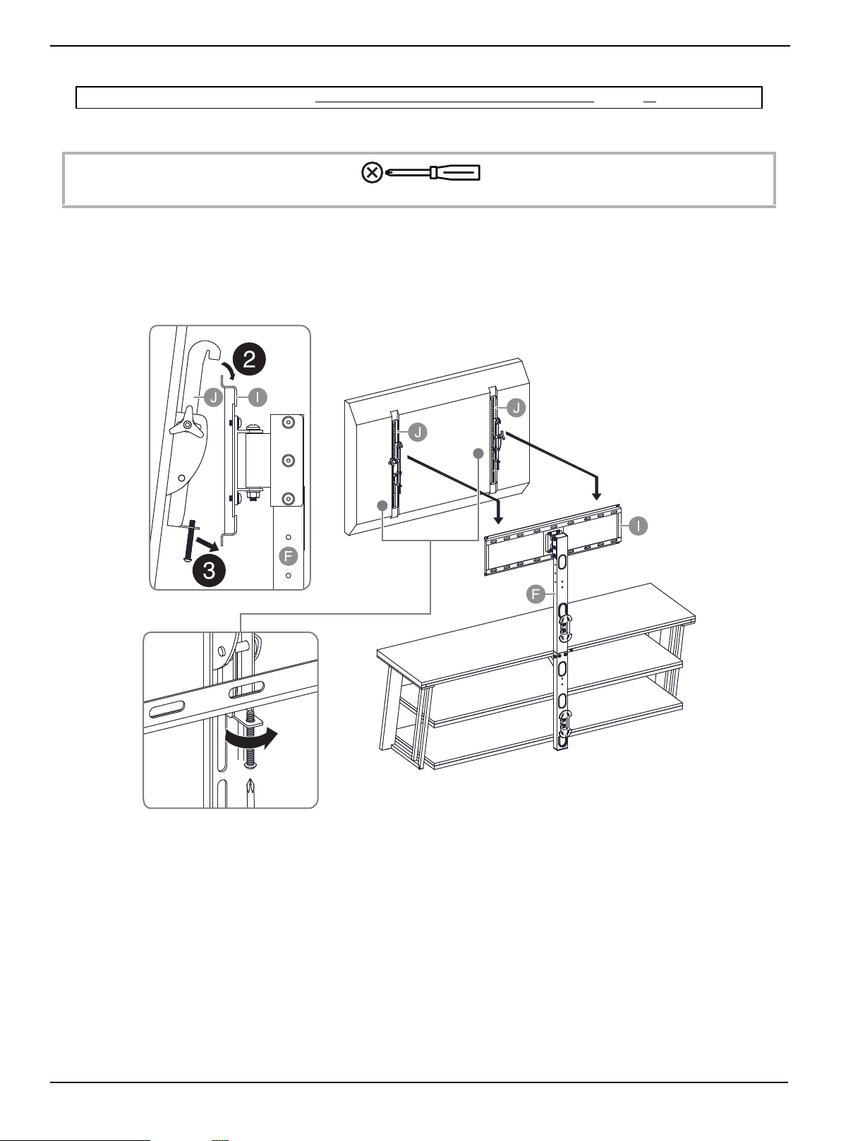
1 With the help of another adult, lift the TV up to the mounting frame (I).
2 Set the hooks on TV brackets (J) over the mounting frame (I), then lower the hooks onto the bars of the mounting
frame.
3 Center the TV, then secure it in place using a Phillips screwdriver to tighten the safety bolt on the bottom hooks.
Tighten until the safety bolt hits the underside of the mounting frame.
Note: If you are wall-mounting the TV, go to Mounting the TV using the wall-mount configuration on page 26.
Phillips screwdriver
www.insigniaproducts.com
24
STEP 8: Adjusting the tilt
You need:
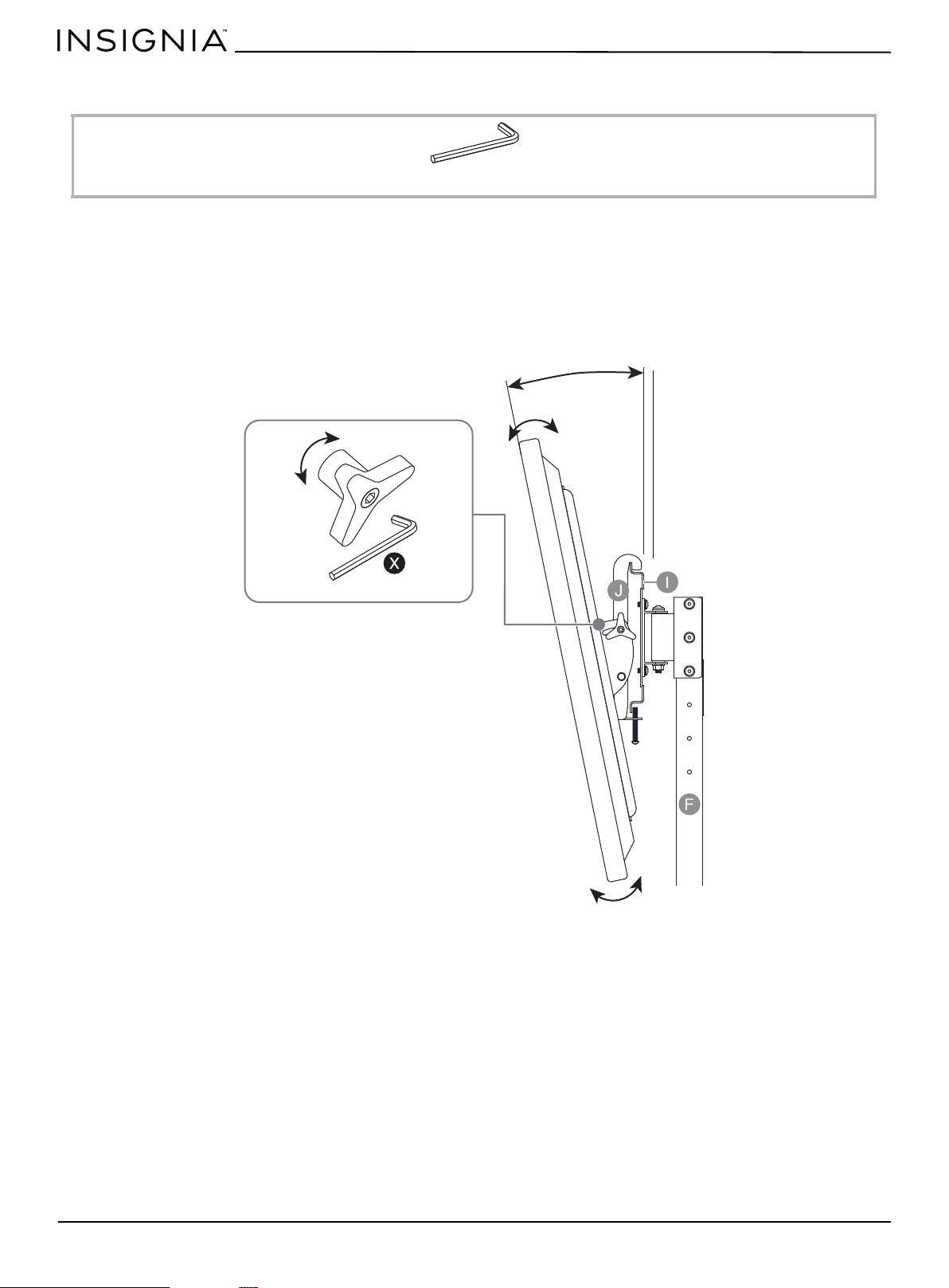
The TV brackets (J) let you make a tilt adjustment of up to 11° down and 5° up to provide optimum viewing and minimize
glare.
1 Turn the tension knobs counterclockwise to loosen the knobs on both TV brackets (J), then grasp the edge of the TV
and move it up or down to the position you want.
2 Turn the tension knob clockwise to tighten the brackets in position. Use the 4.8 mm hex wrench (X) to tighten the
tension knobs, if necessary.
X 4.8 mm Hex key (1)
-5° ~ 11°
www.insigniaproducts.com
25
3-in-1 TV Stand
STEP 9: Position your TV stand and install the tipping restraint hardware kit
You need:
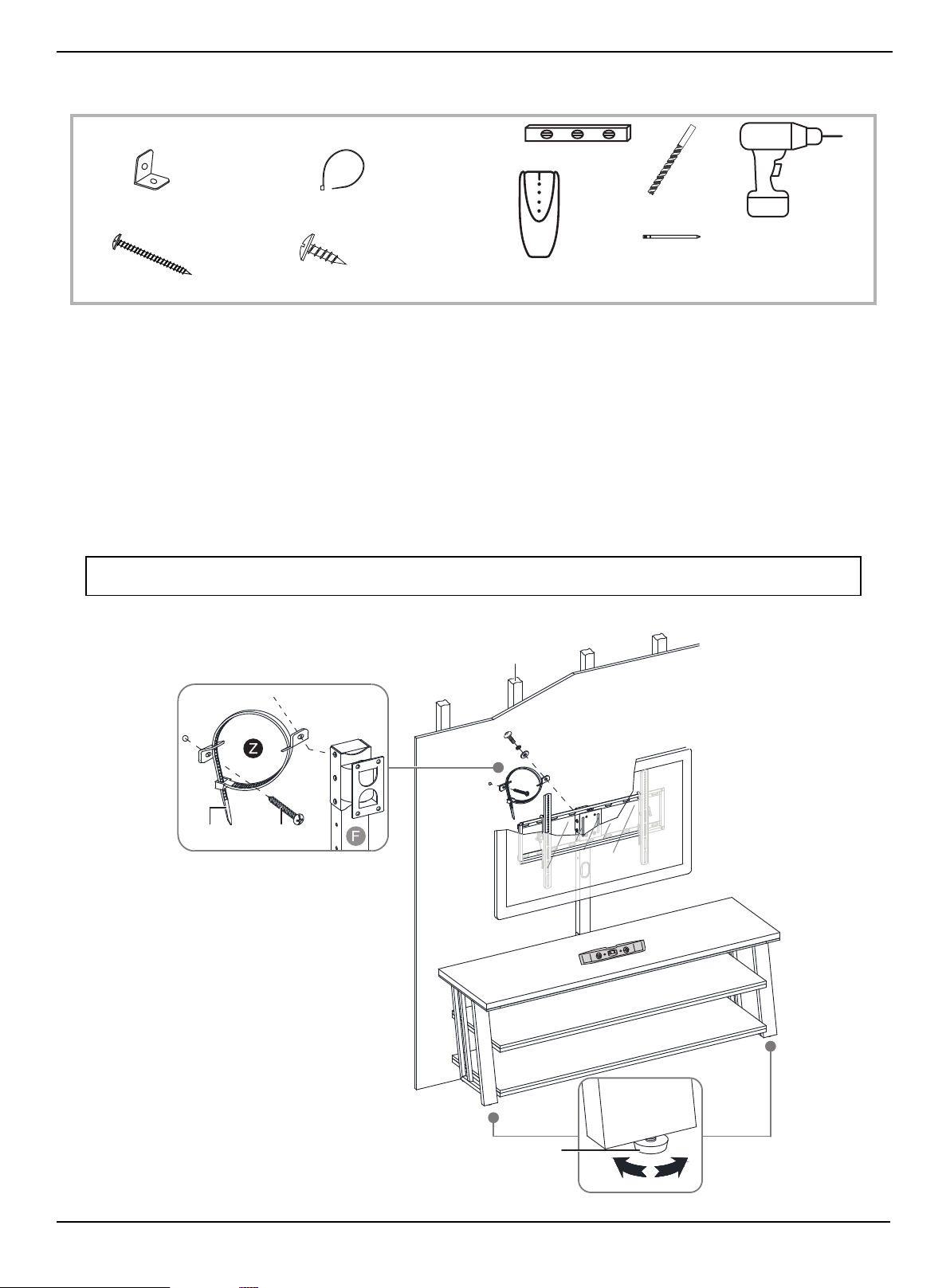
1 Position your assembled stand against a wall where you plan to use it.
2 Adjust the leveling feet to level your TV stand.
3 Align the spine (F) with a stud and mark the wall at the center point of the stud. The mark should be within 3 in.
(7.6 cm) of the bolt on the top of swivel bracket.
4 Using a 1/8" drill bit, drill a hole at the marked location and attach one metal bracket (A) using the long screw (C)
included inside the tipping restraint (Z).
5 Remove one 5/8" bolt with the washers installed on the top of swivel bracket (H).
6 Attach the other metal bracket included inside the tipping restraint (Z) to the swivel bracket (H) using the removed
bolt and washers.
7 Lace the end of the nylon strap (B) down through the mounting hole in each metal bracket. Bring both ends together
and slide the flat end through the locking end and draw it through until all slack is removed.
WARNING: The tipping restraint must be installed correctly. Failure to do this could result in your TV/stand assembly falling
forward, resulting in damage to equipment or personal injury.
Edge-to-edge stud finder
Level
Pencil
1/8" drill bit
Power drill
Z Tipping restraint hardware kit (1)
A Metal bracket (2)
C Long screw (1)
B Nylon strap (1)
D Short screw (1)
Wooden stud
Wall
Leveling feet
Long screw
Nylon strap
www.insigniaproducts.com
26
Mounting the TV using the wall-mount configuration
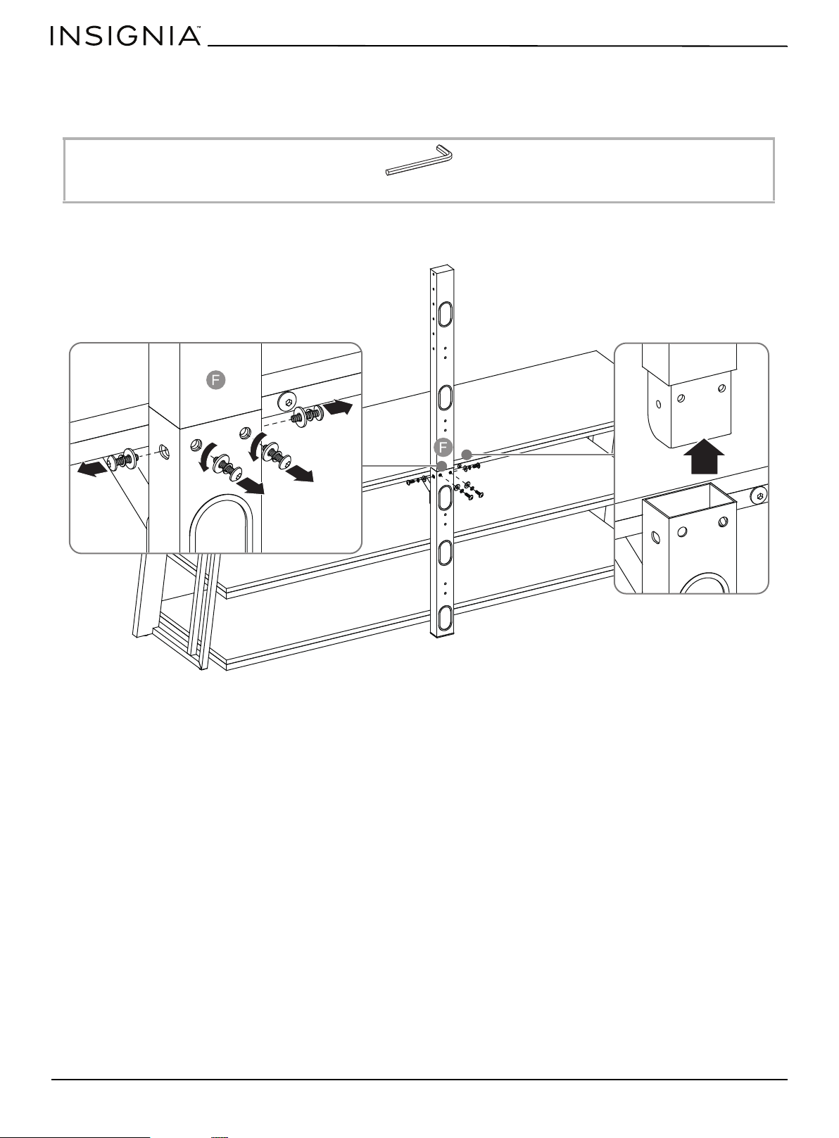
STEP 1: Remove the upper spine
You need:
• Unscrew the four bolts and the washers on the spine assembly (F), then remove the upper spine from the spine
assembly.
W 4 mm hex key (1)
www.insigniaproducts.com
27
3-in-1 TV Stand
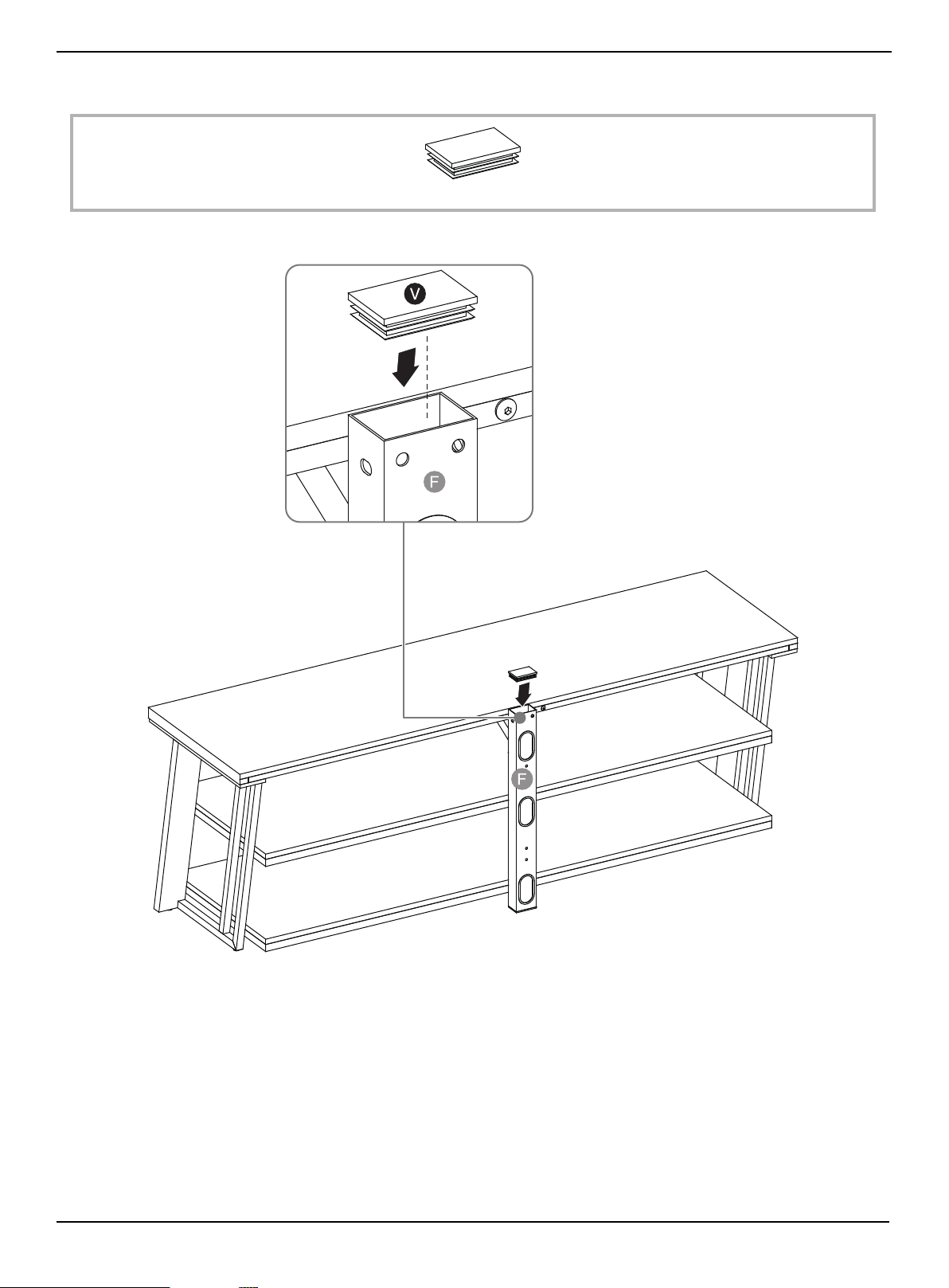
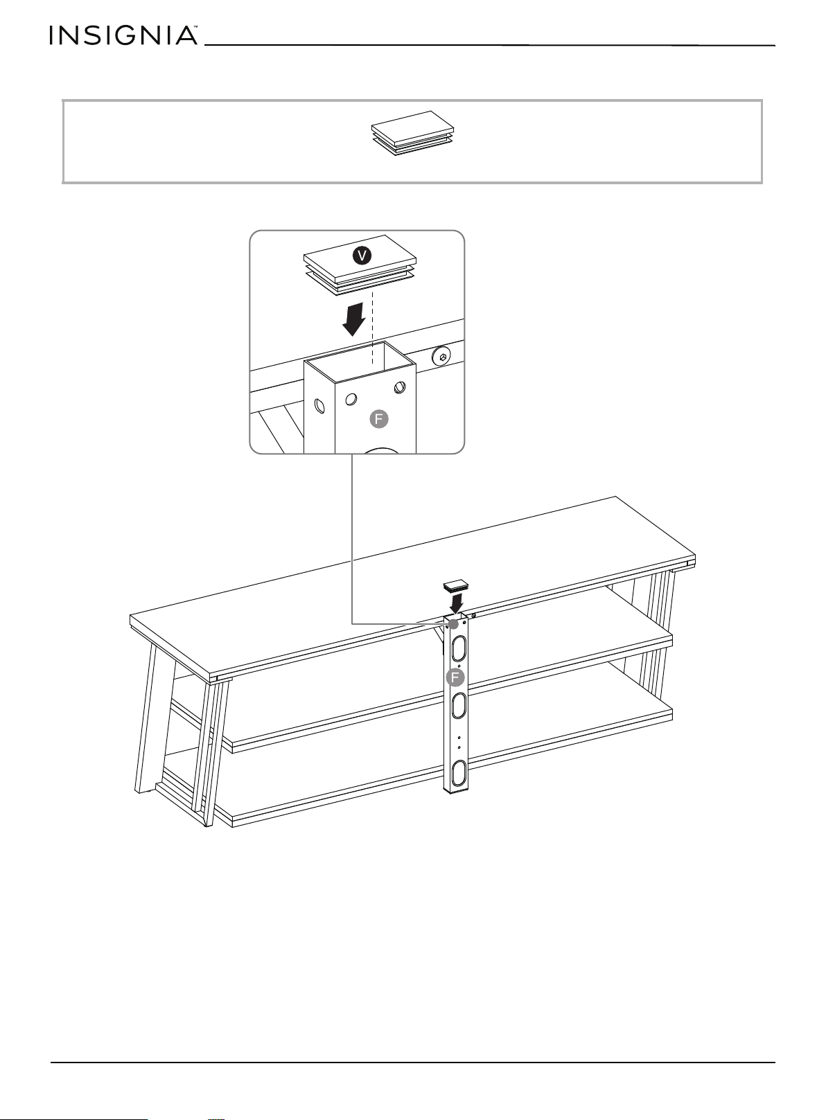
STEP 2: Insert the end cap
You need:
• Plug the plastic end cap (V) all the way onto the top of the lower spine (F).
V Plastic end cap (1)
www.insigniaproducts.com
28
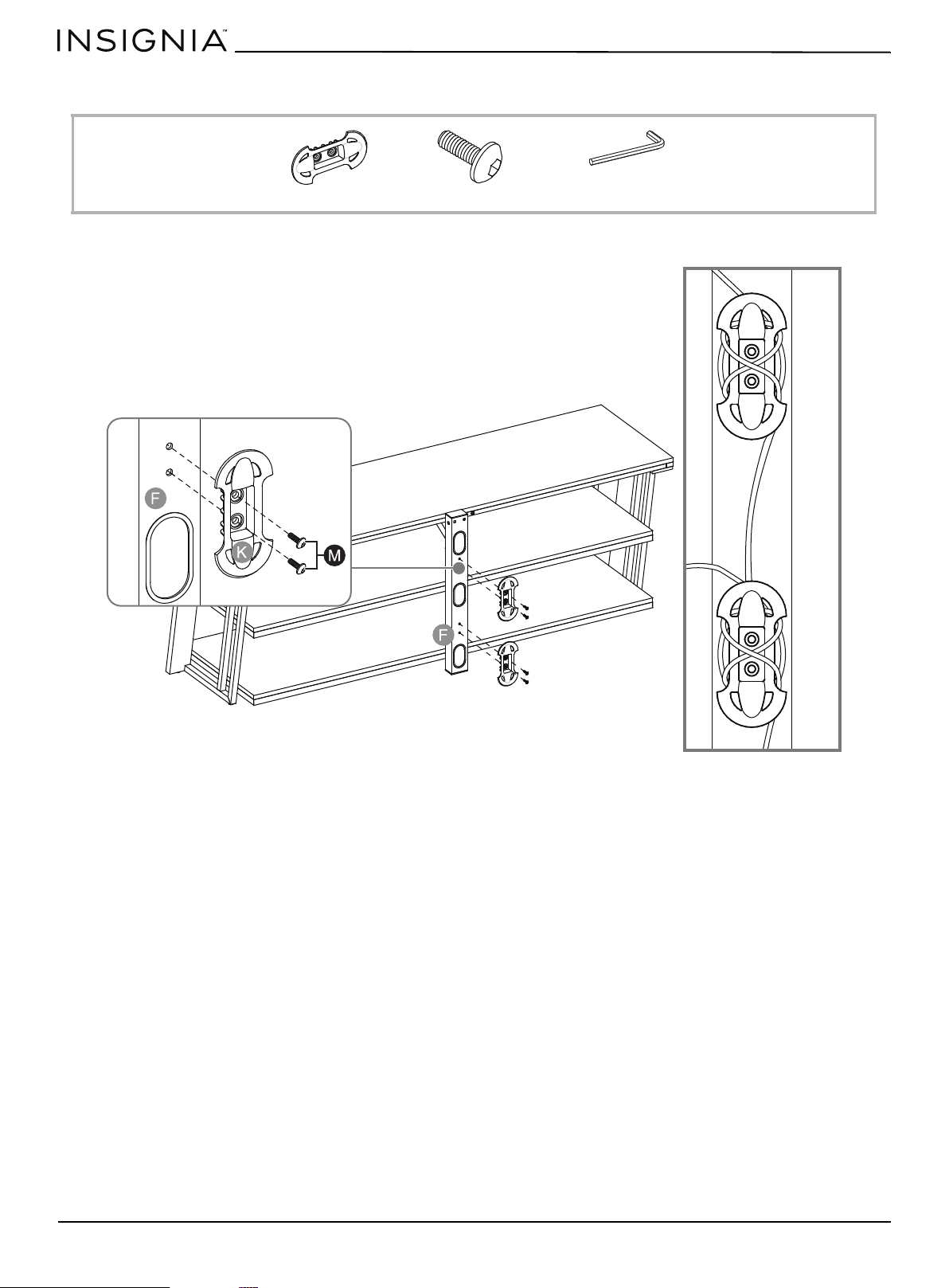
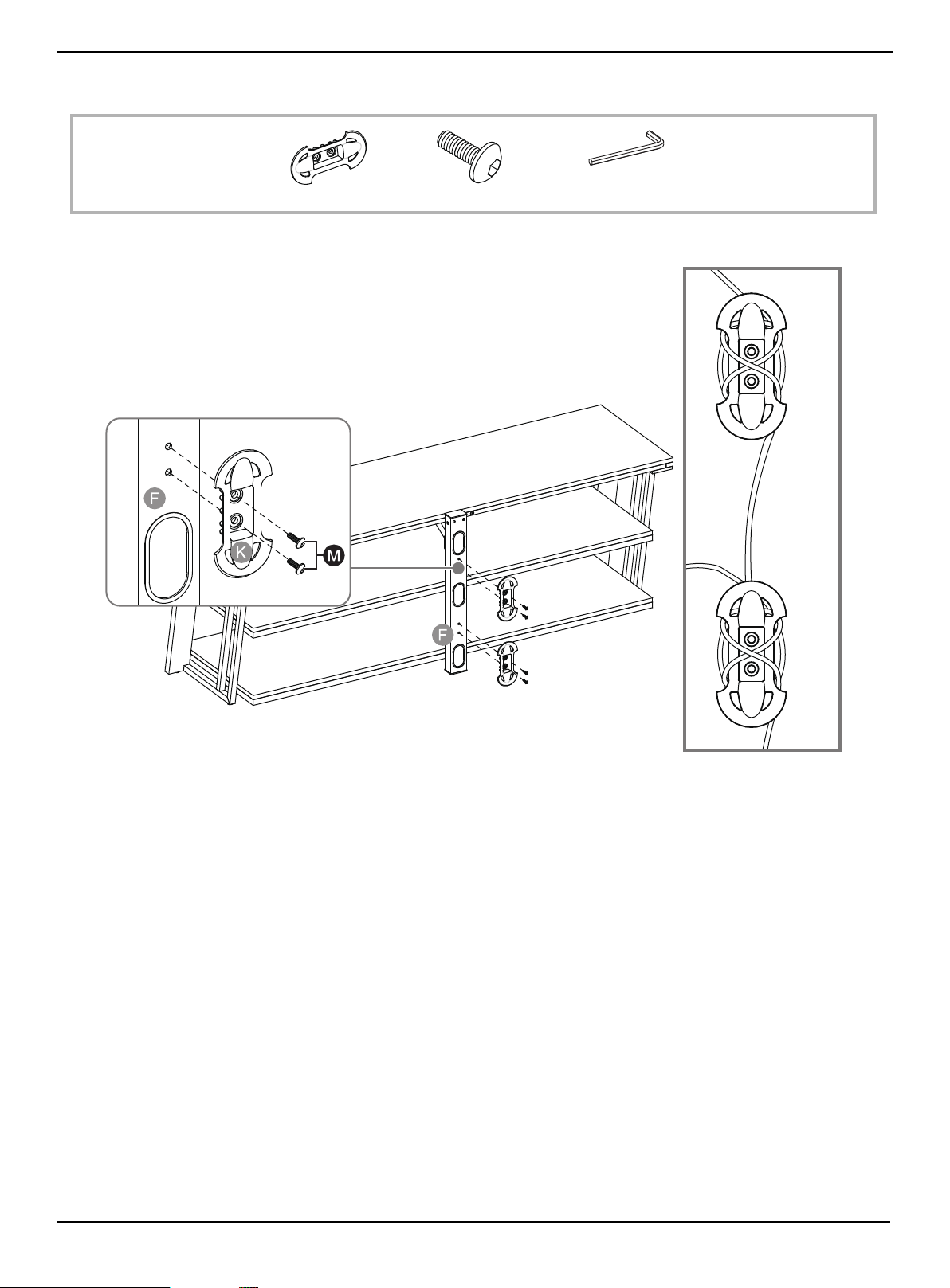
STEP 3: Attach the cable clips
You need:
• Fasten two cable clips (K) to the back of lower spine (F) using four 5/8" bolts (M).
K Cable clip (2)
M 5/8" bolt (4)
W Hex key 4 mm (1)
Cables wrapped on
cable clips
www.insigniaproducts.com
29
3-in-1 TV Stand
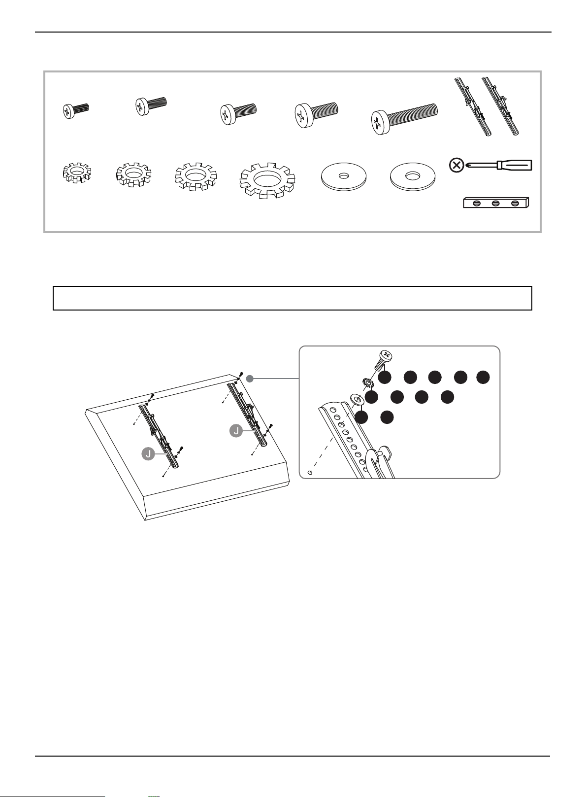
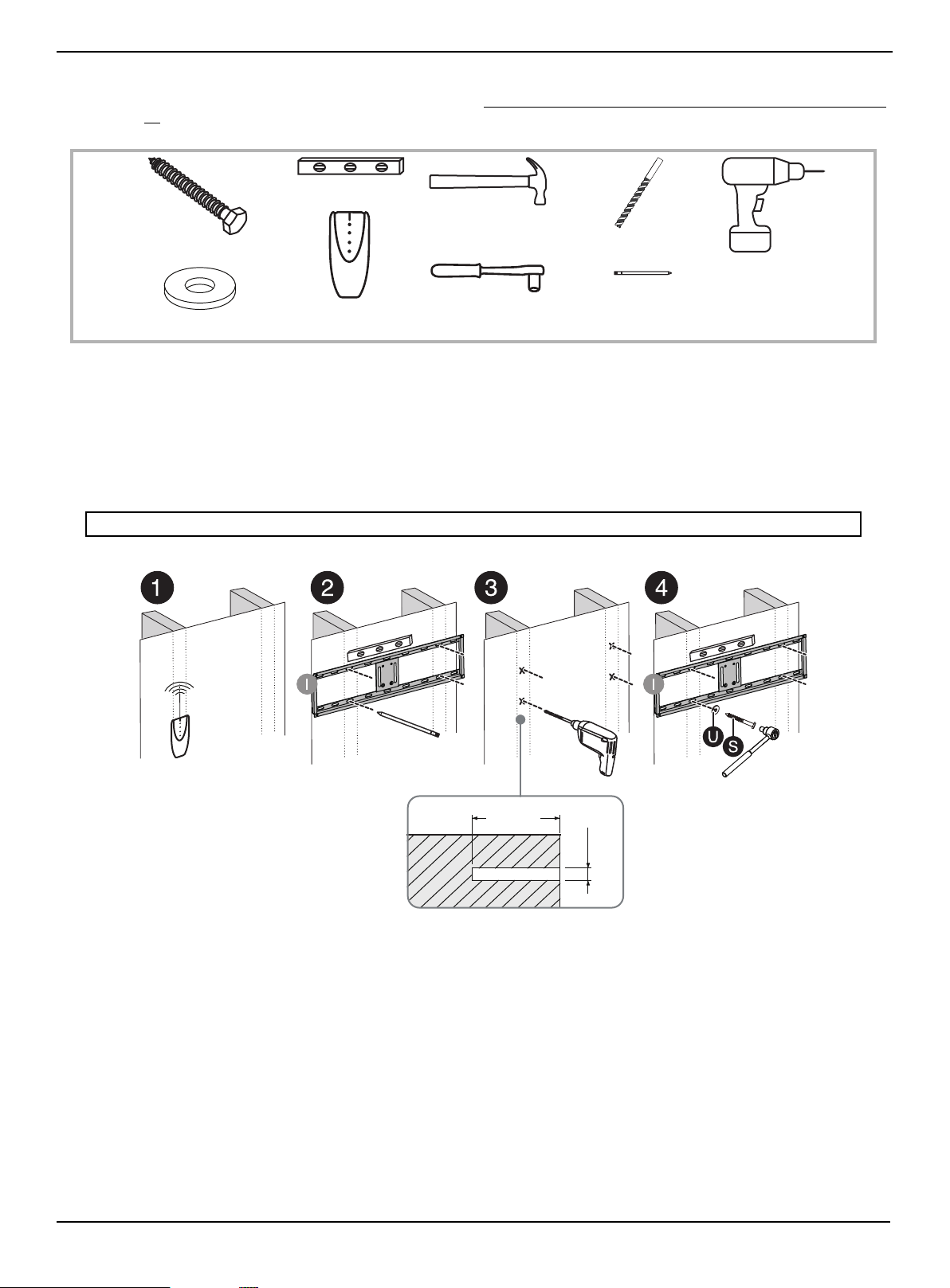
STEP 4: Option 1 - Mount the frame to a stud wall
If you are mounting the TV on a concrete or block wall, to go STEP 4: Option 2- Mount the frame to a block or concrete wall
on page 30.
You need:
1 Use a stud sensor to locate two adjacent wall studs, then position the mounting frame (I) exactly between the two
studs.
2 Use a level to make sure that the mounting frame is level, then mark the four mounting holes. Remove the mounting
frame.
3 Drill four 3/16" (4.8 mm) holes 2.5" (64 mm) deep using a drill with 3/16" a wood drill bit.
4 Align the mounting frame (I) with the pilot holes, then secure the frame to the wall with four lag bolts (S) and four
washers (U) using a socket wrench.
CAUTION: Make sure that the lag bolts are tight and secure, but do not overtighten them.
Power drill
Edge-to-edge stud finder
Hammer
Pencil
Level
Socket wrench
3/16" wood drill bit
S Lag bolt (4)
U Large flat washer (4)
2.5"
(64 mm)
.2"
(4.8 mm)
www.insigniaproducts.com
30
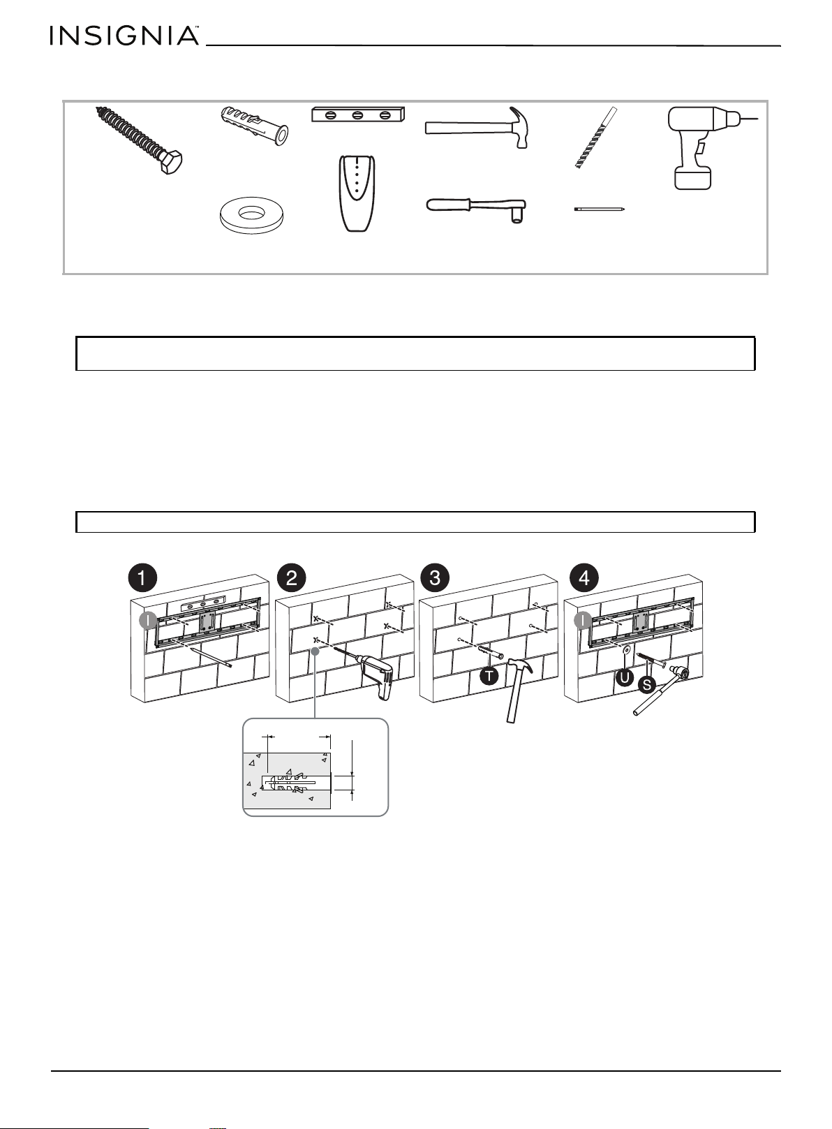
STEP 4: Option 2- Mount the frame to a block or concrete wall
You need:
1 Place the mounting frame (I) against the wall where you intend to mount the TV. Use a level to make sure that the
mounting frame is level, then mark the four mounting holes on the wall. Remove the mounting frame.
2 Drill four 7/16" (11 mm) holes through the screw marks to a depth of 2.5" (64 mm) using a drill with a 7/16" masonry
drill bit.
3 Insert a concrete anchor (T) into each of the screw holes using a hammer.
4 Align the mounting frame over the concrete anchors.
5 Place a washer (U) over one of the mounting frame screw holes, then insert a lag bolt (S) and tighten.
6 Repeat the previous step for the other three screw holes.
CAUTION: Never locate the mounting holes into the mortar between blocks. The TV may fall causing damage or
injury.
CAUTION: Make sure that the lag bolts are tight and secure, but do not overtighten them.
Power drill
Edge-to-edge
stud finder
Hammer
Pencil
Level
Socket wrench
7/16” masonry drill bit
S Lag bolt (4)
U Large flat washer (4)
T Concrete anchor (4)
2.5"
(64 mm)
(11 mm)
.4"
www.insigniaproducts.com
31
3-in-1 TV Stand
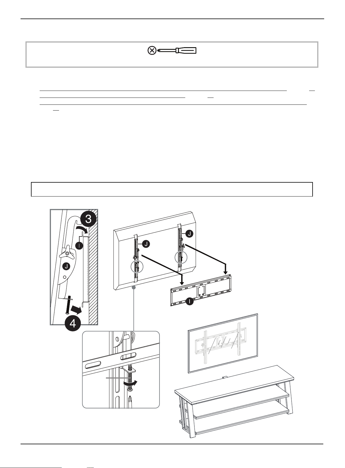
STEP 5: Attach the TV to the mounting frame on the wall
You need:
1 Depending on the type of TV that you own, attach the TV brackets (J) to the back of the TV following the steps in:
• STEP 5: Determine whether your TV has a flat back or an irregular or obstructed back or a curved screen
on page 20
• STEP 6: Option 1 - Mounting brackets on a TV with a flat back on page 21
• STEP 6: Option 2: Mounting bracket on a TV with an irregularly shaped or obstructed back or a curved screen TV
on
page 22
.
2 With the help of another adult, lift the TV up to the mounting frame (I).
3 Set the hooks on TV brackets (J) over the mounting frame, then lower the hooks onto the bars on the mounting frame.
4 Center the TV, then secure it in place using a Phillips screwdriver to tighten the safety bolt on the bottom hooks.
Tighten until the safety bolt hits the underside of the mounting frame.
5 Place your stand with the shelves under the TV.
6 Position your assembled stand against a wall where you plan to use it.
7 Adjust the leveling feet to level your TV stand.
8 Follow the instructions printed on the bag containing the tipping restraint hardware kit (Z) to attach the restraint
hardware to the wall and your stand.
WARNING: The tipping restraint must be installed correctly. Failure to do this could result in your TV/stand assembly falling
forward, resulting in damage to equipment or personal injury.
Phillips screwdriver
Note: In this step the mounting
frame has already been mounted to
the wall. This illustration shows the
TV from the back view for clarity.
Safety
bolt
www.insigniaproducts.com
32
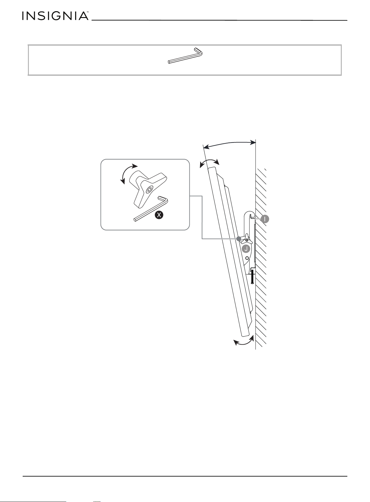
STEP 6: Adjust the tilt
You need:
The TV brackets (J) let you make a tilt adjustment of up to 11° down and 5° up to provide optimum viewing and minimize
glare.
1 Loosen the tension knobs on both TV brackets (J), then grasp the edge of the TV and move it up or down to the
position you want.
2 Turn the tension knob clockwise to secure the brackets in position. Use the 4.8 mm hex wrench (X) to tighten the
tension knobs, if necessary.
X 4.8 mm Hex key (1)
Turn clockwise to tighten.
Turn counterclockwise to loosen.
5° ~ 11°
www.insigniaproducts.com
33
3-in-1 TV Stand
Mounting the TV using the tabletop configuration
STEP 1: Remove the upper spine
You need:
• Unscrew the four bolts and the washers on the spine assembly (F), then remove the upper spine from the spine
assembly.
W 4 mm hex key (1)
www.insigniaproducts.com
34
STEP 2: Insert the end cap
You need:
• Plug the plastic end cap (V) all the way onto the top of the lower spine (F).
V Plastic end cap (1)
www.insigniaproducts.com
35
3-in-1 TV Stand
STEP 3: Attach the cable clips
You need:
• Fasten two cable clips (K) to the back of lower spine (F) using four 5/8" bolts (M).
K Cable clip (2)
M 5/8" bolt (4)
W Hex key 4 mm (1)
Cables wrapped on
cable clips
www.insigniaproducts.com
36
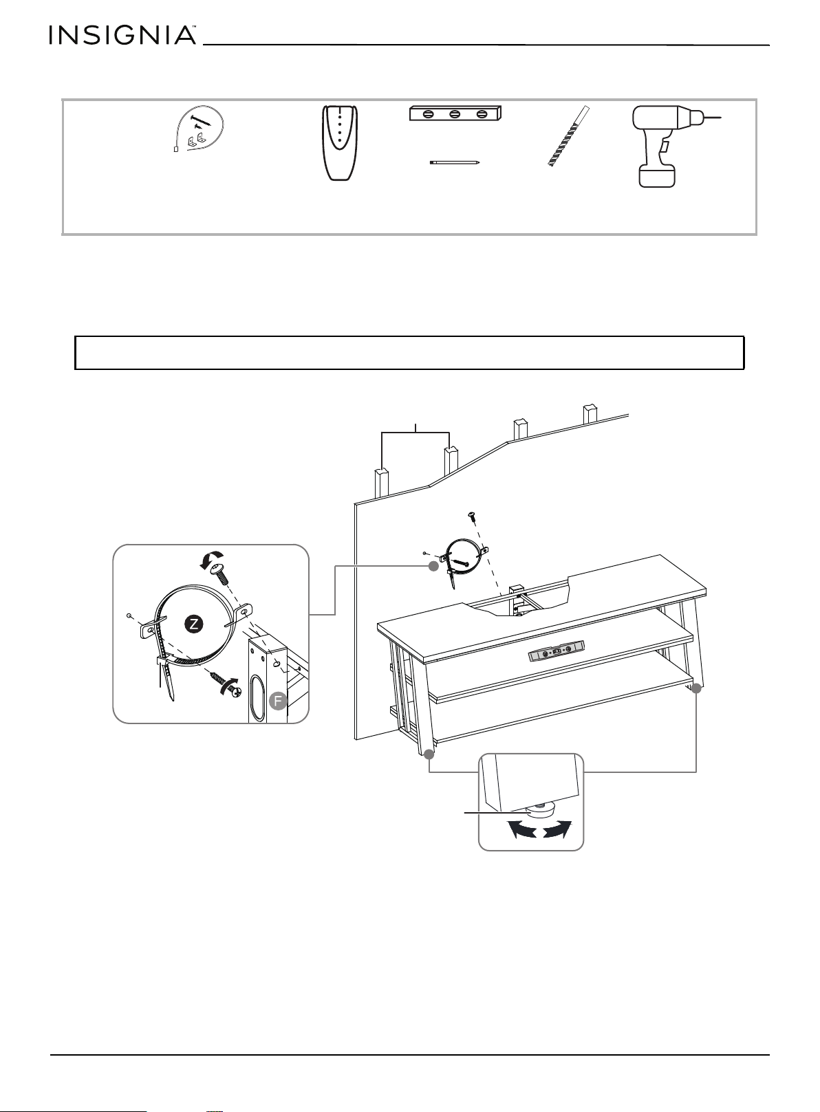
STEP 4: Position your TV stand and install the tipping restraint hardware kit
You need:
1 Position your assembled stand against a wall where you plan to use it.
2 Adjust the leveling feet to level your TV stand.
3 Follow the instructions printed on the bag containing the tipping restraint hardware kit (Z) to attach the restraint
hardware to the wall and your stand.
WARNING: The tipping restraint must be installed correctly. Failure to do this could result in your TV/stand assembly falling
forward, resulting in damage to equipment or personal injury.
Edge-to-edge stud finder
Level
Pencil
1/8" drill bit
Power drill
Z Tipping restraint
hardware kit (1)
Wooden studs
Wall
Pre-attached
bolt
Wall
Long screw
Leveling foot
Nylon strap
www.insigniaproducts.com
37
3-in-1 TV Stand
Maintaining your TV stand
Wood/Laminate
• Use your favorite type of furniture polish.
• Do not spray polish directly onto the stand. Spray onto a soft cloth, then wipe the stand.
• Always test any polish in a discrete location first, such as the back of the stand, to make sure that there is no adverse
reaction.
• Dust frequently with a soft cloth.
• Never slide objects across surfaces. Lift objects from the top surface rather than dragging them across the finish when
moving them.
• Do not expose your stand to direct sunlight, drying heat sources, or dampness.
Metal
• For everyday cleaning of chrome, brass, aluminum, and painted metal surfaces, wipe with a slightly damp, soft cotton
cloth, or vacuum to keep them looking their best.
• If soiled, wipe with clean sponge or cloth wrung out of water. Wipe dry with cloth or paper towel to avoid water spots.
• Don’t use any harsh abrasives or chemicals to clean any metal surfaces because they may damage the protective
coating.
• Metal rust if the finish is scratched or if your furniture is exposed to excessive humidity, particularly in salt water
locations.
• Most metal furniture has a protective coating to prevent rust, however rust may occur if the finish is marred or wears
away over time.
Specifications
Dimensions (H × W × D)) 22 × 65 × 20 in. (55.9 × 165.1 × 50.8 cm)
With cable clips: 22 × 65 × 21 in. (55.9 × 165.1 × 53.3 cm)
With swivel floater: 55.7 × 65 × 20 in. (146.7 × 165.1 × 50.8 cm)
Weight 3-in-1 TV stand: Net weight: 91.3 lbs. (41.5 kg)
Maximum overall weight: 200 lbs. (90.7 kg)
Maximum top shelf weight: 100 lbs. (45.3 kg)
Maximum lower shelf weight: 50 lbs. (22.6 kg)
Maximum TV weight on swivel stand: 100 lbs. (45.3 kg)
Recommended screen range 37" to 75"diagonal (32.5 - 66" width)

www.insigniaproducts.com
38
ONE-YEAR LIMITED WARRANTY
Definitions:
The Distributor* of Insignia branded products warrants to you, the original purchaser of this new Insignia-branded product (“Product”), that the
Product shall be free of defects in the original manufacturer of the material or workmanship for a period of one (1) year from the date of your purchase
of the Product (“Warranty Period”).
For this warranty to apply, your Product must be purchased in the United States or Canada from a Best Buy branded retail store or online at
www.bestbuy.com
or www.bestbuy.ca and is packaged with this warranty statement.
How long does the coverage last?
The Warranty Period lasts for 1 year (365 days) from the date you purchased the Product. Your purchase date is printed on the receipt you received
with the Product.
What does this warranty cover?
During the Warranty Period, if the original manufacture of the material or workmanship of the Product is determined to be defective by an authorized
Insignia repair center or store personnel, Insignia will (at its sole option): (1) repair the Product with new or rebuilt parts; or (2) replace the Product at
no charge with new or rebuilt comparable products or parts. Products and parts replaced under this warranty become the property of Insignia and are
not returned to you. If service of Products or parts are required after the Warranty Period expires, you must pay all labor and parts charges. This
warranty lasts as long as you own your Insignia Product during the Warranty Period. Warranty coverage terminates if you sell or otherwise transfer the
Product.
How to obtain warranty service?
If you purchased the Product at a Best Buy retail store location or from a Best Buy online website (www.bestbuy.com or www.bestbuy.ca), please take
your original receipt and the Product to any Best Buy store. Make sure that you place the Product in its original packaging or packaging that provides
the same amount of protection as the original packaging.
To obtain warranty service, in the United States call 1-888-BESTBUY or in Canada call 1-866-BESTBUY. Call agents may diagnose and correct the issue
over the phone.
Where is the warranty valid?
This warranty is valid only in the United States and Canada at Best Buy branded retail stores or websites to the original purchaser of the product in the
country where the original purchase was made.
What does the warranty not cover?
This warranty does not cover:
• Customer instruction/education
•Installation
•Set up adjustments
• Cosmetic damage
• Damage due to weather, lightning, and other acts of God, such as power surges
• Accidental damage
•Misuse
•Abuse
•Negligence
• Commercial purposes/use, including but not limited to use in a place of business or in communal areas of a multiple dwelling condominium or
apartment complex, or otherwise used in a place of other than a private home.
• Modification of any part of the Product, including the antenna
• Display panel damaged by static (non-moving) images applied for lengthy periods (burn-in).
• Damage due to incorrect operation or maintenance
• Connection to an incorrect voltage or power supply
• Attempted repair by any person not authorized by Insignia to service the Product
• Products sold “as is” or “with all faults”
• Consumables, including but not limited to batteries (i.e. AA, AAA, C, etc.)
• Products where the factory applied serial number has been altered or removed
• Loss or Theft of this product or any part of the product
• Display panels containing up to three (3) pixel failures (dots that are dark or incorrectly illuminated) grouped in an area smaller than one tenth
(1/10) of the display size or up to five (5) pixel failures throughout the display. (Pixel based displays may contain a limited number of pixels that
may not function normally.)
• Failures or Damage caused by any contact including but not limited to liquids, gels or pastes.
REPAIR REPLACEMENT AS PROVIDED UNDER THIS WARRANTY IS YOUR EXCLUSIVE REMEDY FOR BREACH OF WARRANTY. INSIGNIA SHALL NOT BE
LIABLE FOR ANY INCIDENTAL OR CONSEQUENTIAL DAMAGES FOR THE BREACH OF ANY EXPRESS OR IMPLIED WARRANTY ON THIS PRODUCT,
INCLUDING, BUT NOT LIMITED TO, LOST DATA, LOSS OF USE OF YOUR PRODUCT, LOST BUSINESS OR LOST PROFITS. INSIGNIA PRODUCTS MAKES NO
OTHER EXPRESS WARRANTIES WITH RESPECT TO THE PRODUCT, ALL EXPRESS AND IMPLIED WARRANTIES FOR THE PRODUCT, INCLUDING BUT NOT
LIMITED TO ANY IMPLIED WARRANTIES OF AND CONDITIONS OF MERCHANTABILITY AND FITNESS FOR A PARTICULAR PURPOSE, ARE LIMITED IN
DURATION TO THE WARRANTY PERIOD SET FORTH ABOVE AND NO WARRANTIES, WHETHER EXPRESS OR IMPLIED, WILL APPLY AFTER THE WARRANTY
PERIOD. SOME STATES, PROVINCES AND JURISDICTIONS DO NOT ALLOW LIMITATIONS ON HOW LONG AN IMPLIED WARRANTY LASTS, SO THE ABOVE
LIMITATION MAY NOT APPLY TO YOU. THIS WARRANTY GIVES YOU SPECIFIC LEGAL RIGHTS, AND YOU MAY ALSO HAVE OTHER RIGHTS, WHICH VARY
FROM STATE TO STATE OR PROVINCE TO PROVINCE.
Contact Insignia:
1-877-467-4289
www.insigniaproducts.com
INSIGNIA is a trademark of Best Buy and its affiliated companies.
*Distributed by Best Buy Purchasing, LLC
7601 Penn Ave South, Richfield, MN 55423 U.S.A.
©2021 Best Buy. All rights reserved.

www.insigniaproducts.com
1-877-467-4289 (U.S. and Canada) or 01-800-926-3000 (Mexico)
INSIGNIA is a trademark of Best Buy and its affiliated companies.
Distributed by Best Buy Purchasing, LLC
7601 Penn Ave South, Richfield, MN 55423 U.S.A.
©2021 Best Buy. All rights reserved.
V1 ENGLISH
21-0288