
Product Support: Eccotemp.com/help-desk Shop Online: Eccotemp.com/products Store Locater: Eccotemp.com/locater
Phone: 866-356-1992 | Email: [email protected] | Address: 315 - A Industrial RD Summerville, SC 29483
WARNING: If the information in these instructions is not followed exactly,
a re or explosion may result causing property damage, personal injury
or death.
• Do not store or use gasoline or other ammable vapors and liquids in
the vicinity of this or any other appliance.
• WHAT TO DO IF YOU SMELL GAS
• Do not try to light any appliance.
• Do not touch any electrical switch; do not use any phone in your
building.
• Immediately call your gas supplier from a neighbor’s phone.
Follow the gas supplier’s instructions.
• If you cannot reach your gas supplier, call the re department.
• Installation and service must be performed by a qualied installer
service agency or the gas supplier.
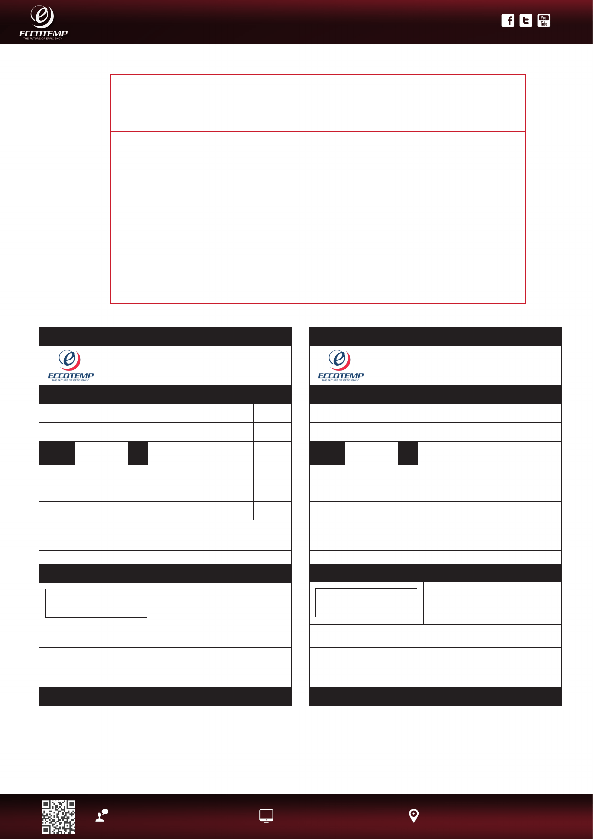
Eccotemp Systems, LLC
315-A Industrial Road
Summerville, SC 29483
866-356-1992
AUTOMATIC INSTANTANEOUS WATER HEATER
MODEL #:
i12-NG
SERIAL #:
TYPE GAS:
NATURAL GAS
ONLY Minimum Inlet Gas Pressure:
Minimum Input Rang (Btu per hour):
Maximum Input Rang (Btu per hour):
Voltage:
120 Volts
Maximum Inlet Gas Pressure:
Frequency:
60 Hz
Manifold Pressure:
Amps:
Less than 12 Amperes
Maximum Working Pressure:
Recovery
Rang:
SUITABLE FOR WATER (POTABLE) HEATING ONLY
As used in this standard, the quanty of water obtained by mulplying the
manufacturer's input rang in Btu per hour by the thermal efficiency and dividing
the product by 825 Btu per gallon. This is based on a 100°F temperature rise, and
a nominal specific heat for water of 8.25 Btu per gallon per degree F.
FOR YOUR SAFETY
Do not store or use gasoline or other
flammable vapors and liquids in the
vicinity of this or any other appliance
This appliance must be installed in accordance
with local codes or, in the absence of local
codes, the Naonal Fuel Gas Code, Natural Gas
and Propane Installaon Code
80,000
20,000
4” w.c
(1Kpa)
10.5'' w.c
(2.61Kpa)
3.05'' w.c
(0.76Kpa)
150 psi
The temperature and pressure relief valve provided by the manufacturer shall be installed at the
me of installaon of the heater in the locaon specified by the manufacturer. Local codes shall
govern installaon of relief devices. For safe operaon of the water heater, the relief valve must
not be removed or plugged.
INDOOR USE ONLY
The unit must be installed on a fire retardant area, and must be away from all combusble
materials. Clearance should be 1.75 to the le and right side of combusble materials, and
6.75 to the front.
Open on three sides and an overhead clearance of 36”
Not recommended in excess of 3,800 . above sea level.
Eccotemp Systems, LLC
315-A Industrial Road
Summerville, SC 29483
866-356-1992
AUTOMATIC INSTANTANEOUS WATER HEATER
MODEL #:
i12-LP
SERIAL #:
TYPE GAS:
LIQUID PROPANE
ONLY Minimum Inlet Gas Pressure:
Minimum Input Rang (Btu per hour):
Maximum Input Rang (Btu per hour):
Voltage:
120 Volts
Maximum Inlet Gas Pressure:
Frequency:
60 Hz
Manifold Pressure:
Amps:
Less than 12 Amperes
Maximum Working Pressure:
Recovery
Rang:
SUITABLE FOR WATER (POTABLE) HEATING ONLY
As used in this standard, the quanty of water obtained by mulplying the
manufacturer's input rang in Btu per hour by the thermal efficiency and dividing
the product by 825 Btu per gallon. This is based on a 100°F temperature rise, and
a nominal specific heat for water of 8.25 Btu per gallon per degree F.
FOR YOUR SAFETY
Do not store or use gasoline or other
flammable vapors and liquids in the
vicinity of this or any other appliance
This appliance must be installed in accordance
with local codes or, in the absence of local
codes, the Naonal Fuel Gas Code, Natural Gas
and Propane Installaon Code
80,000
20,000
9'' w.c
(2.24 Kpa)
13'' w.c
(3.23Kpa)
4.93'' w.c
(1.22Kpa)
150 psi
The temperature and pressure relief valve provided by the manufacturer shall be installed at the
me of installaon of the heater in the locaon specified by the manufacturer. Local codes shall
govern installaon of relief devices. For safe operaon of the water heater, the relief valve must
not be removed or plugged.
INDOOR USE ONLY
The unit must be installed on a fire retardant area, and must be away from all combusble
materials. Clearance should be 1.75 to the le and right side of combusble materials, and
6.75 to the front.
Open on three sides and an overhead clearance of 36”
Not recommended in excess of 3,800 . above sea level.
1
Product Support: Eccotemp.com/help-desk Shop Online: Eccotemp.com/products Store Locater: Eccotemp.com/locater
Phone: 866-356-1992 | Email: [email protected] | Address: 315 - A Industrial RD Summerville, SC 29483
PLEASE NOTE: THIS MANUAL IS SUBJECT TO CHANGE AT ANYTIME, TO ENSURE THIS MANUAL IS UP TO DATE PLEASE VISIT OUR HELPDESK AT WWW.ECCOTEMP.COM
FOR ALL OF OUR PRODUCT MANUALS.
PLEASE NOTE: THIS MODEL IS FOR INDOOR PERMANENT INSTALLATIONS ONLY.
Use & Care Manual
With Installation Instructions for the Installer
Residential Indoor Gas 80,000 BTU Max Input @ 3GPM
Tankless Water Heater
WARNING: This water heater may not be suitable for use in
manufactured (mobile) homes! Please check local code restrictions
pertaining to permanent/xed installations in manufactured homes
in your area.
The purpose of this manual is twofold: one, to provide the installer
with the basic directions and recommendations for the proper
installation and adjustment of the water heater; and two, to
the owner-operator, to explain the features, operation, safety
precautions, maintenance and troubleshooting of the water heater.
This manual also includes a parts list.
It is imperative that all persons who are expected to install,
operate or adjust this water heater read the instructions carefully
so they may understand how to perform these operations. If you
don’t understand these instructions or any terms within it, seek
professional advice.
Any questions regarding the operation, maintenance, service or
warranty of this water heater should be directed to the seller from
whom it was purchased. If additional information is required, refer to
the section on If You Need Service.
Do not destroy this manual. Please read carefully and keep in a safe
place for future reference.
Recognize this symbol as an indication of Important Safety Information!
California Proposition 65 Warning: This product contains chemicals known to the
State of California to cause cancer, birth defects or other reproductive harm.
WARNING: If the information in these instructions is not followed exactly, a re or explosion
may result causing property damage, personal injury or death.
FOR YOUR SAFETY!
Improper installation, adjustment, alteration,
service or maintenance can cause property
damage, personal injury, or death. Refer to
this manual. Installation and service must be
performed by a qualied installer, service agency
or the gas supplier.
DO NOT store or use gasoline or other ammable
vapors or liquids or other combustible materials in
the vicinity of this or any other appliance. To do so
may result in an explosion or re.
WHAT TO DO IF YOU SMELL GAS
• DO NOT try to light any appliance.
• DO NOT touch any electrical switch; do not use
any phone in your building.
• Immediately call your gas supplier from a
neighbor’s phone. Follow the gas supplier’s
instructions.
• If you cannot reach your gas supplier, call the
re department.
• DO NOT return to your home until authorized by
the gas supplier or re department.
2
Product Support: Eccotemp.com/help-desk Shop Online: Eccotemp.com/products Store Locater: Eccotemp.com/locater
Phone: 866-356-1992 | Email: [email protected] | Address: 315 - A Industrial RD Summerville, SC 29483
PLEASE NOTE: THIS MANUAL IS SUBJECT TO CHANGE AT ANYTIME, TO ENSURE THIS MANUAL IS UP TO DATE PLEASE VISIT OUR HELPDESK AT WWW.ECCOTEMP.COM
FOR ALL OF OUR PRODUCT MANUALS.
PLEASE NOTE: THIS MODEL IS FOR INDOOR PERMANENT INSTALLATIONS ONLY.
FOR YOUR RECORDS
Write the model and serial numbers here:
#_______________________________
#_______________________________
You can nd them on a label on the appliance
and/or packaging.
Staple sales slip or canceled check here.
Proof of the original purchase date is needed to
obtain service under the warranty.
READ THIS MANUAL
Inside you will nd many helpful hints on how
to use and maintain your water heater properly.
A little preventive care on your part can save
you time and money over the life of your water
heater. You’ll nd many answers to common
problems in the Troubleshooting Guide. If you
review the chart of Troubleshooting Tips rst,
you may not need to call for service.
READ THE SAFETY INFORMATION
Your safety and the safety of others are very
important. There are many important safety
messages in this manual and on your appliance.
Always read and obey all safety
messages.
This is the safety alert symbol.
Recognize this symbol as an indication
of Important Safety Information! This
symbol alerts you to potential hazards
that can kill or hurt you and others.
All safety messages will follow the safety
alert symbol and either the word “DANGER”,
“WARNING”, “CAUTION” or “NOTICE”.
These words mean:
DANGER - An imminently hazardous situation that will
result in death or serious injury.
WARNING - A potentially hazardous situation
that could result in death or serious injury and/or
damage to property.
CAUTION - A potentially hazardous situation that
may result in minor or moderate injury.
NOTICE: Attention is called to observe a specied
procedure or maintain a specic condition.
Safety Information
Safety Precautions .................6
LP Gas Models .......................5
Installation Instructions
Location ..............................7-9
Water Connections ......... 10-11
Relief Valve.............................11
Gas Supply..............................12
Leak Testing............................12
High Altitude ......................... 12
Typical Installation ..........13-14
Venting ............................ 15-19
Electrical Connection ............20
Pipe Insulation .......................21
Installation Checklist ............22
Operating Instructions
Start Instructions ........... 23-24
Water Temperature ..............25
Temperature Memory.......... 25
Care and Cleaning
Maintenance ........................ 26
Housekeeping ..................26-27
Vent Inspection..................... 27
Extended Shut-Down ...........27
No Anti-freezing....................27
Draining .......................... 27-28
Troubleshooting Tips
Before You Call .................... 29
Error Code Guide ..................30
Customer Service
Parts List................................31
3
Product Support: Eccotemp.com/help-desk Shop Online: Eccotemp.com/products Store Locater: Eccotemp.com/locater
Phone: 866-356-1992 | Email: [email protected] | Address: 315 - A Industrial RD Summerville, SC 29483
PLEASE NOTE: THIS MANUAL IS SUBJECT TO CHANGE AT ANYTIME, TO ENSURE THIS MANUAL IS UP TO DATE PLEASE VISIT OUR HELPDESK AT WWW.ECCOTEMP.COM
FOR ALL OF OUR PRODUCT MANUALS.
PLEASE NOTE: THIS MODEL IS FOR INDOOR PERMANENT INSTALLATIONS ONLY.
IMPORTANT SAFETY INFORMATION READ ALL
INSTRUCTIONS BEFORE USING
Be sure to read and understand the entire Use and Care Manual before attempting to install or
operate this water heater. It may save you time and money. Pay particular attention to the Safety
Instructions. Failure to follow these warnings could result in serious bodily injury or death. Should
you have problems understanding the instructions in this manual, or have any questions, STOP, and
get help from a qualied service technician, or the local gas utility.
DANGER!
PROPERLY INSTALL WATER HEATER
Failure to properly install the water heater outdoors as outlined in the Installation
Instructions in this manual can result in unsafe operation of the water heater. To
avoid the risk of re, explosion, or asphyxiation from carbon monoxide, never
operate this water heater unless it is installed properly and has an adequate
air supply for proper operation. Be sure to inspect the ue terminal for proper
installation at initial start-up; and at least annually thereafter. Refer to the Care
and Cleaning section of this manual for more information regarding ue terminal
inspection.
WARNING!
Gasoline, as well as other ammable materials and liquids (adhesives, solvents,
paint thinners etc.) and the vapors they produce are extremely dangerous. DO NOT
handle, use or store gasoline or other ammable or combustible materials any
where near or in the vicinity of a water heater or any other appliance. Be sure to
read and follow the labels on the water heater, as well as the warnings printed in
this manual. Failure to do so can result in property damage, bodily injury or death.
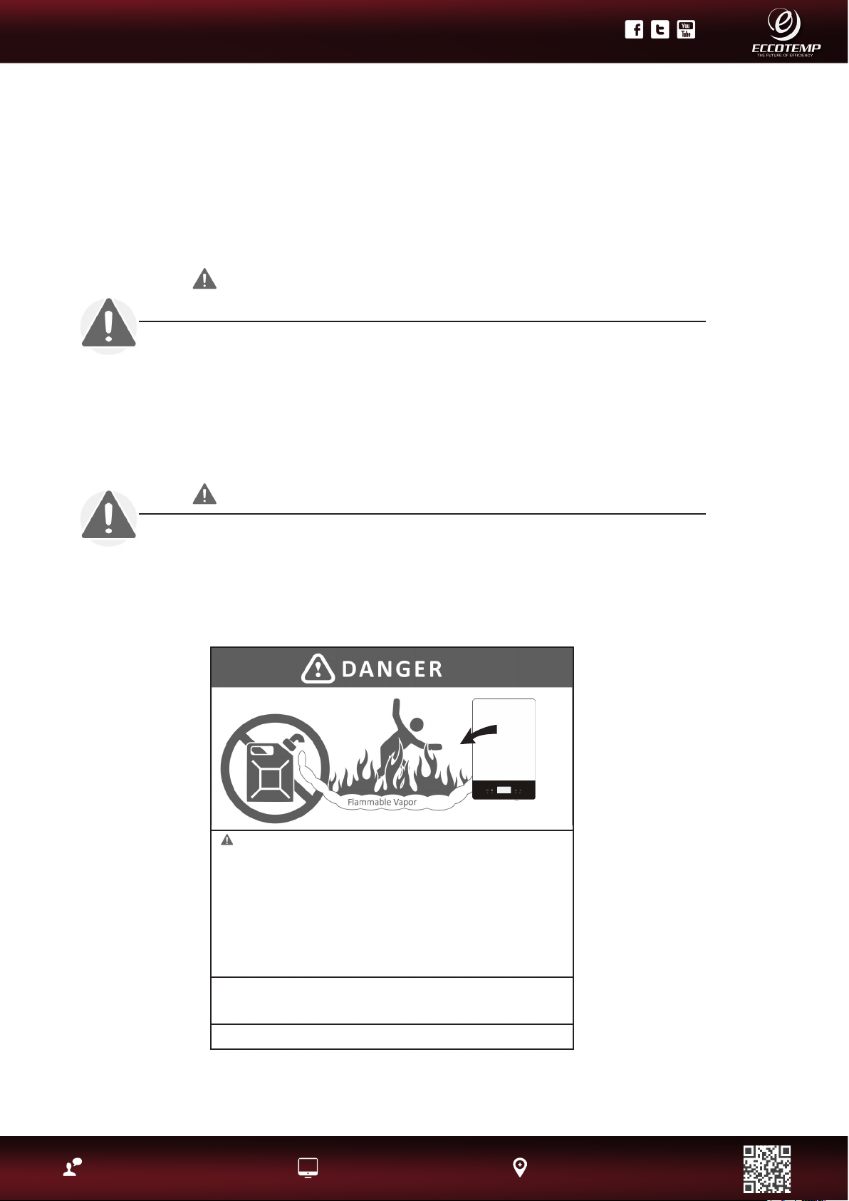
Vapors from ammable liquids
will explode and catch re causing
death or severe burns.
Do not use or store ammable products
such as gasoline, solvents or adhesives
in the same room or area near the water
heater.
Keep ammable products :
1. Far away from heater
2. In approved containers
3. Tightly closed
4. Out of children ‘s reach
Water heater has a main burner ame.
The main burner ame
1. Can come on at any time and
2. Will ignite ammable vapors.
Vapors:
1. Cannot be seen
2. Are heavier than air
3. Go a long way on the oor
4. Can be carried from other rooms to the
main burner ame by air currents.
Installation:
Do not Install water heater where ammable products will be stored or used unless the
main burner ame Is at least 18” above the oor. This will reduce, but not eliminate, the
risk of vapors being ignited by the main burner ame.
Read and follow water heater warnings and Instructions. If owners manual is missing,
contact the retailer or manufacturer.
4
Product Support: Eccotemp.com/help-desk Shop Online: Eccotemp.com/products Store Locater: Eccotemp.com/locater
Phone: 866-356-1992 | Email: [email protected] | Address: 315 - A Industrial RD Summerville, SC 29483
PLEASE NOTE: THIS MANUAL IS SUBJECT TO CHANGE AT ANYTIME, TO ENSURE THIS MANUAL IS UP TO DATE PLEASE VISIT OUR HELPDESK AT WWW.ECCOTEMP.COM
FOR ALL OF OUR PRODUCT MANUALS.
PLEASE NOTE: THIS MODEL IS FOR INDOOR PERMANENT INSTALLATIONS ONLY.
IMPORTANT SAFETY INFORMATION
READ ALL INSTRUCTIONS BEFORE USING
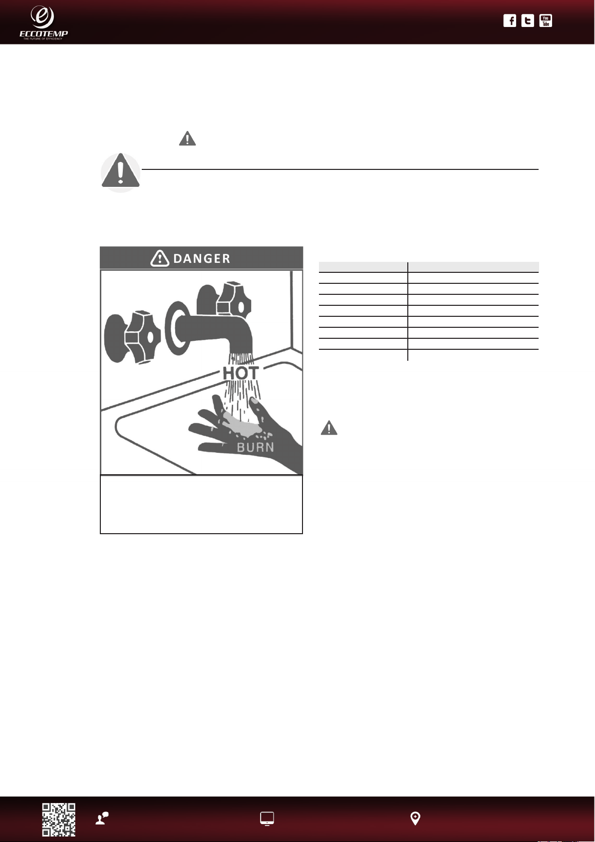
DANGER!
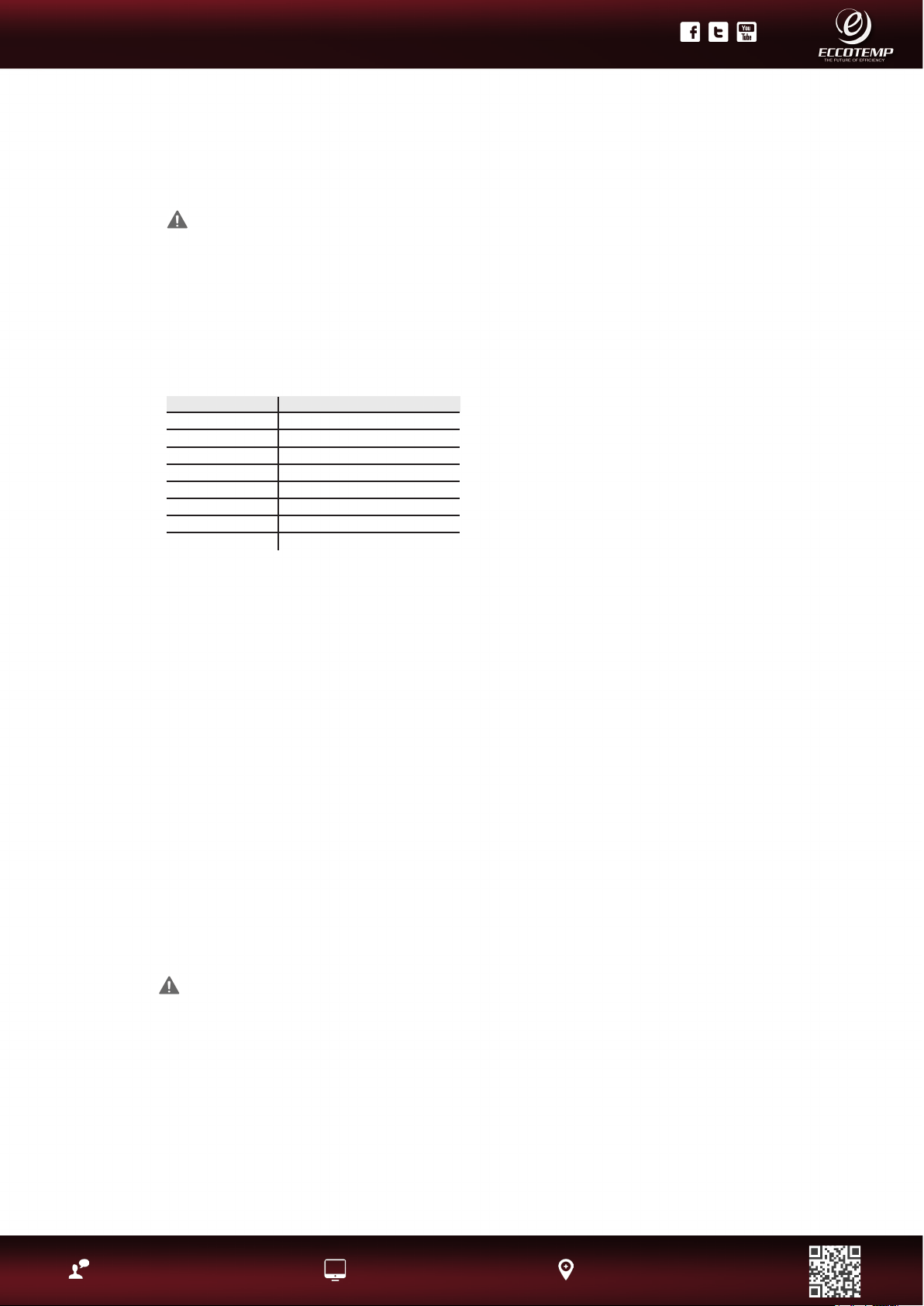
WATER TEMPERATURE SETTING
Safety and energy conservation are factors to be considered when selecting
the water temperature setting. Water temperatures above 125°F can cause
severe burns or death from scalding. The thermostat is adjusted to its lowest
temperature position when shipped from the factory. Be sure to read and follow
the warnings outlined on the label pictured below.
The chart shown above may be used as a guide
in determining the proper water temperature for
your home
DANGER: Households with small children,
disabled, or elderly persons may require a 120°F.
or lower temperature setting to prevent contact
with”HOT” water.
Maximum water temperature occurs while
burner is on. To nd water temperature being
delivered, turn on a hot water faucet and place a
thermometer in the water stream and read the
thermometer.
The temperature of the water at the outlet of
the water heater can be regulated by setting
the temperature on front side of water heater.
The water heater was set at 110°F before it was
shipped from the factory.
NOTICE: When this water heater is supplying
general purpose hot water requirements for
use by individuals, a thermostatically controlled
mixing valve for reducing point of use water
temperature is recommended to reduce the risk
of scald injury. Contact a licensed plumber or the
local plumbing authority for further information.
The factory recommended operating
temperatures are between 90°F and 140°F.
Water Temperature
120°F
125°F
130°F
135°F
140°F
145°F
150°F
155°F
Time To Produce a Serious Burn
More than 5 minutes
1 1/2to 2 minutes
About 30 seconds
About 10 seconds
Less than 5 seconds
Less than 3 seconds
About 1 1/2 seconds
About 1 second
Time/Temperature Relationship in Scalds
Table courtesy of Shriners Burn Institute
Water temperature over 125°F can cause severe burns
instantly or death from scalds. Children, disabled and elderly
are at highest risk of being scalded. See instruction manual
before setting temperature at water heater. Feel water
before bathing or showering. Temperature limiting valves are
available, see manual.
5
Product Support: Eccotemp.com/help-desk Shop Online: Eccotemp.com/products Store Locater: Eccotemp.com/locater
Phone: 866-356-1992 | Email: [email protected] | Address: 315 - A Industrial RD Summerville, SC 29483
PLEASE NOTE: THIS MANUAL IS SUBJECT TO CHANGE AT ANYTIME, TO ENSURE THIS MANUAL IS UP TO DATE PLEASE VISIT OUR HELPDESK AT WWW.ECCOTEMP.COM
FOR ALL OF OUR PRODUCT MANUALS.
PLEASE NOTE: THIS MODEL IS FOR INDOOR PERMANENT INSTALLATIONS ONLY.
DANGER!
NATURAL GAS AND LIQUEFIED PETROLEUM MODELS
Both LP and natural gas have an odorant added to aid in detecting a gas leak.
Some people may not physically be able to smell or recognize this odorant. If you
are unsure or unfamiliar with the smell of LP or natural gas, ask the gas supplier.
Other conditions, such as “odorant fade”, which causes the odorant to diminish in
intensity, can also hide or camouage a gas leak. Always check with commercial
leak detector or soapy water.
• Gas detectors are recommended in LP and natural gas applications and
their installation should be in accordance with the detector manufacturer’s
recommendations and/or local laws, rules, regulations or customs.
• Water heaters utilizing LP gas are different from natural gas models. A natural
gas water heater will not function safely on LP gas and vice versa.
• No attempt should ever be made to convert the water heater from natural gas
to LP gas. To avoid possible equipment damage, personal injury or re, do not
connect the water heater to a fuel type not in accordance with the unit data
plate; propane for propane units and natural gas for natural gas units. These
units are not certied for any other fuel type.
• LP appliances should not be installed· below grade (for example, in a basement)
if such installation is prohibited by federal, state and/or local laws, rules,
regulations or customs.
• Propane or LP gas must be used with great caution. It is heavier than air and will
collect rst in lower areas making it hard to detect at nose level.
• Before attempting to light the water heater, make sure to look and smell for gas
leaks. Use a soapy solution to check all gas ttings and connections. Bubbling at
a connection indicates a leak that must be corrected. When smelling to detect a
gas leak, be sure to sniff near the oor also.
• It is recommended that more than one method, such as soapy solution, gas
detectors, etc., be used to detect leaks in gas applications.
Notice: If a gas leak is present or suspected:
• DO NOT attempt to nd the cause yourself.
• DO NOT try to light any appliance.
• DO NOT touch any electrical switch.
• DO NOT use any phone in your building.
• Leave the house immediately and make sure your family and pets leave also.
• Leave the doors open for ventilation and contact the gas supplier, a qualied
service agency or the re department.
• Stay away from the house (or building) until the service call has been made,
the leak is corrected and a qualied agency has determined the area to be safe.
WARNING - Not intended or to be used for fuel types not listed on your tankless
water heater rating plate.
6
Product Support: Eccotemp.com/help-desk Shop Online: Eccotemp.com/products Store Locater: Eccotemp.com/locater
Phone: 866-356-1992 | Email: [email protected] | Address: 315 - A Industrial RD Summerville, SC 29483
PLEASE NOTE: THIS MANUAL IS SUBJECT TO CHANGE AT ANYTIME, TO ENSURE THIS MANUAL IS UP TO DATE PLEASE VISIT OUR HELPDESK AT WWW.ECCOTEMP.COM
FOR ALL OF OUR PRODUCT MANUALS.
PLEASE NOTE: THIS MODEL IS FOR INDOOR PERMANENT INSTALLATIONS ONLY.
IMPORTANT SAFETY INFORMATION READ ALL
INSTRUCTIONS BEFORE USING
FOR INSTALLATIONS IN THE STATE OF CALIFORNIA
California Law requires that residential water heaters must be braced, anchored
or strapped to resist falling or horizontal displacement due to earthquake
motions. For residential water heaters up to 52 gallon capacity, a brochure with
generic earthquake bracing instructions can be obtained from: Ofce of the State
Architect, 400 P Street, Sacramento, CA 95814 or you may call 916-445-8100 or
ask a water heater dealer.
However, applicable local codes shall govern installation. For residential water
heaters of a capacity greater than 52 gallons or tankless style, consult the local
building jurisdiction code for acceptable bracing procedures.
SAFETY PRECAUTIONS
Have the installer show you the location of the gas shut-off valve and how to shut
it off if necessary. Turn off the manual shut-off valve if the water heater has been
subjected to overheating, re, ood, physical damage or if the gas supply fails to
shut off.
• Read this manual entirely before installing or operating the water heater.
• Use this appliance only for its intended purpose as described in this Use and
Care Manual.
• Be sure your appliance is properly installed in accordance with local codes and
the provided installation instructions.
• Part of your water heater unless it is specically recommended in this manual.
• All other servicing should be referred to a qualied technician.
READ AND FOLLOW THIS SAFETY INFORMATION CAREFULLY
SAVE THESE INSTRUCTIONS
WARNING!
For your safety, the information in this manual must be followed to minimize the
risk of re or explosion, electric shock, or to prevent property damage, personal
injury, or loss of life.
7
Product Support: Eccotemp.com/help-desk Shop Online: Eccotemp.com/products Store Locater: Eccotemp.com/locater
Phone: 866-356-1992 | Email: [email protected] | Address: 315 - A Industrial RD Summerville, SC 29483
PLEASE NOTE: THIS MANUAL IS SUBJECT TO CHANGE AT ANYTIME, TO ENSURE THIS MANUAL IS UP TO DATE PLEASE VISIT OUR HELPDESK AT WWW.ECCOTEMP.COM
FOR ALL OF OUR PRODUCT MANUALS.
PLEASE NOTE: THIS MODEL IS FOR INDOOR PERMANENT INSTALLATIONS ONLY.
Indoor Location
• Installation distances may vary by local code. It is the installer’s responsibility to verify
installation requirements.
• Make sure before installation that the gas type you will use is the same type on the data plate.
• The water heater unit should be installed by professionals. Improper installation may cause
failure or dangerous conditions such as gas leaking or explosion.
• Water Heater cannot be installed in an UN-VENTED bathroom, bedroom, basement, living room,
closet, outdoor, stairway or an exit area. If installed in an exit area, it must be at least 16.5 ft. or
more away from the exit.
• Vent pipe should extend from the wall at least 2”. The terminal must be at least 1.64 ft. away
from obstruction, and must be well vented.
• Vent pipe should slope 3° downward, to avoid condensing water and protect from rain entering.
• Vent pipe should avoid direct, strong wind because the downdraft will cause malfunction.
• The unit should be installed far from any blockage, and with plenty of enough space for
installation and maintenance. Adequate clearances for servicing must be provided.
• The unit should not be installed in the same room with a gas stove .
• When determining the oor clearance, a clearance of 6 inches must be maintained between the
vent pipe and combustible material. A side wall clearance of 6 inches and a top clearance of 12
inches must be maintained.
• A maximum of 32 feet of vent pipe may be used provided there is only one 90° elbow in the
system. If additional elbows are required: two elbows can be used with 27 feet, and three
elbows can be used with 22 feet of vent pipe.
• A 90° elbow is equivalent to 5 feet of straight pipe. A 45° elbow is equivalent to 2 feet 6 inches
of straight pipe .
• The vent pipe should be installed with a ame retardant wall thimble. Owner must refer to vent
manufacturer’s instructions and specications.
• The power socket connecting the water heater should be grounded properly with a GFCI circuit
protector.
• The water heater should not be located in an area where leakage of the heat exchanger or
connections will result in damage to the area adjacent to it or to lower oors of the structure.
When such areas cannot be avoided it is recommended that a suitable catch pan, adequately
drained, must be installed under the water heater. The pan must not restrict combustion
airow.
• The water heater should be installed as close as practical to the vent termination to minimize
vent length and the number of elbows required for venting.
• A gas red water heater or any other appliance should not be installed in a space where liquids
which give off ammable vapors are to be used or stored. Such liquids include gasoline, LP gas
(butane or propane), paint or adhesives and their thinners, solvents or removers.
Installing the water heater
8
Product Support: Eccotemp.com/help-desk Shop Online: Eccotemp.com/products Store Locater: Eccotemp.com/locater
Phone: 866-356-1992 | Email: [email protected] | Address: 315 - A Industrial RD Summerville, SC 29483
PLEASE NOTE: THIS MANUAL IS SUBJECT TO CHANGE AT ANYTIME, TO ENSURE THIS MANUAL IS UP TO DATE PLEASE VISIT OUR HELPDESK AT WWW.ECCOTEMP.COM
FOR ALL OF OUR PRODUCT MANUALS.
PLEASE NOTE: THIS MODEL IS FOR INDOOR PERMANENT INSTALLATIONS ONLY.
• The unit should be installed far from heat sources, ammable and dangerous materials.
Because of natural air movement in a room or other enclosed space, ammable vapors can
be carried some distance from where their liquids are being used or stored. The open ame of
the water heater’s main burner can ignite these vapors causing an explosion or re which may
result in severe burns, death or property damage.
• Raising the water heater will reduce, BUT NOT eliminate the possibility of lighting the vapor of
any ammable liquids which may be improperly stored or accidentally spilled .
• If the water heater is installed in a garage, it should be installed so that the direct ignition
system and main burner are no less than 18 inches above the garage oor.
• Hot and cold water lines should be insulated to conserve water and energy.
• The water heater must be located so it is not subject to physical damage, for example, by
moving vehicles, area ooding, etc.
• The water heater should be installed with the proper venting materials and termination suitable
for Category III venting. Failure to install and properly vent the water heater to the outdoors as
outlined in the Venting Section of this manual can result in unsafe operation. Owner must refer
to vent manufacturer’s instructions and specications.
• For other than a direct vent appliance, the appliance must be located as close as practicable to a
chimney or gas vent.
• DO NOT install water heater where subject to vibrations or on the road use.
• DO NOT install the water heater in Recreational Vehicles, Mobile Homes, Boats and other
Watercraft.
• DO NOT install the water heater near vents for heating or cooling. A minimum of 4 feet should
be maintained.
• If the clearances stated on the Instruction/Warning Label, located on the front panel of the
heater differ, install the water heater according to the clearances stated on the label.
Installing the water heater continued....
WARNING: Combustible construction refers to adjacent walls and ceilings and should not be
confused with combustible or ammable products and materials. Combustible and/or ammable
products and materials should never be stored in the vicinity of this or any gas appliance.
9
Product Support: Eccotemp.com/help-desk Shop Online: Eccotemp.com/products Store Locater: Eccotemp.com/locater
Phone: 866-356-1992 | Email: [email protected] | Address: 315 - A Industrial RD Summerville, SC 29483
PLEASE NOTE: THIS MANUAL IS SUBJECT TO CHANGE AT ANYTIME, TO ENSURE THIS MANUAL IS UP TO DATE PLEASE VISIT OUR HELPDESK AT WWW.ECCOTEMP.COM
FOR ALL OF OUR PRODUCT MANUALS.
PLEASE NOTE: THIS MODEL IS FOR INDOOR PERMANENT INSTALLATIONS ONLY.
Proper operation of the water heater requires air for combustion and ventilation. Provisions for
combustion and ventilation air must comply with referenced codes and standards.
Combustion and Ventilation Air
Installing the water heater continued....
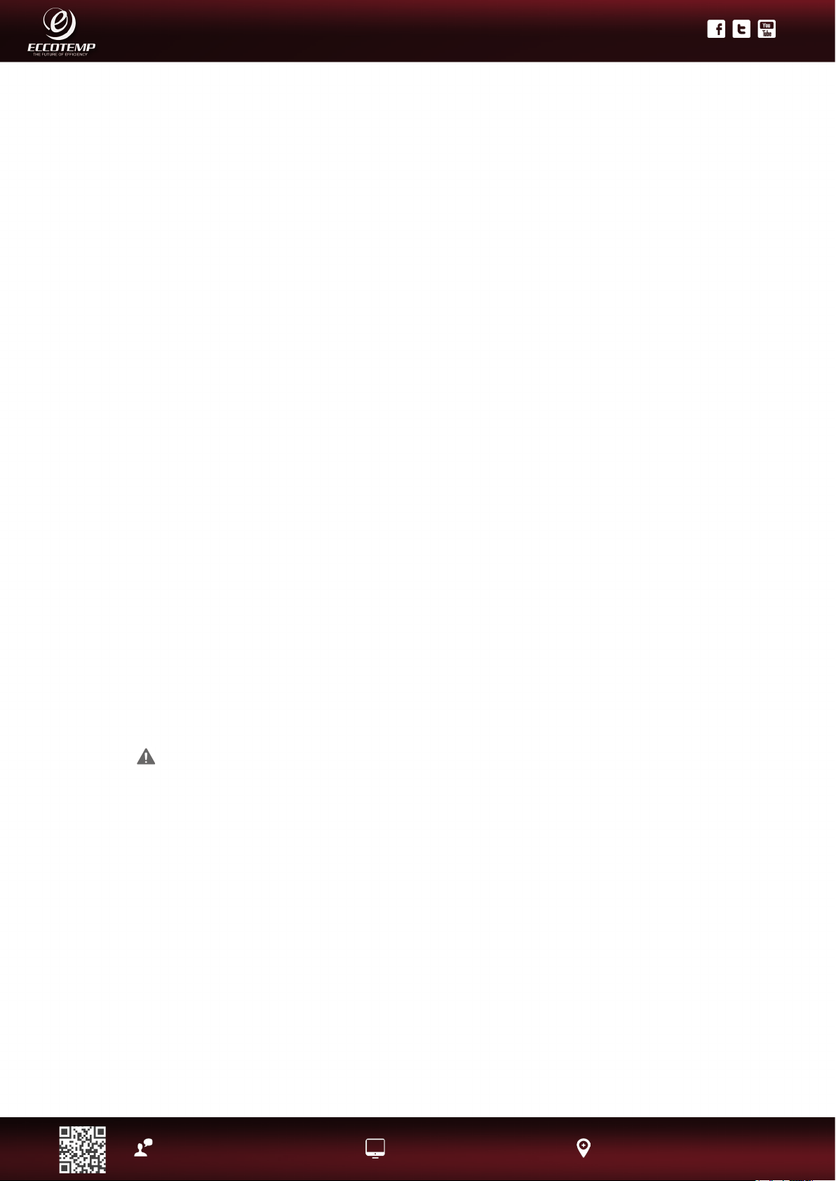
A conned space is one having a volume of less than 50 cubic feet per 1,000
Btuh of the aggregate input of all appliances within that space.
The air must be supplied through two permanent openings of equal area. One is
to be located within 12” above the oor and the other is to be located within 12”
below the ceiling.
The minimum net free area of each opening must not be less than one square
inch per 1,000 Btuh of the total input rating of all the appliances in the enclosure
(but not less than 100 square inches), if each opening communicates with other
unconned areas inside the building.
Buildings of unusually tight construction shall have the combustion and
ventilation air supplied from outdoors, or a freely ventilated attic or crawl
space. If air is supplied from outdoors, directly or through vertical ducts, there
must be two openings located as specied above and each must have a minimum
net free area of not less than one square inch per 4,000 Btuh of the total input rating of all the appliances in
the enclosure.
If horizontal ducts are used to communicate with the outdoors, each opening must have a minimum net
free area of not less than one square inch per 2,000 Btuh of the total input rating of all the appliances in the
enclosure. If ducts are used, the minimum dimensions of rectangular air ducts shall not be less than 4”
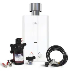
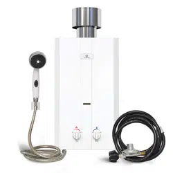
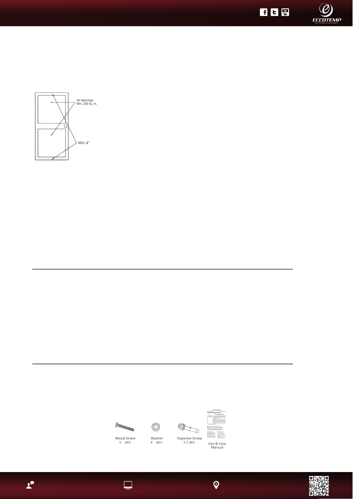
Inspect Shipment
Inspect the water heater for possible damage. Check the markings on the rating plate of the water
heater to be certain the type of gas supplied corresponds to the water heater requirements. Verify
all included parts are present (see below).
NOTICE: If the water heater is installed in an unconned space within a building of conventional
frame, masonry or metal construction, inltration air is normally adequate for proper combustion
and ventilation. If the water heater is installed in a conned space, provisions for combustion and
ventilation air must be made.
NOTICE: If the duct openings which supply combustion and ventilation air are to be covered with a
protective screen or grill, the net free area (openings in the material) of the covering material must
be used in determining the size of the openings. Protective screening for the openings MUST NOT be
smaller than 1/4” esh to prevent clogging by lint or other debris. .
Corrosive Atmospheres
The air in beauty shops, dry cleaning
establishments, photo processing labs, and
storage areas for liquid and powdered bleaches
or swimming pool chemicals often contain such
halogenated hydrocarbons.
An air supply containing halogenated
hydrocarbons may be safe to breathe, but
when it passes through a gas ame corrosive
elements are released that will shorten the life
of any gas burning appliance.
Propellants from common spray cans or gas
leaks from A/ C and refrigeration equipment are
highly corrosive after passing through a ame.
The water heater warranty is voided when
failure of the heater is due to operation in a
corrosive atmosphere.
NOTICE: The water heater should not be
installed near an any air supply containing
halogenated hydrocarbons.
2
2
10
Product Support: Eccotemp.com/help-desk Shop Online: Eccotemp.com/products Store Locater: Eccotemp.com/locater
Phone: 866-356-1992 | Email: [email protected] | Address: 315 - A Industrial RD Summerville, SC 29483
PLEASE NOTE: THIS MANUAL IS SUBJECT TO CHANGE AT ANYTIME, TO ENSURE THIS MANUAL IS UP TO DATE PLEASE VISIT OUR HELPDESK AT WWW.ECCOTEMP.COM
FOR ALL OF OUR PRODUCT MANUALS.
PLEASE NOTE: THIS MODEL IS FOR INDOOR PERMANENT INSTALLATIONS ONLY.
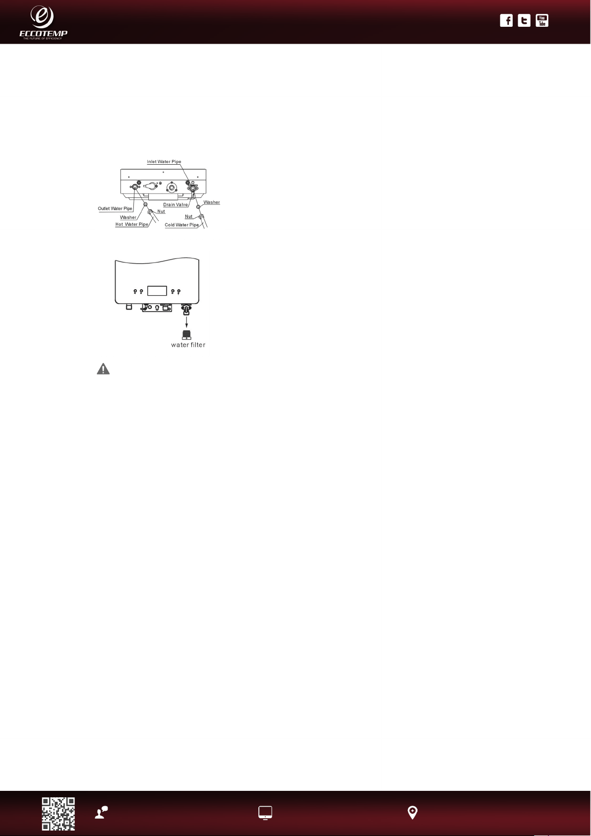
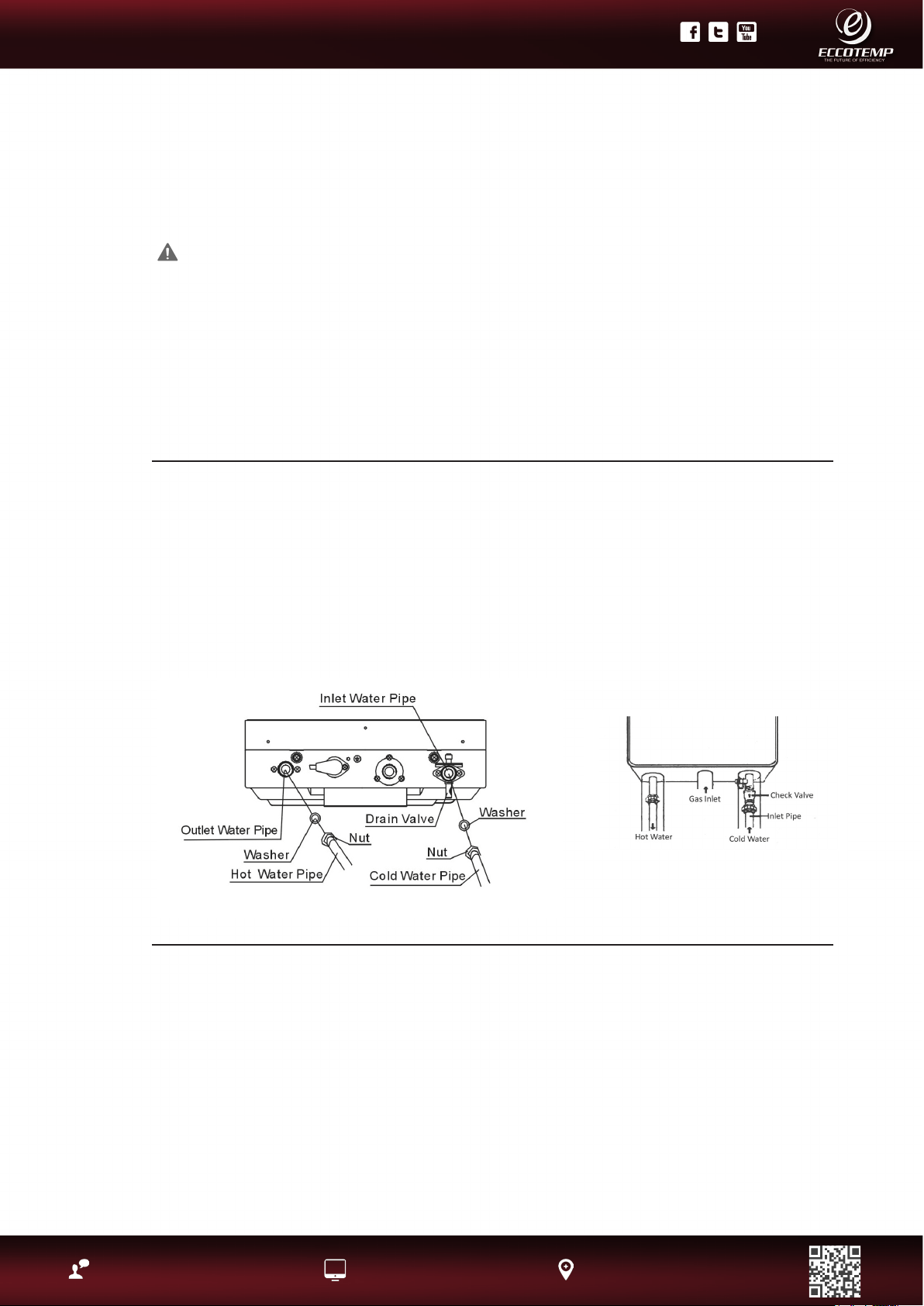
Water Supply Connections....
To conserve energy and to prevent freezing, insulate both cold and hot
water supply lines. DO NOT cover the drain valves. Install a shutoff
valve near the inlet of the water heater for service and draining
purposes. Before connecting the water supply pipe to the water
heater, open the shutoff valve ·and clean out sand, debris, air, caulking
material, etc. inside the pipe. Connect to the water inlet, then check
water ow. Close the shutoff valve and clean the water lter.
If a water heater is installed in a closed water supply system, such as
one having a backow preventer in the cold water supply line, means
shall be provided to control thermal expansion. Contact the water
supplier or local plumbing inspector on how to control this situation.
CAUTION: This water heater must only be used with the following water supply system conditions:
• With clean, potable water free of corrosive chemicals, sand, dirt, or other contaminates.
• With inlet water temperatures above 32°F, but not to exceed 90°F.
• Free of lime and scale deposits.
• DO NOT reverse the hot and cold water connections. The water heater will not operate.
To ensure proper operation of the water heater, the following water pressure guidelines should be
followed:
• Operation of the water heater requires the minimum water pressure of 14 psi and a minimum water
ow rate of 0.75 gpm.
• Additional water pressure is required for long pipe runs and outlet tting(s) water pressure drops.
• To maintain proper performance, ensure sufcient water supply pressure. The Required Water
Pressure = Min. Operating Water Pressure (14 psi) + Pipe Pressure Loss + Faucet and Shower
Pressure Loss + Safety Margin (more than 5 psi).
• To supply hot water to upper oors, additional water pressure (0.44 psi/ft) must be ensured.
• The measurement should be calculated by the distance between the water inlet of the water heater
(ground level) to the hot water faucet (upper oor level).
• Well water systems should be set at a range of 50-60 psi.
• When the water is supplied from a water supply tank, the height of the tank and the diameter of
the pipes and their relation to water pressure, should be taken into consideration. Gravity water
pressure is not recommended.
IMPORTANT: Do not apply heat to the HOT or COLD water connections. Any heat applied to the water
supply ttings will permanently damage the internal components of the water heater.
NOTICE: If the water ow resistance of a shower head is too high, the burner in the water heater will
fail to ignite. Keep the shower head clean from debris that could cause additional pressure drop.
NOTICE: If using mixing valves on the outlet, choose one which prevents cold water pressure from
overcoming hot water line pressure.
DO NOT use pipes with smaller diameters than the water supply connection of the water heater.
Be sure to connect the water inlet and the hot water outlet as shown on the water heater. If reversed,
the water heater will not function.
Installation of unions or exible copper connections are recommended on the HOT and COLD water
lines, so that the water heater may disconnect easily for servicing if necessary.
Plumbing should be carried out by a qualied plumber in accordance with local codes. Use approved
plumbing materials and tools only.
Install a Check Valve between the water heater and the water shutoff valve. (See illustration below).
11
Product Support: Eccotemp.com/help-desk Shop Online: Eccotemp.com/products Store Locater: Eccotemp.com/locater
Phone: 866-356-1992 | Email: [email protected] | Address: 315 - A Industrial RD Summerville, SC 29483
PLEASE NOTE: THIS MANUAL IS SUBJECT TO CHANGE AT ANYTIME, TO ENSURE THIS MANUAL IS UP TO DATE PLEASE VISIT OUR HELPDESK AT WWW.ECCOTEMP.COM
FOR ALL OF OUR PRODUCT MANUALS.
PLEASE NOTE: THIS MODEL IS FOR INDOOR PERMANENT INSTALLATIONS ONLY.
Water Supply Connections Continued....
In regards to the HOT WATER OUTLET:
• Connections between the water heater and point(s) of use should
be as short and direct as possible.
• DO NOT use lead or non-approved plastic pipe.
• To conserve energy and minimize heat loss, insulation of hot
water piping is recommended.
NOTICE: The ow rate of hot water may vary when more than two
faucets (appliances, xtures, etc.) are being used simultaneously.
NOTICE: The pipes MUST be completely drainable. If the hot water
faucets are located at a point higher than the water heater, place a
drain valve at the lowest point (see diagram to the left).
A new pressure relief valve, complying with the Standard for relief Valves and Automatic Gas Shut-Off Devices
for Hot Water Supply Systems, ANSI Z21.22, must be installed at the hot water outlet connection of the water
heater at the time of installation. Local codes shall govern the installation of relief valves.
For safe operation of the water heater, be sure that:
• The pressure rating of the relief valve must not exceed 150 psi, the maximum working pressure of the water
heater as marked on the rating plate.
• The BTUH rating of the relief valve must equal or exceed the BTUH input of the water heater as marked on its
rating plate.
• No valve of any type should be installed between the relief valve and the water heater.
• Discharge from the relief valve should be piped to a suitable drain to eliminate potential water damage. Piping
used should be of a type approved for the distribution of hot water.
• Hot and cold water lines should be insulated up to the water heater.
• The discharge line must be NO SMALLER than the outlet of the valve and must pitch downward to allow
complete drainage (by gravity) of the relief valve and discharge line.
• The end of the discharge line should not be threaded or concealed and should be protected from freezing. No
valve of any type, restriction or reducer coupling should be installed in discharge line.
NOTICE: The diagram below illustrates a pressure only relief valve. If local codes require a combination temperature
and pressure relief valve be installed, an extension piece may be needed.
Relief Valve
NOTICE: Local codes govern the installation of relief
valves. If local codes require that a temperature
and pressure relief valve should be installed the
manufacturer recommends a type 40XL Watts T&P
relief valve or an equivalent model be used.
NOTICE: Manual operation of relief valves should be
performed at least once a year. Turn off the electrical
power and gas shutoff valve. Lift and release lever
on the relief valve and check the manual operation of
the relief valve. You should take precaution to avoid
contact with the hot water coming out of the relief
valve and to prevent water damage.
NOTICE: If the relief valve on the system discharges
periodically, this may be due to thermal expansion
in a closed water supply system. Contact the water
supplier or local plumbing inspector on how to
correct this situation. Do not plug the relief valve.
Display screen
Front cover
Motor fan
Temperature
controller
Heat exchanger
Fixing board
Seal ring
Water flow sensor
Burner assemblu
Ignition pin
Proportion Valve
Flame sensor
Flame
sensor board
Solenoid valve
Gas inlet pipe
Back cover
Power cord
Gas flute
Water inlet pipe
Computer board
Wind switch
Clip
Hot water
temp. sensor
Fixing board
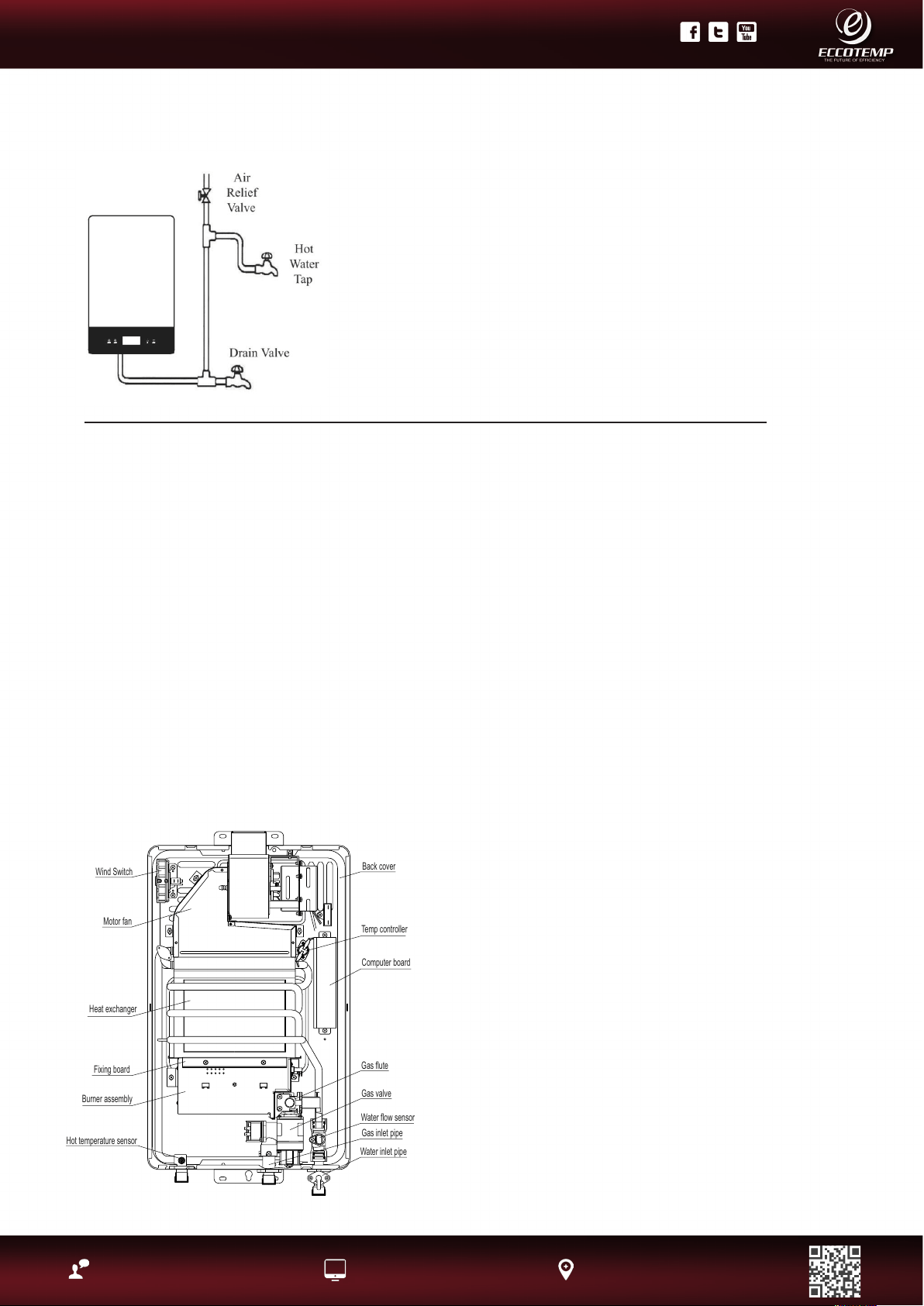
Back cover
Motor fan
Burner assembly
Wind Switch
Heat exchanger
Water flow sensor
Water inlet pipe
Hot temperature sensor
Gas inlet pipe
Gas flute
Temp controller
Computer board
Gas valve
12
Product Support: Eccotemp.com/help-desk Shop Online: Eccotemp.com/products Store Locater: Eccotemp.com/locater
Phone: 866-356-1992 | Email: [email protected] | Address: 315 - A Industrial RD Summerville, SC 29483
PLEASE NOTE: THIS MANUAL IS SUBJECT TO CHANGE AT ANYTIME, TO ENSURE THIS MANUAL IS UP TO DATE PLEASE VISIT OUR HELPDESK AT WWW.ECCOTEMP.COM
FOR ALL OF OUR PRODUCT MANUALS.
PLEASE NOTE: THIS MODEL IS FOR INDOOR PERMANENT INSTALLATIONS ONLY.
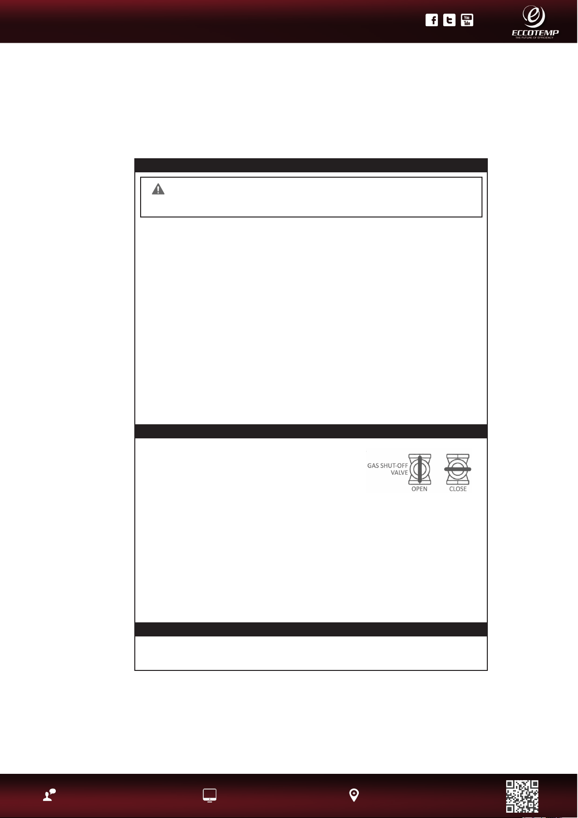
The supplied Manual Gas
Appliance Shutoff Valve
must be installed at the
gas connection of the
water heater at the time of
installation (see diagram to
the left).
The branch gas supply line to
the water heater should be
clean black steel pipe or other
approved gas piping material.
A ground joint union or ANSI
design certied semi-rigid
or exible gas appliance
connector should be installed
in the gas line close to the
water heater.
The National Fuel Gas
Code (NFGC) mandates a
manual gas shut-off valve:
See (NFGC) for complete
instructions.
A sediment trap should be installed at the
bottom of the gas line.
The inlet gas pressure to the water heater
must not exceed 10.5“ w.c. for natural
or 14” w.c. for LP gas. For purposes of
input adjustment, the minimum inlet gas
pressure (with main burner on) is shown on
the water heater rating plate. If high or low
gas pressures are present, contact your
gas supplier for correction
The appliance and its individual shutoff
valve must be disconnected from the gas
supply piping system during any pressure
testing of that system at test pressures
in excess of ½ psi (3.5 kPa). The appliance
must be isolated from the gas supply piping
system by closing its individual manual
shutoff valve during any pressure testing
of the gas supply piping system at test
pressures equal to or less than ½ psi (3.5
kPa).
The appliance must be isolated from the
gas supply piping system by closing its
individual manual shutoff valve during any
pressure testing of the gas supply piping
system at test pressures equal to or less
than ½ psi (3.5 kPa).
WARNING:
Never use an open
ame to test
for gas leaks, as
property damage,
personal injury, or
death could result.
Gas Supply
WARNING: Do not attempt to convert this water heater for use with a different type of gas other than the
type shown on the rating plate. Such conversion could result in hazardous operating conditions. Please have a
professional connect the gas pipe.
The water heater and its gas connections must be leak tested at normal
operating pressures before it is placed in operation.
• Turn on the gas shut-off valve(s) to the water heater.
• Use a commercial leak detector or soapy water solution to test for leaks
at all connections and ttings. Bubbles indicate a gas leak that must be
corrected.
All connections should also be leak tested after the water heater is placed
in operation.
DO NOT use excessive force (over 31.5 ft lbs.) in
tightening the pipe, particularly if pipe compound is
used, as the unit may be damaged.
Compound used on the threaded joints of the gas
piping must be of the type resistant to the action of
LP gas. Use compound sparingly and use on male
threads only.
Pressure Testing the Gas Supply System
WARNING: Install a gas pressure regulator, in the gas supply line, which does not
exceed the maximum supply pressure. DO NOT use an industrial type gas regulator.
The water heater must be isolated from the gas piping system by closing the manual gas
shut-off valve during any pressure testing of the gas supply piping at pressures equal to or
less than 1/2 psi (14’w.c.) .
High Altitude
Ratings of gas appliances are based on sea level operation and need not be changed for installations
at elevations up to 2,000 feet. Unit not recommended for elevations in excess of 2,000 feet
Leak Testing
13
Product Support: Eccotemp.com/help-desk Shop Online: Eccotemp.com/products Store Locater: Eccotemp.com/locater
Phone: 866-356-1992 | Email: [email protected] | Address: 315 - A Industrial RD Summerville, SC 29483
PLEASE NOTE: THIS MANUAL IS SUBJECT TO CHANGE AT ANYTIME, TO ENSURE THIS MANUAL IS UP TO DATE PLEASE VISIT OUR HELPDESK AT WWW.ECCOTEMP.COM
FOR ALL OF OUR PRODUCT MANUALS.
PLEASE NOTE: THIS MODEL IS FOR INDOOR PERMANENT INSTALLATIONS ONLY.
NOTICE: The National Fuel Gas Code (NFGC) mandates a manual gas shut- off valve: See (NFGC)
for complete instructions. Local codes or plumbing authority requirements may vary from the
instructions or diagrams provided and take precedent over these instructions.
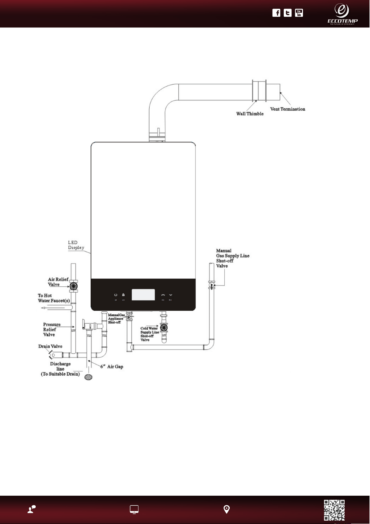
Installing the water heater.
Typical Installation ( Some Items May Not Apply)
(Not Supplied)

14
Product Support: Eccotemp.com/help-desk Shop Online: Eccotemp.com/products Store Locater: Eccotemp.com/locater
Phone: 866-356-1992 | Email: [email protected] | Address: 315 - A Industrial RD Summerville, SC 29483
PLEASE NOTE: THIS MANUAL IS SUBJECT TO CHANGE AT ANYTIME, TO ENSURE THIS MANUAL IS UP TO DATE PLEASE VISIT OUR HELPDESK AT WWW.ECCOTEMP.COM
FOR ALL OF OUR PRODUCT MANUALS.
PLEASE NOTE: THIS MODEL IS FOR INDOOR PERMANENT INSTALLATIONS ONLY.
Indoor unit must be installed with CAT 3
vent pipe in accordance with vent supplier/
Manufacturer in accordance with local code.
A. BACK INSTALLATION
1. Insert the vent pipe through the installation
holes in the wall with the terminal sticking
out.
2. Connect the elbow to the vent pipe and
water heater, moving straight backwards
until the expansion screws go into the holes
of the water heater. Screw the nuts tight (pay
attention to the direction of the elbow).
B. SIDE INSTALLATION:
1. Aim the holes in the water heater onto the
expansion screws, hang it up and screw the
nuts tightly.
2. Put the vent pipe through the holes in the
wall, and connect the elbow with the water
heater and vent pipe.
C. VERTICAL INSTALLATION
Please refer to local installation professional
or venting manufacturer:
The installation hole in the wall needs to be
sealed by re-retardant material or wall
thimble, making sure the water heater is tight
and will not come off.
Mounting the Water Heater
Make sure the location of the appliance allows for easy access and
operation.
In case of dry wall or concrete wall use dry wall anchors or lag bolts.
The water heater requires 120VAC/ 60Hz. Have a receptacle with
ground terminal near the water heater. The length of the power
supply cord is 5 feet.
Drill the holes as per the sizes in the gure to the left, put 2
expansion screws into the top holes, and 2 rubber screws into the
bottom holes.
Hang up the water heater unit, tighten the expansion screws, and
put 2 wood thread screws into the bottom holes.
CAUTION: Reinforcement of the wall is
required in case the wall is not strong enough to
hold the appliance.
15
Product Support: Eccotemp.com/help-desk Shop Online: Eccotemp.com/products Store Locater: Eccotemp.com/locater
Phone: 866-356-1992 | Email: [email protected] | Address: 315 - A Industrial RD Summerville, SC 29483
PLEASE NOTE: THIS MANUAL IS SUBJECT TO CHANGE AT ANYTIME, TO ENSURE THIS MANUAL IS UP TO DATE PLEASE VISIT OUR HELPDESK AT WWW.ECCOTEMP.COM
FOR ALL OF OUR PRODUCT MANUALS.
PLEASE NOTE: THIS MODEL IS FOR INDOOR PERMANENT INSTALLATIONS ONLY.
Venting
The installation of venting must
comply with national codes, local
codes, and the vent manufacturer’s
instructions.
The water heater must be vented
to the outdoors as described
in these instructions. DO NOT
connect this water heater to an
existing Vent or Chimney, it must
be vented separately from all other
appliances.
All vent components (adapters,
pipe, elbows, terminals, etc.) should
be UL 1738 Certied Stainless Steel
Venting Material (e.g. AL29-4C).
The specied vent termination
must be used. The termination
should be a 90° elbow type with
screen. (Refer to page 19).
Use a vent pipe with an anti-
disconnection structure.
The use of a High Temperature
Silicone (500’ F) may be required
to seal vent connections. To
prevent accidental gas exhaust
leakage, apply a 1/4” wide bead
approximately 1/4” from the end
and another bead against the joint
side of the stop bead.
Follow vent manufacturer’s
installation instructions.
The unit can be vented either
horizontally or vertically.
Vent pipe runs must be adequately
supported along both horizontal
and vertical runs.
The maximum recommended
unsupported span should be no
more than ve (5) feet. Support
isolation hanging bands should
be used. DO NOT use wire. (See
diagram below).
DANGER: Failure to
install the vent adapter
and properly vent the
water heater to the
outdoors as outlined in
the Venting section of
this manual will result
in unsafe operation
of the water heater
causing death, serious
injury, explosion, or
re. To avoid the risk
of re, explosion,or
asphyxiation from
carbon monoxide,
NEVER operate the
water heater unless
it is properly vented
and has adequate air
supply for proper
operation as outlined in
the Venting section of
this manual.
WARNING: Use
approved Category III
Stainless Steel vent
material only. No
other vent material is
permitted.
Owner must refer to
vent manufacturer’s
instructions and
specications. Z-Flex
information can
be found at www.
novaex.com, see page
19 for additional links.
WARNING:
Refer to pages 17-
18 for clearances to
combustible material.
Installing the water heater
Venting Through Closed Spaces
If the vent piping passes through a closed space, wrap the vent pipe with inammable insulation material
that is at least 3/4” thick. DO NOT let the insulation material make contact with ammable materials. A
minimum clearance of 6” between the vent pipe and ceiling should be maintained. Follow local codes.
For maintenance and inspection purposes, the following holes are required to be made:
• Two (2) inspection openings that allow access to venting. One
(1) of these openings should be close to where the vent pipe
enters the ceiling. The other opening should be near the vent
termination.
• A ventilation hole with a 16 sq. in. opening should be made at
least every 10 feet.
NOTICE: Vent pipes must be completely insulated with
inammable material when installed in alcoves, closets, and
garages and must not touch any ammable material.
16
Product Support: Eccotemp.com/help-desk Shop Online: Eccotemp.com/products Store Locater: Eccotemp.com/locater
Phone: 866-356-1992 | Email: [email protected] | Address: 315 - A Industrial RD Summerville, SC 29483
PLEASE NOTE: THIS MANUAL IS SUBJECT TO CHANGE AT ANYTIME, TO ENSURE THIS MANUAL IS UP TO DATE PLEASE VISIT OUR HELPDESK AT WWW.ECCOTEMP.COM
FOR ALL OF OUR PRODUCT MANUALS.
PLEASE NOTE: THIS MODEL IS FOR INDOOR PERMANENT INSTALLATIONS ONLY.
Installing the water heater, Continued....
Venting Lengths
MAXIMUM VENT LENGTH
The system will not operate if there is excessive restriction
(pressure drop) in the venting system. A maximum of 32 feet of
vent pipe may be used provided there is only one 90° elbow in the
system. If additional elbows are required: two elbows can be used
with 27 feet, and three elbows can be used with 22 feet of vent
pipe.
A 90° elbow is equivalent to 5 feet of straight pipe. A 45° elbow is
equivalent to 2 feet 6 inches of straight pipe .
The termination elbow does not count as an elbow when
determining total vent lengths.
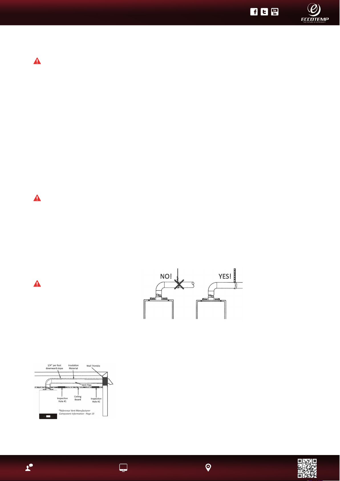
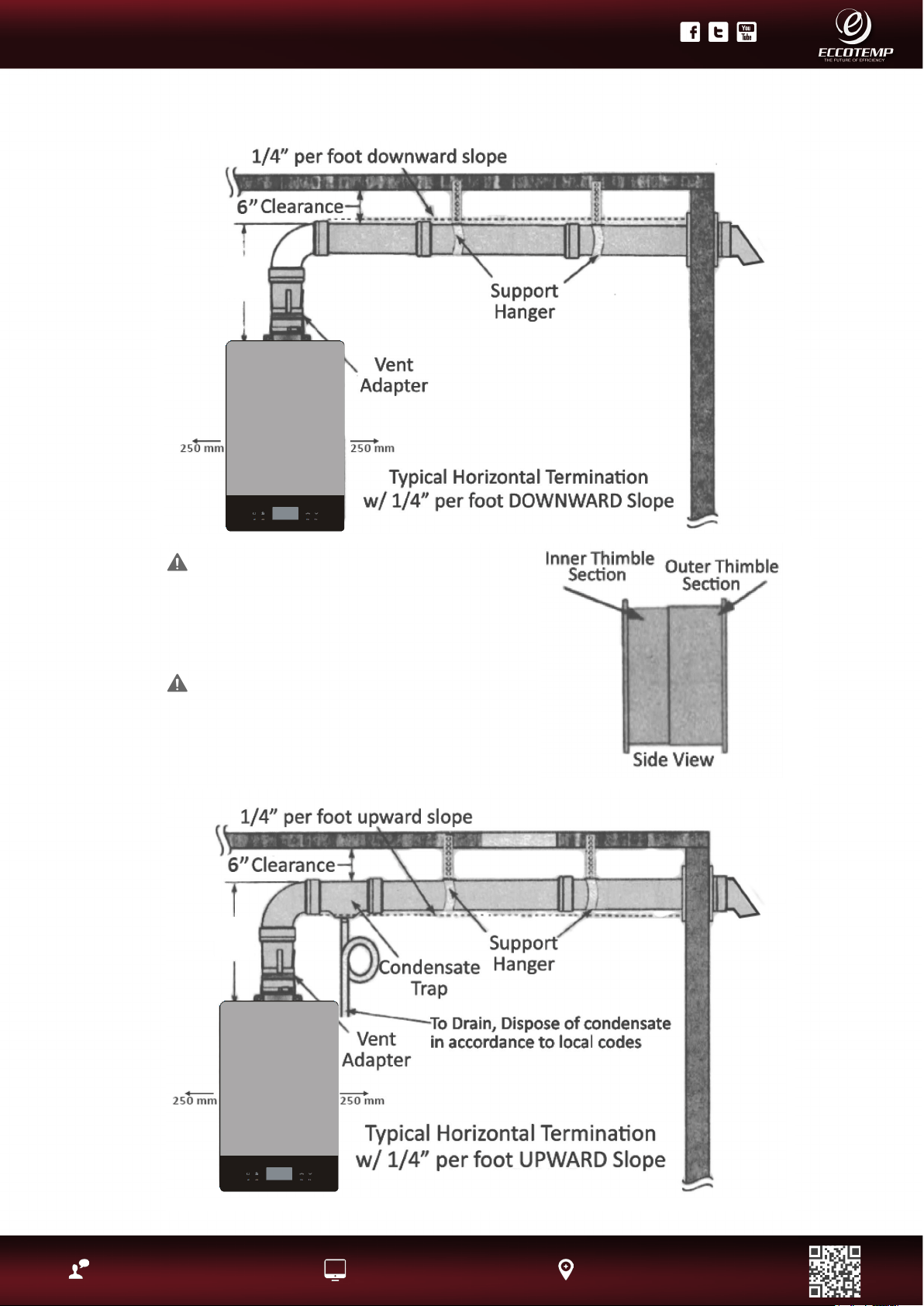
The vent must be installed with a slight downward slope of 1/ 4”
per foot of horizontal run toward the vent terminal (see diagram
below). This ensures that any condensate formed during operation
of the unit is evacuated from the appliance
A 1/4” per foot upward slope is acceptable when it is not possible
to vent with a downward slope, however, a approved Category III
Stainless Steel condensate trap MUST be installed at the beginning
of the horizontal run (See page 20 “Typical Horizontal Termination
w/ 1/4” per foot UPWARD Slope” or page 14, “Standard Vertical
Vent Termination” for examples).
Number of
90° elbows
(bends)
Maximum
Length of
Straight Pipe
1
2
3
32’
27’
22’
One (1) 90° Elbow is
Equivalent to 5 Feet of
Straight Pipe
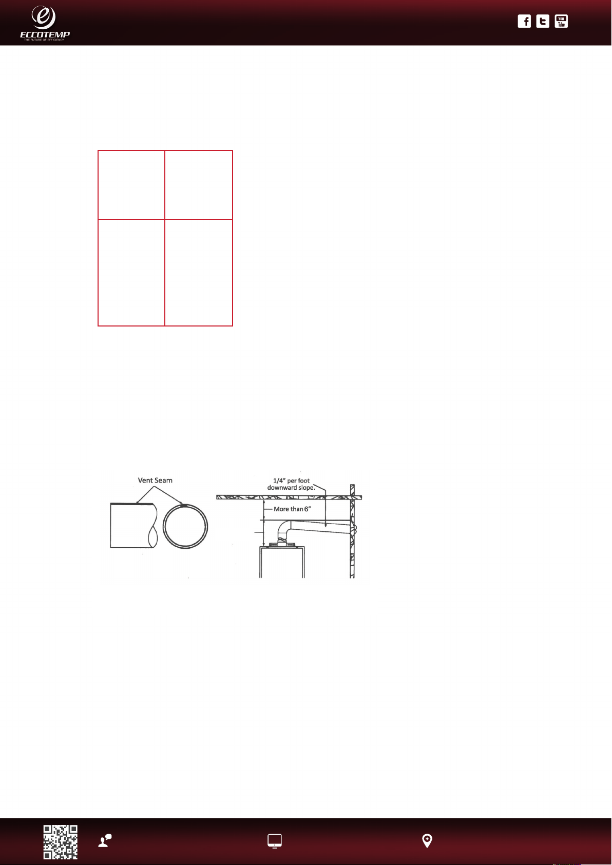
MINIMUM VENT LENGTH
The venting may be as short as 12”,
provided one vent termination is
installed to the outdoors through a
sidewall, one 90°elbow is included in
the installation, and the wall thimble
is installed.
NOTICE: Make sure that the seam
of the vent pipe in horizontal runs
is toward the top of the installation
(see illustration to the left)
Draining the Condensate
In certain conditions, installations in unconditioned space or having long horizontal or vertical runs
may accumulate condensate.
Condensate is known to be acidic; refer to local, state (provincial) or federal codes for proper
handling methods.
In order to prevent condensate from draining back into the water heater, we recommend a
condensate trap and drain to be installed in a horizontal vent section as close as practical to the
water heater vent connection.
Not following proper condensate procedures will void warranty.
12 in. minimum
17
Product Support: Eccotemp.com/help-desk Shop Online: Eccotemp.com/products Store Locater: Eccotemp.com/locater
Phone: 866-356-1992 | Email: [email protected] | Address: 315 - A Industrial RD Summerville, SC 29483
PLEASE NOTE: THIS MANUAL IS SUBJECT TO CHANGE AT ANYTIME, TO ENSURE THIS MANUAL IS UP TO DATE PLEASE VISIT OUR HELPDESK AT WWW.ECCOTEMP.COM
FOR ALL OF OUR PRODUCT MANUALS.
PLEASE NOTE: THIS MODEL IS FOR INDOOR PERMANENT INSTALLATIONS ONLY.
Installing the water heater, Continued....
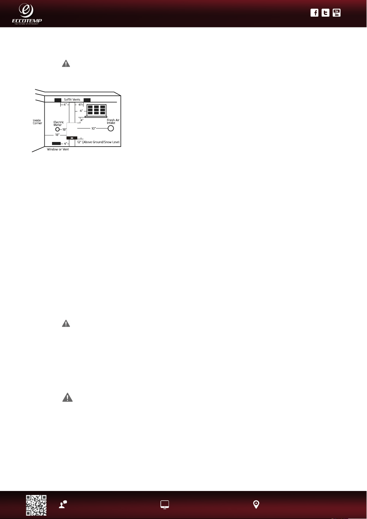
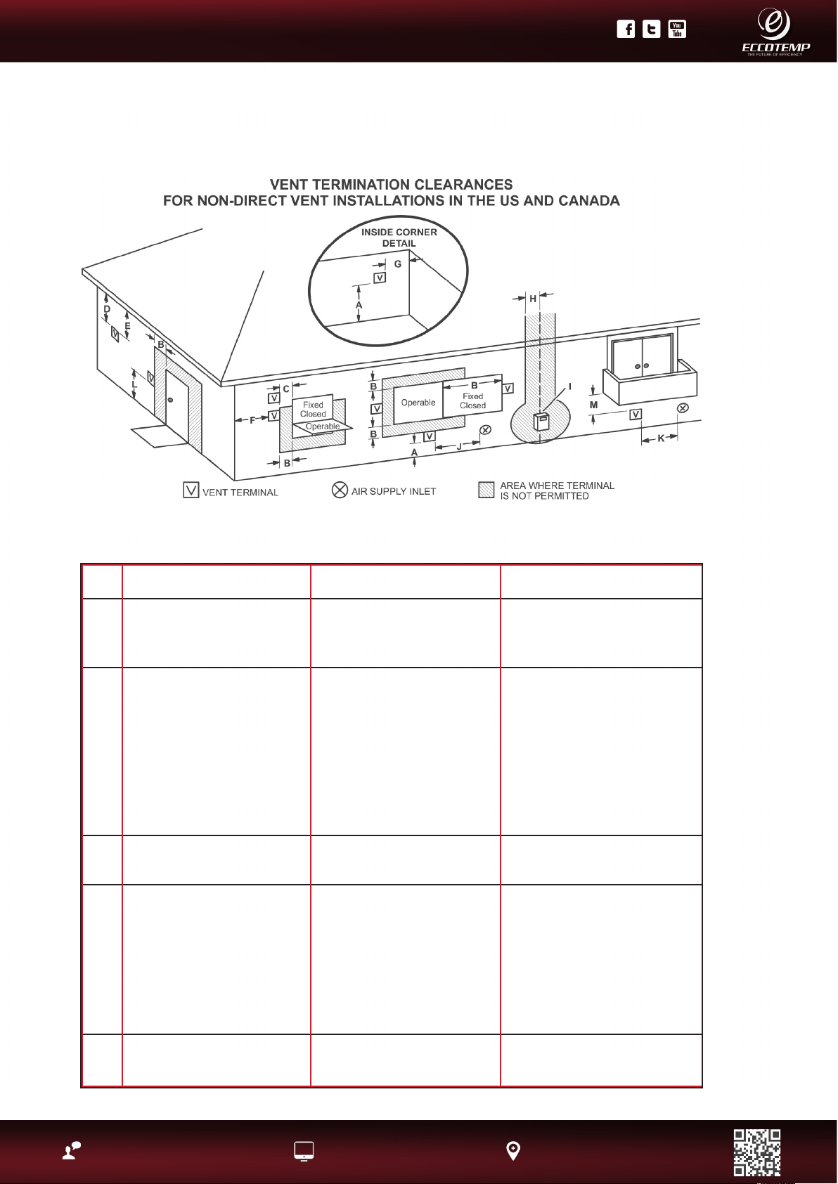
US Installations1 Canadian Installations2
A = Clearance above grade,
veranda, porch, deck, or
balcony
12 in (30 cm) 12 in (30 cm)
B = Clearance to window or
door that may be opened
4 ft (1.2 m) below or to side
of opening; 1 ft (300 mm)
above opening
6 in (15 cm) for appliances ≤
10,000 Btuh (3 kW), 12 in (30
cm) for appliances > 10,000
Btuh (3 kW) and ≤ 100,000
Btuh (30 kW), 36 in
(91 cm) for appliance >
100,000 Btuh (30 kW)
C = Clearance to permanently
closed window
*
D = Vertical clearance to
ventilated soft located
above the terminal within
a horizontal distance of
2 feet (61 cm) from the
center line of the terminal
*
E = Clearance to unventilated
soft
*
18
Product Support: Eccotemp.com/help-desk Shop Online: Eccotemp.com/products Store Locater: Eccotemp.com/locater
Phone: 866-356-1992 | Email: [email protected] | Address: 315 - A Industrial RD Summerville, SC 29483
PLEASE NOTE: THIS MANUAL IS SUBJECT TO CHANGE AT ANYTIME, TO ENSURE THIS MANUAL IS UP TO DATE PLEASE VISIT OUR HELPDESK AT WWW.ECCOTEMP.COM
FOR ALL OF OUR PRODUCT MANUALS.
PLEASE NOTE: THIS MODEL IS FOR INDOOR PERMANENT INSTALLATIONS ONLY.
F = Clearance to outside corner *
G = Clearance to inside corner *
H = Clearance to each side of
center line extended above
meter /regulator assembly
* 3 ft (91 cm) within a height 15
ft above the meter/regulator
assembly
I = Clearance to service
regulator vent outlet
* 3 ft (91 cm)
J = Clearance to non-
mechanical air supply
inlet to building or the
combustion air inlet to any
other appliance
4 ft (1.2 m) below or to side
of opening; 1 ft (300 mm)
above opening
6 in (15 cm) for appliances ≤
10,000 Btuh (3 kW), 12 in (30
cm) for appliances > 10,000
Btuh (3kW) and ≤ 100,000
Btuh (30 kW), 36 in (91 cm)
for appliances >
100,000 Btuh (30 kW)
K = Clearance to a mechanical
air supply inlet
3 ft (91 cm) above if within
10 ft (3 m) horizontally
6 feet (1.83 m)
L = Clearance above paved
sidewalk or paved driveway
located on public property
* 7 ft (2.13 m)
M = Clearance under veranda,
porch, deck or balcony
* 12 in (30)
* For clearances not specied in ANSI Z223.1 / NFPA 54 or CSA-B149.1, one of the following shall be indicated:
A) A minimum clearance value determined by testing in accordance with Clause 5.20, or;
B) A reference to the following footnote:
“Clearance in accordance with local installation codes and the requirements of the gas supplier.”
• A vent shall not terminate directly above a sidewalk or paved driveway that is located between
two single family dwellings and serves both dwellings.
• Permitted only if veranda, porch, deck, or balcony is fully open on a minimum of two sides beneath
the oor.
Notes:
1. In accordance with the current CSA B149.1 Natural Gas and Propane Installation Code
2. In accordance with the current ANSI Z223.1 / NFPA 54 National Fuel Gas Cod
19
Product Support: Eccotemp.com/help-desk Shop Online: Eccotemp.com/products Store Locater: Eccotemp.com/locater
Phone: 866-356-1992 | Email: [email protected] | Address: 315 - A Industrial RD Summerville, SC 29483
PLEASE NOTE: THIS MANUAL IS SUBJECT TO CHANGE AT ANYTIME, TO ENSURE THIS MANUAL IS UP TO DATE PLEASE VISIT OUR HELPDESK AT WWW.ECCOTEMP.COM
FOR ALL OF OUR PRODUCT MANUALS.
PLEASE NOTE: THIS MODEL IS FOR INDOOR PERMANENT INSTALLATIONS ONLY.
Installing the water heater, Continued....
WARNING: Use UL approved Category III vent material
only. No other vent material is permitted. Owner must refer
to vent manufacturer’s instructions and specications.
Z-Flex information can be found at www.novaex.com,
refer to page 19 for additional links.
CAUTION: Follow the vent manufacturers installation
instructions as design might vary from manufacturer to
manufacturer.
12 in.
minimum
12 in.
minimum
20
Product Support: Eccotemp.com/help-desk Shop Online: Eccotemp.com/products Store Locater: Eccotemp.com/locater
Phone: 866-356-1992 | Email: [email protected] | Address: 315 - A Industrial RD Summerville, SC 29483
PLEASE NOTE: THIS MANUAL IS SUBJECT TO CHANGE AT ANYTIME, TO ENSURE THIS MANUAL IS UP TO DATE PLEASE VISIT OUR HELPDESK AT WWW.ECCOTEMP.COM
FOR ALL OF OUR PRODUCT MANUALS.
PLEASE NOTE: THIS MODEL IS FOR INDOOR PERMANENT INSTALLATIONS ONLY.
HARDWIRING THE ELECTRICAL
CONNECTIONS:
• Wiring should be carried out by a qualied
electrician in accordance with local codes.
• The water heater requires 120 VAC/60Hz
and should be properly grounded.
• DO NOT connect grounding wire to water
pipes, gas pipes, telephone cables, lightning
conductor circuits and to grounding circuit
of other equipment that carry a ground-fault
interrupter.
• An ON/OFF switch must be provided and
installed for the incoming 120VAC power.
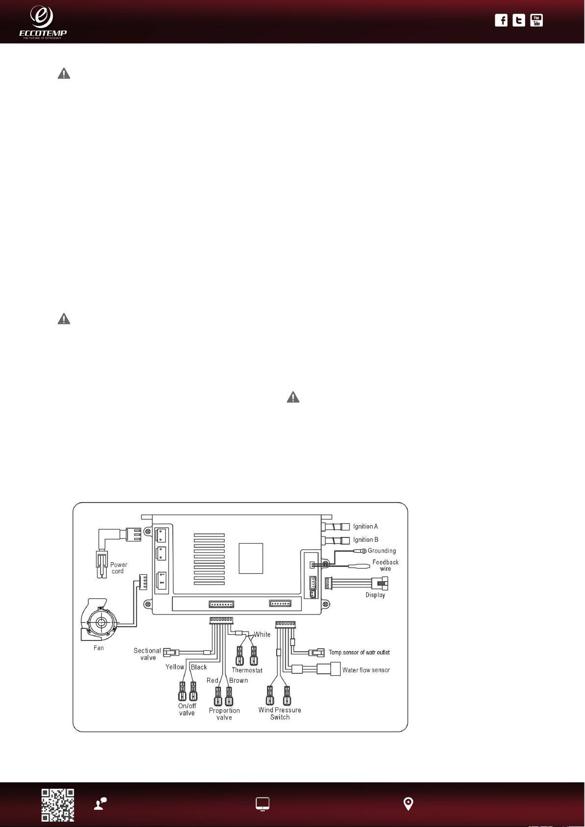
• Wire the water heater exactly as shown
below. A wiring diagram is also found inside
of the cover panel.
• A green screw is provided in the junction
box for grounding connection.
• Connect the live wire to black leg wire and
the neutral wire to the white neutral wire.
Electrical Connection
POWER CORD:
• The electric power supply requirement for
this water heater is 120 VAC/60HZ, 2 Amps.
• The water heater comes with a three (3) pin
power supply cord. Use only a power outlet
with a ground terminal.
• The installation of an electric leakage
breaker is recommended. (GFCI)
• Keep any excess of the power supply cord
on the outside of the water heater.
• If local codes require hardwiring, see
instructions for “Hardwiring the Electrical
Connections”.
WARNING :Field wiring connections and electrical grounding must comply with local codes.
WARNING: Shock hazard line voltage is
present. Before servicing the water heater, turn
off the electrical power to the water heater at the
main disconnect or circuit breaker. Failure to do so
could result in severe personal injury or death.
CAUTION: Label all wires prior to
disconnection when servicing controls. Wiring
errors can cause improper and dangerous
operation. Verify correct operation after servicing.
Electric Wiring Diagram
21
Product Support: Eccotemp.com/help-desk Shop Online: Eccotemp.com/products Store Locater: Eccotemp.com/locater
Phone: 866-356-1992 | Email: [email protected] | Address: 315 - A Industrial RD Summerville, SC 29483
PLEASE NOTE: THIS MANUAL IS SUBJECT TO CHANGE AT ANYTIME, TO ENSURE THIS MANUAL IS UP TO DATE PLEASE VISIT OUR HELPDESK AT WWW.ECCOTEMP.COM
FOR ALL OF OUR PRODUCT MANUALS.
PLEASE NOTE: THIS MODEL IS FOR INDOOR PERMANENT INSTALLATIONS ONLY.
Insulation blankets, available to
the general public, for external
use on gas water heaters are
not necessary. The purpose of an
insulation blanket is to reduce the
standby heat loss encountered with
storage tank heaters. This water
heater does not store water making
an insulation blanket unnecessary.
The manufacturer’s warranty does
not cover any damage or defect
caused by installation, attachment
or use of any type of energy saving
or other unapproved devices
(other than those authorized by
the manufacturer) into, onto or in
conjunction with the water heater.
The use of unauthorized energy
saving devices may shorten the
life of the water heater and may
endanger life and property.
The manufacturer disclaims any
responsibility for such loss or injury
resulting from the use of such
unauthorized devices.
WARNING: If
local codes require
external application of
insulation blanket kits
the manufacturer’s
instructions included
with the kit must be
carefully followed.
Insulation Blankets
Hot and Cold Pipe
Insulation Installation
For increased energy efciency,
use pipe insulation. Please install
the insulation, according to the
illustrations above, making sure to
insulate all the way to the top. Do not
cover any drain or pressure valve(s).
Pipe Installation
Inlet Pipe and Outlet Pipe Installation
Use pressure resistant pipe to connect the inlet and outlet
water pipes of the water heater and the local water pipe
(Make sure to place the rubber ring).Before connecting the
inlet water pipe, ush the inside of the pipe. use sealant to
prevent leaks
NOTICE: The hot and cold pipes should
be insulated as shown help to provide
additional freeze protection
During Installation of this water heater
Do’s
• DO check inlet gas pressure to ensure that it is within the range specied on the rating plate.
• DO provide adequate air for combustion and ventilation as discussed in the Use & Care Manual and the
National Gas Code (CAN/CGA B 149 in Canada).
• DO maintain proper clearances to combustibles as specied by applicable code.
• DO ensure that the ue terminal location complies with the guidelines found in the Use & Care Manual and
National Fuel Gas Code (CAN/CGA B 149 in Canada).
Dont’s
• DON’T block or restrict Air Intake Opening located on the back side of the water heater.
• DON’T remove the front cover unless absolutely necessary. This should only be done after being examined by a
qualied service technician.
• DON’T install this product where standing water may occur.

22
Product Support: Eccotemp.com/help-desk Shop Online: Eccotemp.com/products Store Locater: Eccotemp.com/locater
Phone: 866-356-1992 | Email: [email protected] | Address: 315 - A Industrial RD Summerville, SC 29483
PLEASE NOTE: THIS MANUAL IS SUBJECT TO CHANGE AT ANYTIME, TO ENSURE THIS MANUAL IS UP TO DATE PLEASE VISIT OUR HELPDESK AT WWW.ECCOTEMP.COM
FOR ALL OF OUR PRODUCT MANUALS.
PLEASE NOTE: THIS MODEL IS FOR INDOOR PERMANENT INSTALLATIONS ONLY.
Installing the water heater
Installation Check List
A. Water Heater Location
Installed INDOORS.
• Close to area of mostly used outlet.
• Protected from freezing temperatures.
• Proper clearance from combustible surfaces observed.
• Sufcient fresh air supply for proper operation of water heater.
• Air supply free of corrosive elements and ammable vapors.
• Provisions made to protect area from water damage.
• Sufcient room to service heater.
• Combustible materials, such as clothing, cleaning materials, rags, etc. clear of the heater and vent piping.
• Water heater is properly attached to the wall.
B. Water Supply
• Water supply has sufcient pressure.
• Air purged from water heater and piping.
• Water connections tight and free of leaks
• Water lter is clean and in place.
• Materials used are as instructed in this manual.
• Water pipes are insulated.
C. Gas Supply
• Gas type matches rating plate.
• Gas supply pressure is sufcient for the water heater.
• Gas line equipped with shut-off valve, union and sediment trap.
• Approved pipe joint compound used.
• Commercial leak detector or soap and water solution used to check all connections and ttings for
possible gas leak.
• Gas Company inspected installation (if required).
D. Relief Valve
• Pressure Relief Valve properly installed and discharge line run to open drain
• Discharge line protected from freezing.
E . Electrical Wiring
• Voltage matches rating plate.
• Water heater is properly grounded .
• Wiring meets all local codes.
• GFCI Protection where required.
23
Product Support: Eccotemp.com/help-desk Shop Online: Eccotemp.com/products Store Locater: Eccotemp.com/locater
Phone: 866-356-1992 | Email: [email protected] | Address: 315 - A Industrial RD Summerville, SC 29483
PLEASE NOTE: THIS MANUAL IS SUBJECT TO CHANGE AT ANYTIME, TO ENSURE THIS MANUAL IS UP TO DATE PLEASE VISIT OUR HELPDESK AT WWW.ECCOTEMP.COM
FOR ALL OF OUR PRODUCT MANUALS.
PLEASE NOTE: THIS MODEL IS FOR INDOOR PERMANENT INSTALLATIONS ONLY.
Lighting the Water Heater
Before operating this water heater, be sure to read and follow the instructions on the label pictured below and
all other labels on the water heater, as well as the warnings printed in this manual. Failure to do so can result in
unsafe operation of the water heater resulting in property damage, personal injury, or death.
Should you have any problems reading or following the instructions in this manual. STOP, and get help from a
qualied person.
WARNING: If you do not follow these instructions exactly, a re or explosion
may result causing property damage, personal injury or loss of life.
FOR YOUR SAFETY BEFORE USING THE WATER HEATER
OPERATING INSTRUCTIONS
TO TURN OFF GAS TO APPLIANCE
A. This appliance does not have a pilot. It is equipped with an ignition device which automatically
lights the burner. Do not try to light the burner by hand.
B. BEFORE OPERATING smell all around the appliance area for gas. Be sure to smell next to the
oor because some gas is heavier than air and will settle on the oor. Test all connections with a
commercial leak detector or soapy water.
WHAT TO DO IF YOU SMELL GAS
• DO NOT try to light any appliance • DO NOT touch any electric switch; DO NOT use any phone
in your building. • Immediately call your gas supplier from a neighbor’s phone. Follow the gas
supplier’s instructions. • If you cannot reach your gas supplier or re department. • DO NOT return
to your home until authorized by the gas supplier or re department.
C. Use only your hand to push in or turn the gas control knob. Never use tools. If the knob will not
push in or turn by hand, don’t try to repair it, call a qualied service technician. Force or attempted
repair may result in a re or explosion.
D. DO NOT use this appliance if any part has been under water. Immediately call a qualied service
technician to inspect the appliance and to replace any part of the control system and any gas
control which has been under water.
1. STOP! Read the safety information above on this label.
2. Turn off all electric power to the appliance.
3. Set the thermostat to lowest setting.
4. DO NOT attempt to light the burner by hand.
5. Turn the Gas Shut-off Valve located on the outside of the unit clockwise to the “OFF” position.
6. Turn off all electrical power to the appliance
7. Wait ve (5) minutes to clear out any gas. If you smell gas, STOP! Follow “B” in the safety
information above on this label. If you don’t smell gas, go to the next step.
8. Turn the Gas Shutoff Valve located on outside of the unit counterclockwise to the “ON” position.
9. Turn on all electric power to the appliance.
10. Set thermostat to desired setting.
11. If the appliance will not operate, follow the instructions “To Turn Off Gas To Appliance” and call
your service technician or gas supplier.
1. Turn off all electric power to the appliance if service is to be performed.
2. Turn the Gas Shut-off Valve located on the outside of the unit clockwise to the “OFF” position.
24
Product Support: Eccotemp.com/help-desk Shop Online: Eccotemp.com/products Store Locater: Eccotemp.com/locater
Phone: 866-356-1992 | Email: [email protected] | Address: 315 - A Industrial RD Summerville, SC 29483
PLEASE NOTE: THIS MANUAL IS SUBJECT TO CHANGE AT ANYTIME, TO ENSURE THIS MANUAL IS UP TO DATE PLEASE VISIT OUR HELPDESK AT WWW.ECCOTEMP.COM
FOR ALL OF OUR PRODUCT MANUALS.
PLEASE NOTE: THIS MODEL IS FOR INDOOR PERMANENT INSTALLATIONS ONLY.
Operating the Water Heater.
Turning on the Water Heater
1. Make sure the gas type you will use is same as the type on the data plate.
2. Turn on the main gas valve, plug in the power cord (be sure the socket is well grounded), and
press the “ON/OFF”button on the control panel. Set temperature to 120° F.
3. when you need to set the temperature up to 122F, press the children lock for 3 seconds and
the light will be off, then you can set higher temperature.
4. Turn on the faucet, and the fan will begin working. You will hear the ignition sound after a
few seconds. The burner will ignite, and hot water will come out. If the burner is not ignited
successfully, the ignition sound will last a few seconds. If the burner still fails to ignite, turn off
the faucet and wait for 10-20 seconds, and repeat the above procedures.
For rst use and/or if the water heater has not been used for a considerable period of time, the
repeat of the above procedures may be required, due to accumulated air inside the gas pipe.
Safety Precautions
If there is any difculty in understanding or following the Operating Instructions or the Care and
Cleaning section, it is recommended that a qualied person or serviceman perform the work.
• DO NOT store or use gasoline or other
ammable vapors and liquids, such as
adhesives or paint thinner, in vicinity of this
or any other appliance. If such ammables
must be used, open doors and windows for
ventilation, and all gas burning appliances in
the vicinity should be shut off including their
pilot lights, to avoid vapors lighting.
NOTICE: Flammable vapors can be drawn by
air currents from surrounding areas to the
water heater
• DO turn off manual gas shut-off valve if
water heater has been subjected to over
heating, re, ood, physical damage or if the
gas supply fails to shut off.
• DO NOT turn on water heater unless water
and gas supplies are fully opened.
• DO NOT turn on water heater if cold water
supply shut-off valve is closed.
• DO NOT allow combustible materials such
as newspaper, rags or mops to accumulate
near water heater.
25
Product Support: Eccotemp.com/help-desk Shop Online: Eccotemp.com/products Store Locater: Eccotemp.com/locater
Phone: 866-356-1992 | Email: [email protected] | Address: 315 - A Industrial RD Summerville, SC 29483
PLEASE NOTE: THIS MANUAL IS SUBJECT TO CHANGE AT ANYTIME, TO ENSURE THIS MANUAL IS UP TO DATE PLEASE VISIT OUR HELPDESK AT WWW.ECCOTEMP.COM
FOR ALL OF OUR PRODUCT MANUALS.
PLEASE NOTE: THIS MODEL IS FOR INDOOR PERMANENT INSTALLATIONS ONLY.
Set Temperature Memory:
• This water heater contains an electronically controlled
thermostat. From the factory, the temperature range
is between 90°F and 140°F.
• The remote control is factory preset to 110°F.
• To turn the remote control ON or OFF, press the
POWER button for more than 3 seconds.
• To adjust the temperature to a required setting,
in“priority” mode, press the UP or DOWN temperature
button. Press and hold UP or DOWN to raise or lower
the temperature continuously.
• When the unit is in use, the set temperature can
increase to 122°F, but there is no limit to temperature
decrease. To increase the temperature more than
122°F, the water will need to be shut off rst.
NOTICE: If inlet water temperature is high, and set temperature
is low, the actual temperature might be higher than the set
temperature, and vice versa..
DANGER: There is a hot water
scald potential if the temperature
is set too high. Households with
small children, disabled, or elderly
persons may require a 120°F. or
lower temperature setting to prevent
contact with HOT water.
Output temperature of water is regulated by setting
the temperature on the front of the remote control.
Safety factors should be considered when selecting
the water temperature setting of the water heater’s
remote control. The remote control was set at 110°F
before the water heater was shipped from the factory.
This is the recommended starting point.
Water temperatures above 120°F can cause severe
burns or death from scalding. The thermostat is
adjusted to its lowest temperature position when
shipped from the factory.
Be sure to read and follow the warnings outlined in this
manual and on the label located on the water heater.
Mixing valves are available for reducing point of use
water temperature by mixing hot and cold water in
branch water lines.
Procedures for adjusting the thermostat for energy
efcient operation at the minimum water temperature
setting consistent with the consumer’s needs.
Contact a licensed plumber or the local plumbing
authority for further information. See page 4 for
details.
Water Temperature Setting
Water Temperature
120°F
125°F
130°F
135°F
140°F
145°F
150°F
155°F
Time To Produce a Serious Burn
More than 5 minutes
1 1/2to 2 minutes
About 30 seconds
About 10 seconds
Less than 5 seconds
Less than 3 seconds
About 1 1/2 seconds
About 1 second
Table courtesy of Shriners Burn Institute
• The display will read the set temperature if the water
heater is not in use or there is no water ow. If the
water heater is in use or has water ow, the display
will read the actual temperature. To view the set
temperature in this condition, press UP or DOWN and
the set temperature will ash for 3 seconds.
• The hottest temperature water will be at the hot water
faucet closest to the water heater
• Always remember to test the water temperature with
your hand before use and remember that hotter water
increases the risk of scald injury.
• Always supervise young children or others who are
incapacitated.
• If the water heater has been subjected to re, ood
or physical damage, turn off the manual gas shut-off
valve(s), and do not operate the water heater again
until it has been checked by qualied personnel.
WARNING: Should overheating occur or the gas supply fail to shut off, turn off the manual gas
control valve to the appliance.
26
Product Support: Eccotemp.com/help-desk Shop Online: Eccotemp.com/products Store Locater: Eccotemp.com/locater
Phone: 866-356-1992 | Email: [email protected] | Address: 315 - A Industrial RD Summerville, SC 29483
PLEASE NOTE: THIS MANUAL IS SUBJECT TO CHANGE AT ANYTIME, TO ENSURE THIS MANUAL IS UP TO DATE PLEASE VISIT OUR HELPDESK AT WWW.ECCOTEMP.COM
FOR ALL OF OUR PRODUCT MANUALS.
PLEASE NOTE: THIS MODEL IS FOR INDOOR PERMANENT INSTALLATIONS ONLY.
Properly maintained, your water
heater will provide years of
dependable trouble-free service.
It is recommended that a periodic
inspection of the burner, relief
valve, water lter and venting
system should be made by service
personnel qualied in gas appliance
repair.
It is suggested that a routine
preventive maintenance program
be established and followed by the
user.
At least once a year, lift and release
the lever handle on the pressure
relief valve, located in the hot outlet
piping of the water heater, to make
certain the valve operates freely.
Allow several gallons to ush
through the discharge line to an
open drain.
Rapid closing of faucets or solenoid
valves in automatic water using
appliances can cause a banging
noise heard in a water pipe.
Strategically located risers in
the water pipe system or water
hammer arresting devices can be
used to minimize the problem.
Inspect the area around the
water heater to ensure a safe
operating environment. Keep
appliance area clear and free from
combustible materials, gasoline,
and other ammable vapors
and liquids. Ensure the unit has
not been damaged. If damage
or denting is present, contact a
service personnel to verify proper
operation.
Check for any abnormal sounds
during normal operation of the
water heater.
All piping should be checked for gas
and/or water leaks. Refer to page
12 of this manual for instructions
on leak testing.
The air intake and cold water supply
lters should be cleaned monthly.
Refer to the “Housekeeping” section
for further information.
DO NOT operate the water heater
if you feel something is wrong with
the unit.
DO NOT allow children to operate
or otherwise handle the unit.
DANGER: Before
manually operating
the relief valve, make
certain no one will
be exposed to the
danger of the hot
water released by
the valve. The water
may be hot enough to
create a scald hazard.
The water should be
released into a suitable
drain to prevent injury
or property damage.
DANGER: Hotter
water increases the
potential for Hot Water
Scalds.
DANGER: Failure
to perform the
recommended
Routine Preventative
Maintenance can harm
the proper operation
of this water heater,
which can cause
carbon monoxide
dangers, excessive hot
water temperatures
and other potentially
hazardous conditions.
Care and cleaning of the water heater.
Routine Preventative Maintenance
NOTICE: If the pressure relief valve on the hot water heater discharges periodically, this may be due
to a problem in the water system. Contact the water supplier or your plumbing contractor on how to
correct this. DO NOT plug the relief valve outlet.
NOTICE: After inspection, maintenance, and/ or cleaning, ensure proper operation by turning on a hot
water faucet.
Before performing any Housekeeping tasks to this water heater, be sure to turn the unit off and disconnect the
power supply.
Vacuum around the water heater for dust, dirt and lint on a regular basis. Clean the water heater and remote
control by using a damp soft cloth with a few drops of mild detergent and gently wiping the surfaces of the unit.
Wipe any remaining moisture with a dry soft cloth.
To ensure sufcient ventilation and combustion air supply, proper clearances must be maintained. The water
lters should be cleaned on a monthly basis.
DANGER: Shock Hazard. Make sure the electrical power to the water heater is off to avoid potential serious
injury or damage to components.
DANGER: Combustible materials, such as clothing, cleaning materials, or ammable liquids, etc., must not
be placed against or next to the water heater.
Housekeeping
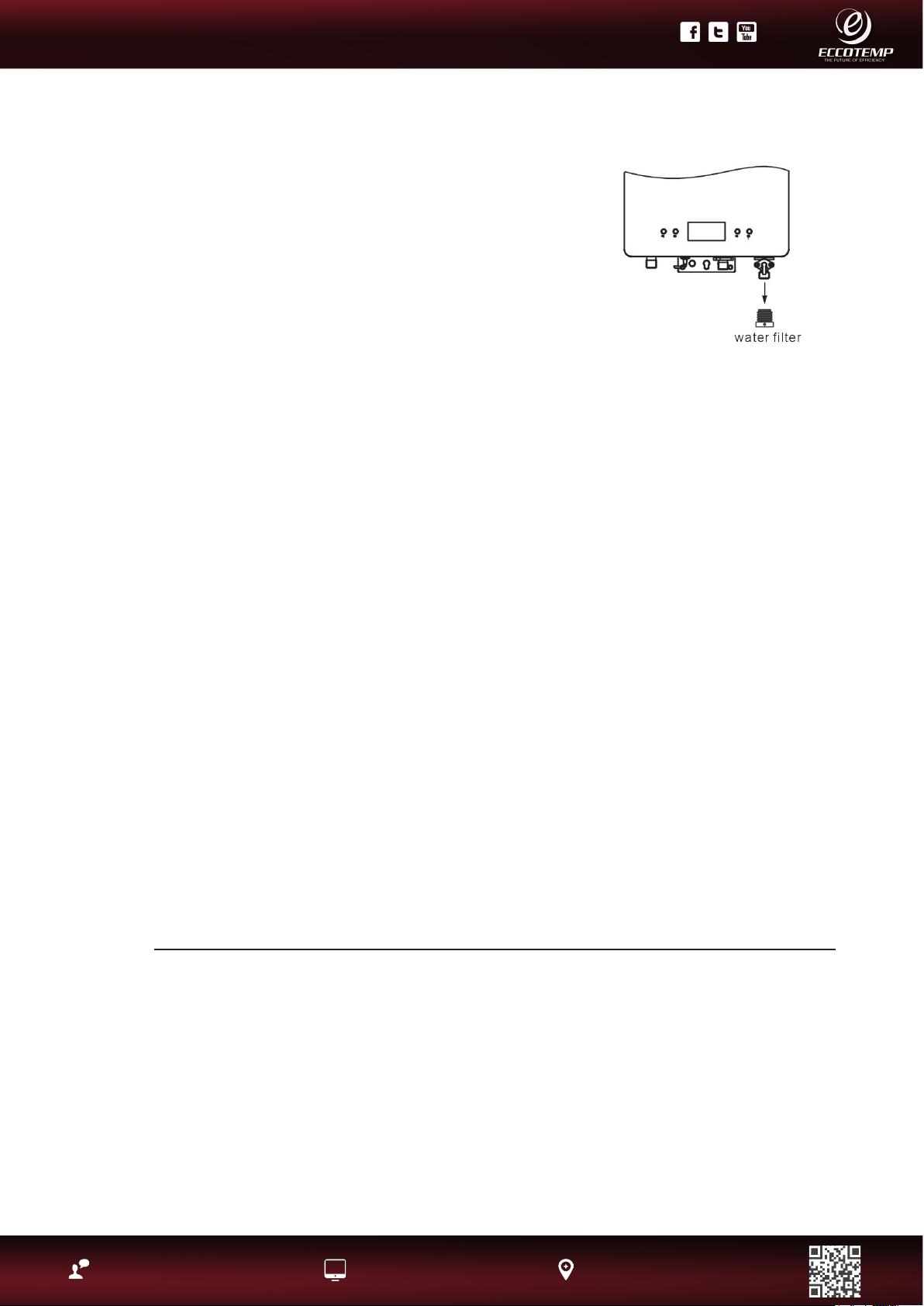
27
Product Support: Eccotemp.com/help-desk Shop Online: Eccotemp.com/products Store Locater: Eccotemp.com/locater
Phone: 866-356-1992 | Email: [email protected] | Address: 315 - A Industrial RD Summerville, SC 29483
PLEASE NOTE: THIS MANUAL IS SUBJECT TO CHANGE AT ANYTIME, TO ENSURE THIS MANUAL IS UP TO DATE PLEASE VISIT OUR HELPDESK AT WWW.ECCOTEMP.COM
FOR ALL OF OUR PRODUCT MANUALS.
PLEASE NOTE: THIS MODEL IS FOR INDOOR PERMANENT INSTALLATIONS ONLY.
CLEANING THE WATER HEATER AND REMOTE CONTROL(S):
• Make sure the unit is OFF and the electrical power supply has been disconnected.
• DO NOT scrub the appliance with a brush.
• Use only mild soapy water, other cleaners may damage the surface of the water heater.
• DO NOT remove any label including the rating plate while cleaning or servicing.
• DO NOT splash water on the remote controls when cleaning.
NOTICE: DO NOT block or obstruct the air intake opening located at the lower left corner of the water heater. A
minimum of 12” is required between this combustion air inlet opening and any obstruction.
Venting System Inspection
The venting system should be inspected annually to ensure all of the vent sections are secure and airtight.
It is recommended that qualied service personnel familiar with Category III venting inspect the venting system.
Check vent connection joint sections with a solution of soapy water to assure airtightness while the unit is
operating. Bubbles around a joint connection indicates a seal leak. Refer to page 14 for vent sealing instructions.
DO NOT operate the unit if vent system shows signs of leaking exhaust.
Check to make sure that the Air Intake and the vent terminal have not been blocked or contain debris.
Vacation and Extended Shut-Down
If the water heater is to remain idle for an extended period of time, the power and water to the appliance should
be turned off.
The water heater and piping should be drained if they might be subjected to freezing temperatures.
After a long shut-down period, the water heater’s operation and controls should be checked by qualied service
personnel.
HOW TO CLEAN THE WATER FILTER:
1. Make sure the unit is OFF and the electrical power supply has
been disconnected.
2. Turn the water supply OFF to the heater.
3. Unscrew the water lter, and slide the lter out.
4. DO NOT tap the lter as it may deform and/or damage the lter.
5. To remove severe dust, use a soft brush and wash with running
water.
6. Return the lter to the water heater and screw in the lter.
7. Turn the electrical power supply and cold water supply ON to the
water heater
Housekeeping continued...
Not Equipped with Anti-Freezing Protection
Draining Procedure
When the temperature falls below 32°F, water in your plumbing system or water heater can turn to ice and then
expand causing damage to the water heater. This damage is not covered under your manufacturer’s warranty. If
these conditions are anticipated, please drain the water heater as follows to help but not guarantee from freezing:
1. Shut off the main gas valve and power
2. Shut off the inlet water valve
3. Open all faucets
4. Take off the drain valve, and allow water to drain for 3 minutes or until the unit is empty.
5. Making sure all water is out, replace the drain valve, and shut off the faucets.
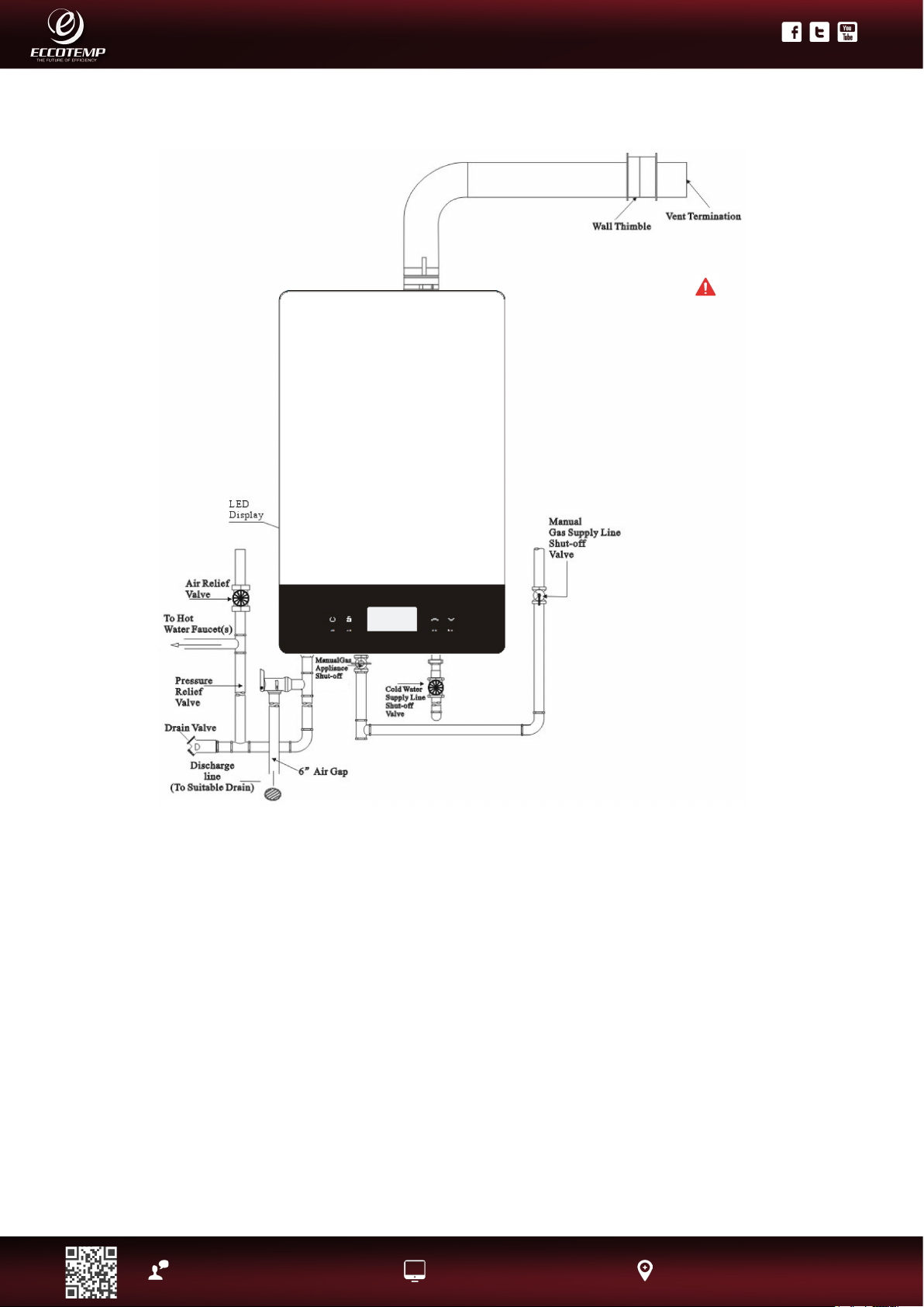
28
Product Support: Eccotemp.com/help-desk Shop Online: Eccotemp.com/products Store Locater: Eccotemp.com/locater
Phone: 866-356-1992 | Email: [email protected] | Address: 315 - A Industrial RD Summerville, SC 29483
PLEASE NOTE: THIS MANUAL IS SUBJECT TO CHANGE AT ANYTIME, TO ENSURE THIS MANUAL IS UP TO DATE PLEASE VISIT OUR HELPDESK AT WWW.ECCOTEMP.COM
FOR ALL OF OUR PRODUCT MANUALS.
PLEASE NOTE: THIS MODEL IS FOR INDOOR PERMANENT INSTALLATIONS ONLY.
Care and cleaning of the water heater.
Draining the Water Heater
Below are instructions for draining water out of the water heater.
1. Turn off the switch on the remote control.
2. Close the gas shut-off valve(s).
3. Close the water shut-off valve.
4. Turn the on/ off switch to the OFF position and disconnect breaker at least 10 seconds after step #1.
5. Open drain valve.
6. Open all hot water faucets. Before proceeding to the next step, make sure that COLD water is coming out of all
hot water faucets.
7. To put the water heater back into operation after draining, follow the steps below.
8. Reinstall the water lter. Close the hot water outlet drain valve.
9. Open the water shut-off valve and close again after making sure that water comes out from hot water faucets.
(This step is to remove air from the water lines.)
10. Reconnect the breaker and turn the on/off switch to the ON position, fully open the gas shut-off valve and the
water shut-off valve.
NOTICE: The water heater may not operate unless the above procedure is followed correctly.
WARNING:
Failure to follow these
instructions while
draining the water
heater can cause
serious damage to the
water heater as well
as personal injury
including scalding.
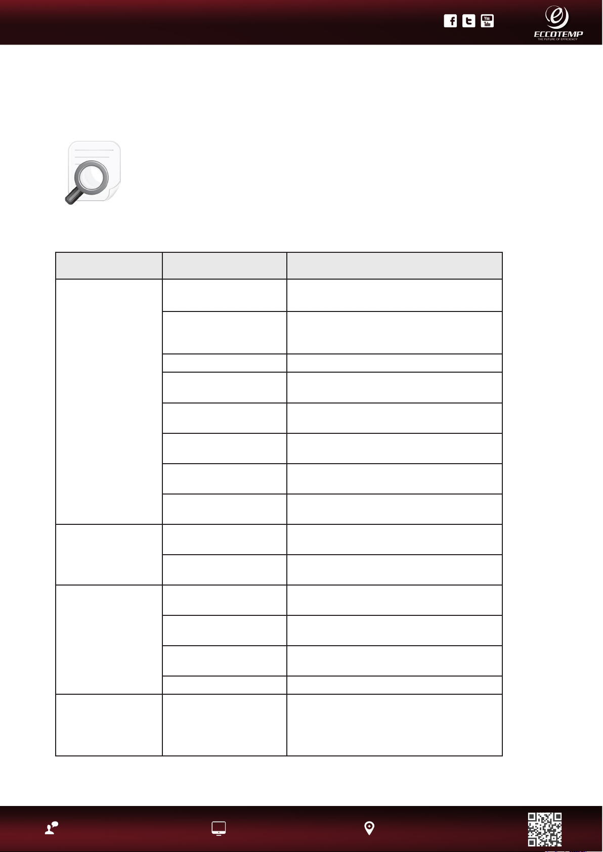
29
Product Support: Eccotemp.com/help-desk Shop Online: Eccotemp.com/products Store Locater: Eccotemp.com/locater
Phone: 866-356-1992 | Email: [email protected] | Address: 315 - A Industrial RD Summerville, SC 29483
PLEASE NOTE: THIS MANUAL IS SUBJECT TO CHANGE AT ANYTIME, TO ENSURE THIS MANUAL IS UP TO DATE PLEASE VISIT OUR HELPDESK AT WWW.ECCOTEMP.COM
FOR ALL OF OUR PRODUCT MANUALS.
PLEASE NOTE: THIS MODEL IS FOR INDOOR PERMANENT INSTALLATIONS ONLY.
Before You Call For Service
Troubleshooting Tips
Save time and money! Review the charts on the following pages rst and you
may not need to call for service.
This water heater incorporates a variety of shut off devices that prevents the
operation of the water heater down if undesirable combustion conditions occur.
Such as the presence of a blockage of the combustion air vent insufcient gas
or pressure which can impact the safe operation of the water heater. Please
contact a Qualied Service Technician if this occurs.
Problem
Possible Cause
What To Do
Not enough or no
hot water
Water shutoff valve is not
fully opened.
Check shutoff valve and open fully.
Hot water faucet is not
fully opened
Open hot water faucet completely.
(The main burner goes off when incoming
water volume is inadequate.
Water piping is frozen Allow piping to thaw.
No electricity or water
supply is cut off.
Check that proper power is being supplied
and/or water supply is adequate.
Unit is not “ON”.
Turn the unit “ON” by the button on the
remote control.
The temperature may be
set too low
Increase the temperature setting.
Mixing Valve malfunction
(if applicable).
Check and replace if necessary.
Error code displayed on
remote control panel
See instructions for Error Code and if
required, contact a dealer for service.
Water not hot
enough
The temperature may be
set too low.
Increase the temperature setting.
The gas valve is not fully
opened.
Check and open the gas valve fully.
Water too hot
The temperature is set
too high
Decrease the temperature setting.
Water shutoff valve is not
fully opened.
Check shutoff valve and open fully.
Small amount of water
has been heated.
Allow more water to ow.
Water lter is clogged Clean the lter with a tooth brush.
Fan continues to
rotate after hot
water faucet is
closed.
This function is to purge
unburned gas 10-15
seconds.
Normal operation. There is no need to call for
service. Check for error code.
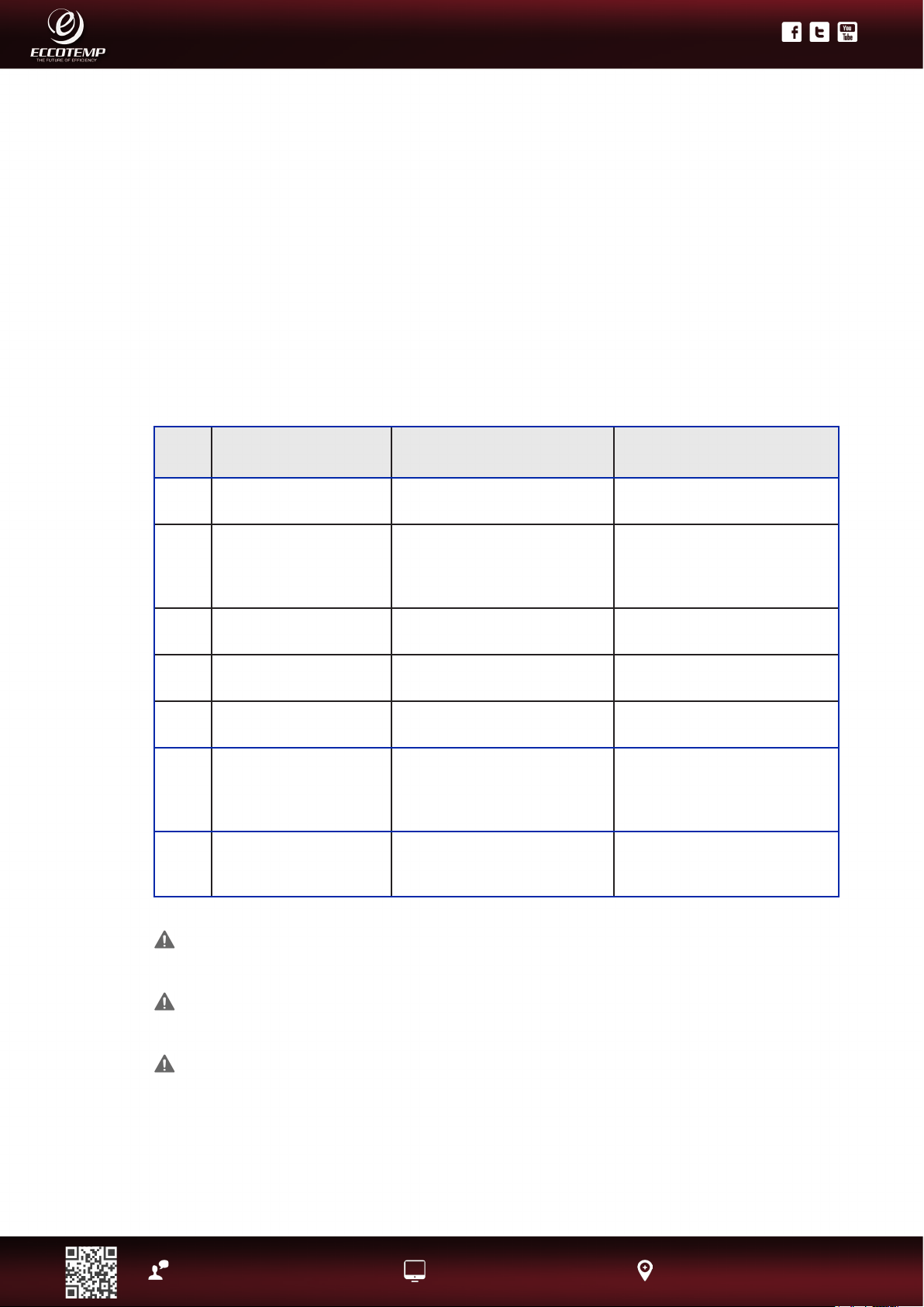
30
Product Support: Eccotemp.com/help-desk Shop Online: Eccotemp.com/products Store Locater: Eccotemp.com/locater
Phone: 866-356-1992 | Email: [email protected] | Address: 315 - A Industrial RD Summerville, SC 29483
PLEASE NOTE: THIS MANUAL IS SUBJECT TO CHANGE AT ANYTIME, TO ENSURE THIS MANUAL IS UP TO DATE PLEASE VISIT OUR HELPDESK AT WWW.ECCOTEMP.COM
FOR ALL OF OUR PRODUCT MANUALS.
PLEASE NOTE: THIS MODEL IS FOR INDOOR PERMANENT INSTALLATIONS ONLY.
Error
Code
Error Description Possible Cause What To Do
E0
Hot water sensor
failure
Junction port loose,
Short circuit
Call for Service
E1
Ignition system failure
The gas valve is not opened or
fully opened, Water shut-off
valve is not open, Junction
port loose
Check and open gas fully,
Check and open water valve,
Call for Service
E2
There is ame when no
water coming in
Electric circuit problem Call for Service
E3
Over-heating protection
Dry Combustion, Problem of
over heating controller
Call for Service
E5
Pressure Switch
Motor problem, Voltage of
power supply is too low
Call for Service
E6
Over-heating
Gas pressure is too high,
Water shutoff valve is
not fully opened, The
temperature is set too low
Check shut-off valve and open
fully, Increase temperature
setting
E7
Solenoid valve
Open circuit of the valve,
short circuit of the valve, none
of the above
Connect the valve, replace the
valve, replace the computer
board
If the error code remains shown:
• Close the hot water faucet and turn off the
switch on the remote control.
• Take the proper action shown below and
attempt operation of the appliance again.
• If the error code is still shown:
• Turn off the hot water faucet and turn off
the switch on the remote control.
• Take note of the error code displayed and
call the customer service assistance number
in the “If You Need Service”
When an error code is displayed:
• Close the hot water faucet, turn off the
switch on the remote control.
• Wait for about 5 minutes before turning the
switch on again.
• Open the hot water faucet.
NOTICE: If an error code other than those listed
below is displayed, immediately turn off the hot
water faucet, take note of the error code, turn
off the switch on the remote control and call the
customer assistance number.
Error Code Guide
CAUTION: For your safety DO NOT attempt repair of gas piping, remote control, burners,
vent connectors or other safety devices. Refer repairs to qualied service personnel.
CAUTION: Make certain power to water heater is “OFF” before removing protective cover
FOR ANY REASON.
CAUTION: Label all wires prior to disconnection when servicing controls. Wiring
errors can cause improper and dangerous operation. VERIFY PROPER OPERATION AFTER
SERVICING.
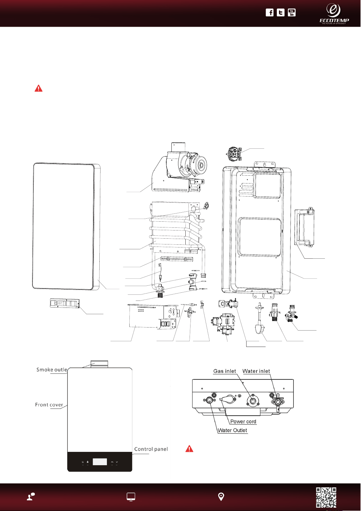
31
Product Support: Eccotemp.com/help-desk Shop Online: Eccotemp.com/products Store Locater: Eccotemp.com/locater
Phone: 866-356-1992 | Email: [email protected] | Address: 315 - A Industrial RD Summerville, SC 29483
PLEASE NOTE: THIS MANUAL IS SUBJECT TO CHANGE AT ANYTIME, TO ENSURE THIS MANUAL IS UP TO DATE PLEASE VISIT OUR HELPDESK AT WWW.ECCOTEMP.COM
FOR ALL OF OUR PRODUCT MANUALS.
PLEASE NOTE: THIS MODEL IS FOR INDOOR PERMANENT INSTALLATIONS ONLY.
Display screen
Front cover
Motor fan
Temperature
controller
Heat exchanger
Fixing board
Seal ring
Water flow sensor
Burner assemblu
Ignition pin
Proportion Valve
Flame sensor
Flame
sensor board
Solenoid valve
Gas inlet pipe
Back cover
Power cord
Gas flute
Water inlet pipe
Computer board
Wind switch
Clip
Hot water
temp. sensor
Replacement Parts
For models using natural or LP gas.
Instructions for placing a parts order
Address parts orders to the distributor or store from where the water heater was
purchased.
All parts orders should include:
• The model and serial number of the water heater from the rating plate.
• Specify type of gas (natural or LP) as marked on the rating plate.
• Part description (as noted below) and number of parts desired.
WARNING: For
your safety,
DO NOT attempt to
disassemble this
unit for any reason
CAUTION: For your safety, DO NOT attempt
repair of electrical wiring, gas piping, burners,
or other safety devices. Refer repairs to
qualied service personnel.
32
Product Support: Eccotemp.com/help-desk Shop Online: Eccotemp.com/products Store Locater: Eccotemp.com/locater
Phone: 866-356-1992 | Email: [email protected] | Address: 315 - A Industrial RD Summerville, SC 29483
PLEASE NOTE: THIS MANUAL IS SUBJECT TO CHANGE AT ANYTIME, TO ENSURE THIS MANUAL IS UP TO DATE PLEASE VISIT OUR HELPDESK AT WWW.ECCOTEMP.COM
FOR ALL OF OUR PRODUCT MANUALS.
PLEASE NOTE: THIS MODEL IS FOR INDOOR PERMANENT INSTALLATIONS ONLY.
Eccotemp Systems ,LLC
Limited Warranty Information
i12 LP & NG
Eccotemp hereby warrants this product to be free of material defects in materials and workmanship when
installed and operated according to Eccotemp’s installation and operating instructions. This Limited Warranty
extends to the original purchaser and subsequent owners, but only while the product remains as the site of
the original installation. This Limited Warranty terminates if moved or reinstalled at a new location. There
are no warranties, express or implied made or given other than contained in this Limited Warranty. No
agent, employee or representative of Eccotemp has any authority to bind Eccotemp to any representation
or warranty concerning the Product not contained in this Limited Warranty. Eccotemp reserves the right and
authority to change, modify or alter this warranty at any given time.
Except as expressly set forth herein, THERE ARE NO REPRESENTATIONS OR WARRANTIES, EXPRESS OR
IMPLIED, INCLUDING, WITHOUT LIMITATION, AS TO MERCHANTABILITY OR FITNESS FOR A PARTICULAR
PURPOSE WITH RESPECT TO ANY GOODS SOLD HEREUNDER. BUYER’S EXCLUSIVE REMEDY IS LIMITED TO
REPAIR OR REPLACEMENT OF THE GOODS SOLD, AT ECCOTEMP’S DISCRETION. ECCOTEMP SHALL NOT BE
LIABLE FOR INCIDENTAL OR CONSEQUENTIAL DAMAGES.
Limited Warranty Period
This Warranty is extended by Eccotemp Systems to the Owner. This warranty takes effect on the date of
installation of the Product or 30 days after the date of purchase, whichever occurs rst, and is effective until
the specied anniversary of such date as follows:
Item Period of Coverage
Heat Exchanger 2 years
All other parts 2 years
Coverage’s are void if the unit is used in a hot water circulation loop, in series with a circulation system or
where an on-demand recirculation system is not incorporated.
Owner is responsible for all other costs incidental to repair such as labor, shipping, delivery and permits.
Proof of purchase required. Products repaired will be covered under this Limited Warranty for the remainder
of term of the original purchase.
Exclusions
Please refer to the Installation Manual and Use & Care Manual supplied with your new Eccotemp Systems product.
This Limited Warranty becomes null and void if any of the following are determined to be a contributing factor by
Eccotemp to the failure of the product:
1. Abuse, misuse, alteration, neglect or misapplication.
2. Improper, dangerous, destructive maintenance procedures or inadequate maintenance.
3. Damages caused by services performed by servicers other than Eccotemp Systems.
4. Installation in a corrosive or otherwise destructive environment.
5. Damage as a result of freezing within the unit or surrounding piping.
6. Scale buildup.
7. Incorrect gas or water pressure.
8. Acts of force Majeure.
9. Damage as a result of use with non-portable, untreated or poorly treated well water, or water with high
PH levels or hardness levels in excess of 12 grains per gallon (200mg/L).
10. Incorrect sizing for the application.
11. Products with original serial numbers that have been removed or altered and cannot be readily determined.
12. Acts of God including, but not limited to; re, ood, or nature disaster.

33
Product Support: Eccotemp.com/help-desk Shop Online: Eccotemp.com/products Store Locater: Eccotemp.com/locater
Phone: 866-356-1992 | Email: [email protected] | Address: 315 - A Industrial RD Summerville, SC 29483
PLEASE NOTE: THIS MANUAL IS SUBJECT TO CHANGE AT ANYTIME, TO ENSURE THIS MANUAL IS UP TO DATE PLEASE VISIT OUR HELPDESK AT WWW.ECCOTEMP.COM
FOR ALL OF OUR PRODUCT MANUALS.
PLEASE NOTE: THIS MODEL IS FOR INDOOR PERMANENT INSTALLATIONS ONLY.
This Product is not to be used as a pool or spa heater.
In the event of an Eccotemp Systems recognized defect, malfunction, or failure to conform to this Warranty and
based upon Eccotemp approval of warranty claim, Eccotemp Systems, at its sole and absolute discretion, will
settle the warrant claim of such defect, malfunction, or failure to conform to this Warranty. In order to make
a claim under this Warranty, The Owner must notify Eccotemp of the failure of the Product to conform to this
Warranty.
Under this Warranty, Eccotemp Systems will only provide replacement parts as described in the “Limited Warranty
Period”. The Owner will be responsible for any cost incurred including labor costs for servicing the unit, shipping,
delivery, and handling of the replacement part, cost for permits or materials necessary for the repair, or incidental
costs resulting from damage external to the unit resulting from the failure.
NOTWITHSTANDING ANYTHING IN THIS WARRANTY TO THE CONTRARY, EXCEPT FOR ECCOTEMP SYSTEMS’
AFFIRMATIVE OBLIGATIONS EXPRESSLY SET FORTH IN THIS WARRANTY, ECCOTEMP SYSTEMS DISCLAIMS ANY
AND ALL WARRANTIES, EITHER EXRESS OR IMPLIED, REGARDING THE PRODUCT AND ITS FUNCTIONALITY,
PERFORMANCE, MERCHANTABILITY, FITNESS FOR PARTICULAR PURPOSE OR INTELLECTUAL PROPERTY RIGHTS.
ECCOTEMP SYSTEMS DISCLAIMS ALL OTHER OBLIGATIONS OR LIABILITIES ON ITS PART AND NEITHER ASSUMES
NOR AUTHORIZES ANY OTHER PERSON TO ASSUME FOR ECCOTEMP SYSTEMS AN OTHER LIABILITIES IN
CONNECTION WITH THE PERFORMANCE OF THE PRODUCT. THIS WARRANTY ONLY COVERS REPLACEMENT PARTS
AND DOES NOT COVER COST OF LABOR OR SERVICES UNDER ANY CIRCUMSTANCES.
Systems by any other part for damages of any kind, including, but not limited to incidental and consequential
damages, arising out of the subject matter of this Agreement. Some States do not allow exclusion or limitation
of incidental or consequential damages, so the above limitation or exclusion may not apply to you. This warranty
gives you specic legal rights. You may also have other rights that vary from State to State.