Loading ...
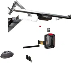
STEP 6 – Hang the C-rail
NOTE: The control head is always mounted on the side the door retracts to. For example: If you are standing inside
the building looking out and the door opens to the right, the control head goes on the right side, too. Likewise, if the
door opens to the left, the control head is mounted to on the left side.
a. Attach the rail end bracket to the end bracket bracket so that the center of the rail is in line with the door arm. Be
sure push the screws up through the bottom of the holes.
b. Close the doors so that the door arm is near the center bracket. The door arm can provide a resting place for the
rail, but be careful that the rail doesn’t slide off.
c. Walk the opener rail up the ladder to the header.
d. Slide the C-rail into the center header bracket and secure with the pin. Attach locking c-clips to secure.
e. Attach rail to remaining header mounting brackets using the ceiling brackets
Note: The rail and control box will extend beyond the jamb header bracket by about 4 feet, depending on the
size of your opening.
STEP 7 – Connect the motor carriage to the door arm
a. Attach the j-bar to the motor carriage. Guide the bolt, (long) through the holes in the motor carriage and the door
arm. Secure with the locking c-clip.
b. Connect the j-bar to the door arm using the angle bracket attached to the door arm.
STEP 8 – Wall Station & Photocells
Mount the wall station. The most common mounting location is the inside face of the jamb. The distance to the floor
must be at least 5’ so that children cannot reach the wall station. The wall station is programmed just like the 4-button
remote control (see below).
Select the mounting location:
• outside of the range of motion of the door and opener mechanics
• so the user can see the door directly
• when operating the wall station, the user can remain outside of the range of motion of the door and opener
mechanics on a flat surface
Install the Photo Eyes
a. Look for a suitable installation position for the mounting bracket inside the building to the left and the right of the
door. Typically, the photo eyes are mounted to the door jambs, about 18” off of the floor.
b. Hold the mounting bracket to the wall and mark the mounting points. The height and angle of the bracket can be
adjusted through the slotted holes.
c. Drill holes for the plywood screws.
d. Screw in two plywood screws 6 x 40 mm.
e. Pre-attach the carriage bolt M6 and the wing nut M6 to the mounting bracket.
f. Slide the transmitter over the head of the carriage bolt M6 and tighten the wing nut M6. The position of the photo
eyes can be adjusted through the slotted holes.
g. Mount the receiver on the opposite side in the same way.
h. Run the two sets of wires from the photo eyes to the control housing.
i. Use staples to keep wires in place.
Connect photo eyes to the control housing.
a. Remove the red cover of the control housing
b. Strip off insulation approx. 3/8” from the wire ends (transmitter and receiver).
28 en
6. Slide the transmitter (4) over the head of the carriage
bolt M6 (1) and tighten the wing nut M6 (2). The position
of the photo eyes can be adjusted through the slotted
holes (5).
7. Mount the receiver on the opposite side in the same way.
8. Run the two sets of wires (6) from the photo eyes to the
control housing.
9. Use staples to keep wires in place.
10.5. Connection
Connect photo eyes to the control housing
1. Remove the red cover (1) of the control housing (2).
2. Strip off insulation approx. 3/8“ (10 mm) from the wire
ends (transmitter and receiver).
2
1
14
15
16
R
13
3
4
5
6
1
3
2
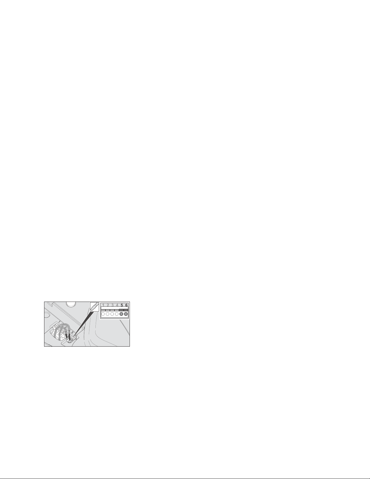
3. Guide both sets of wires (1) from the outside through the
opening (2) into the control housing (3).
4. Connect one wire of the transmitter to terminal 5 and the
other wire to terminal 6.
5. Connect one wire of the receiver to terminal 5 and the
other wire to terminal 6.
Note
If you have inadvertently inserted a wire end incorrectly,
you can open the terminal using a small slotted screwdriver
(press down) and pull out the wire end.
10. Photo Eyes
c. Guide both sets of wires from the photocells through the opening into the control housing.
d. Connect one wire of the transmitter to terminal 5 and the other wire to terminal 6.
e. Connect one wire of the receiver to terminal 5 and the other wire to terminal 6.
Adjusting the photo eyes
If the LED in the photo eye transmitter lights up continuously green and the LED in the receiver lights up red, the
photo eyes are set correctly. Only the functioning must now be subsequently checked, please see “Testing the photo
eyes function.” If both LEDs do not light up continuously, the photo eyes have to be adjusted as follows: Loosen the
wing nut either on the transmitter or the receiver and adjust the position until both LEDs light up continuously. By
loosening the screw, the adjustment angle can also be changed.
STEP 9 – Install the Control Head
a. Make sure the contact on the slide in part faces down.
b. Slide the control housing all the way onto the rail.
c. Slide in the fastening plastic bolt all the way through the hole of the control housing.
d. Turn the fastening bolt a half turn in the clockwise direction up to the stop position using a medium slotted-
screwdriver (see graphic). If a half turn is not possible, the control housing is not correctly attached to the C-rail.
Move the control housing slightly while sliding in the fastening bolts up to the stop position.
2
Loading ...
Loading ...