Loading ...
By default, this thermostat has 4 separate program periods for both Heat and Cool modes, they are:
MORN, DAY, EVE, and NITE. Each period ends at the start time of the next upcoming period. The Heat
temperature programs are set while the mode switch is in the HEAT position, and the Cool temperature
programs are set while the mode switch is in the COOL.
NOTE: If the thermostat is configured to use only 2 periods per day (instead of the factory default of 4
periods per day), the thermostat will only use the DAY and NITE period designations. The MORN and
EVE periods will not be used or visible on the screen.
TO SET A TEMPERATURE PROGRAM: Choose either HEAT or COOL mode. Move the Set Slide switch to
the TEMP PROG position. Programming will start with Monday. Use the UP/DOWN buttons to adjust the
start time for the MORN period, and then press the NEXT button to advance. Use the UP/DOWN buttons
to adjust the set temperature for the MORN period, and then press the NEXT button to advance. Now
adjust the start time and set temperature for the DAY period, pressing the NEXT button after each item
to advance. Continue with these same steps to adjust the start times and set temperatures for the EVE
and NITE program periods.
When the last period is finished for each day (or group of days), the thermostat will advance forward
into the next day (or group of days).
NOTE: If a temperature program routine is not desired, you may change ITEM #02 in the Setup Options
to “3” for manual non-programmable.
Return the Set Slide switch back to the RUN position when you are finished.
Emergency Heat mode is only present if the thermostat is setup for a Heat Pump configuration (SETUP
MENU ITEM #06 set to “HP”). With the System Mode switch in the HEAT position and the Set Slide
switch in the RUN position, one single press of the EMER button will activate Emergency Heat mode. A
single press again will deactivate Emergency Heat mode, and return back to regular Heat mode. While
in Emergency Heat mode, the word “EMER” will be present in the middle portion of the display screen.
If a mains power loss occurs while in Emergency Heat mode, the thermostat will continue to remain in
Emergency Heat mode even after the mains power comes back on.
Emergency Heat mode will prevent the first stage (outdoor unit) of your heat pump system from turning
on, and uses only the “W2” wire terminal (Auxiliary Heat) as the primary heating source. This not only
prevents the heat pump from wasting energy when outdoor temperatures are too low to provide efficient
operation, but it can also prevent permanent mechanical damage to the heat pump unit itself if outside
temperatures are below the manufacturer’s recommendations for running the outdoor unit. As every
heat pump has different operating characteristics, you should always refer to your particular heat
pump’s literature to determine when the manufacturer recommends changing over to Emergency Heat
mode. In general for most heat pump systems, use Emergency Heat mode whenever the outside
temperature is less than 32F degrees.
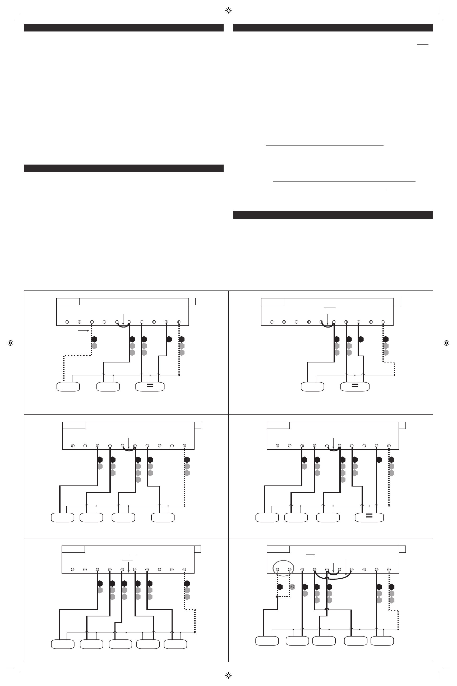
• If the information provided in the following wiring diagrams does not clearly represent or match your
system, please refer to the “TECHNICAL ASSISTANCE” section of this manual, and contact us before
removing any of your existing thermostat wiring.
• All of the dashed wires shown in the wiring diagrams are either optional, or their usage depends
upon your specific system type or brand. For example: Diagram #1 shows the fan wire as optional.
If your system does not have a fan, than this terminal will not be used.
• Terminal letters shown in black represent typical wiring applications. Depending upon the brand of
your specific system or thermostat, your terminal letters may not match exactly. Terminal letters
shown in gray represent other possible wiring designations that you might see on your existing
thermostat terminals.
• The optional “C” terminal is used for powering the thermostat by the 24 volts supplied by your
heating/cooling system, using the System Common wire. This can be used alone, or in addition to
installing batteries as a backup. NOTE: when using batteries, connecting the System Common wire
to the thermostat is not necessary for heating and cooling to function properly.
• If your old thermostat has both a “Y” and “C” wire present, then “C” is most likely a System Common
wire.
• For Heat Pump systems, you will use either the “O” terminal or the “B” terminal on this thermostat,
but not both. If your old thermostat has both an “O” and a “B” wire present
, then “B” is likely a
System Common wire and may be connected to the “C” terminal. Connecting a System Common wire
to this thermostat’s “B” terminal may damage the thermostat, and also your heating and cooling
system.
• Some Heat Pump systems have a wire for AUX electric heat (usually W2), and also a separate wire for
Emergency electric heat (usually E). This thermostat uses the W2 terminal for both AUX heat and
Emergency heat. Tape off your “E” wire, and confirm that all components function without it
.
• If replacing an old thermostat that has a mechanical clock, there may be TWO
wires labeled as “C”
for the clock power. Do not connect either of them to this thermostat. Cover their bare ends with
tape so they cannot touch anything.
If you have any problems installing or using this thermostat, please carefully and thoroughly review the
instruction manual. If you still require assistance, please contact our Technical Assistance department
at 856-234-8803 during regular business hours between 8:00AM and 4:30PM Eastern Time, Monday
through Friday. You can also receive technical assistance online anytime day or night at
http://www.luxproducts.com. Our website offers you troubleshooting guides, answers to the most
common technical questions, and also permits you to email your questions to our technical support staff
at your convenience.
NOTE: THE BLACK TERMINAL LETTERS ARE TYPICAL, GRAY TERMINAL LETTERS ARE BRAND SPECIFIC
W1
4
W
XF
G
B*
W2
RH
V
R
W1 A W2O B CG Y RC RH
1-STAGE OR 2-STAGE, HEATING ONLY
(INCLUDING MILLIVOLT)
(2-WIRE HEAT USE “RH” & “W1”)
Factory RH-RC Jumper Wire Installed
#1
2, 3, 4, 5 WIRES
C
HEATER
STAGE
1
STAGE
2
FAN
SYSTEM 24V
TRANSFORMER
SYSTEM COMMON
FAN WIRE
MAY NOT BE
PRESENT IN
ALL SYSTEMS
O
P
T
I
O
N
A
L
NOTE: THE BLACK TERMINAL LETTERS ARE TYPICAL, GRAY TERMINAL LETTERS ARE BRAND SPECIFIC
X
B*
C
RH
V
R
W1
4
W A
W1 A W2O B CG Y RC RH
HOT WATER HEATING ONLY
(WITH A 3-WIRE ZONE VALVE)
Factory RH-RC Jumper Wire Installed
#2
3, 4 WIRES
SYSTEM 24V
TRANSFORMER
SYSTEM COMMON
OPEN = Heat On
CLOSE = Heat Off
3-WIRE ZONE VALVE
OPEN CLOSE
O
P
T
I
O
N
A
L
NOTE: THE BLACK TERMINAL LETTERS ARE TYPICAL, GRAY TERMINAL LETTERS ARE BRAND SPECIFIC
RH
RC
V
R
Y1
6
Y
F
G
XW1
4
W
B*
W1 A W2 CGO BYRC RH
CONVENTIONAL (NON HEAT PUMP)
1-STAGE HEATING AND 1-STAGE COOLING
Factory RH-RC Jumper Wire Installed
#4
C
FAN
SYSTEM 24V
TRANSFORMER
SYSTEM COMMON
HEATER
AIR
CONDITIONER
4, 5 WIRES
O
P
T
I
O
N
A
L
NOTE: THE BLACK TERMINAL LETTERS ARE TYPICAL, GRAY TERMINAL LETTERS ARE BRAND SPECIFIC
W2
RH
RC
V
R
Y1
6
Y
F
G
XW1
4
W
B*
W1 A W2 CGO BYRC RH
CONVENTIONAL (NON HEAT PUMP)
2-STAGE HEATING AND 1-STAGE COOLING
Factory RH-RC Jumper Wire Installed
#5
C
FAN
SYSTEM 24V
TRANSFORMER
SYSTEM COMMON
AIR
CONDITIONER
5, 6 WIRES
O
P
T
I
O
N
A
L
HEATER
STAGE
1
STAGE
2
NOTE: THE BLACK TERMINAL LETTERS ARE TYPICAL, GRAY TERMINAL LETTERS ARE BRAND SPECIFIC
X
B*
C
R
V
RH
R
V
RC
Y1
6
Y
F
G
W1
4
W
W1 A W2O B CG Y RC RH
CONVENTIONAL (NON HEAT PUMP) 1-STAGE HEATING AND
1-STAGE COOLING WITH TWO SEPARATE 24V TRANSFORMERS
Factory RH-RC Jumper Wire REMOVED
#6
FAN
HEAT 24V
TRANSFORMER
COOL 24V
TRANSFORMER
SYSTEM COMMON
HEATER
AIR
CONDITIONER
5, 6 WIRES
O
P
T
I
O
N
A
L
NOTE: THE BLACK TERMINAL LETTERS ARE TYPICAL, GRAY TERMINAL LETTERS ARE BRAND SPECIFIC
CUSTOMER INSTALLED Y-W1 Jumper Wire
X
B*
C
W3
W
W2
O
F
G
Y1
6
Y
RC
V
R
W1 A W2O B CG Y RC RH
2-HEAT / 1-COOL, HEAT PUMP SYSTEM
WITH AUX AND EMERGENCY HEAT
Factory RH-RC Jumper Wire Installed
#8
FAN
SYSTEM 24V
TRANSFORMER
SYSTEM COMMON
5, 6 WIRES
HEAT PUMP
REVERSING
VALVE
** Use “O” or “B”
Terminals, Never Both
AUX / EMERG.
HEAT
O
P
T
I
O
N
A
L
EMERGENCY HEAT OPERATION:
TECHNICAL ASSISTANCE:
WIRING DIAGRAM NOTES:
53596
TEMPERATURE PROGRAMMING: